
6-2
Conservation of Mass
constant). To be steady, the mass flow rate through the device must remain constant.
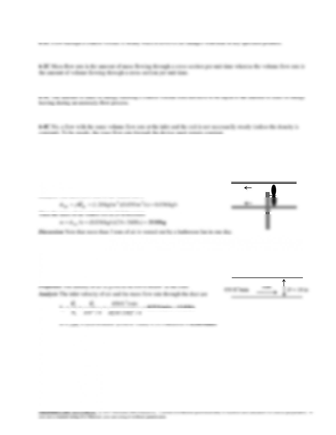
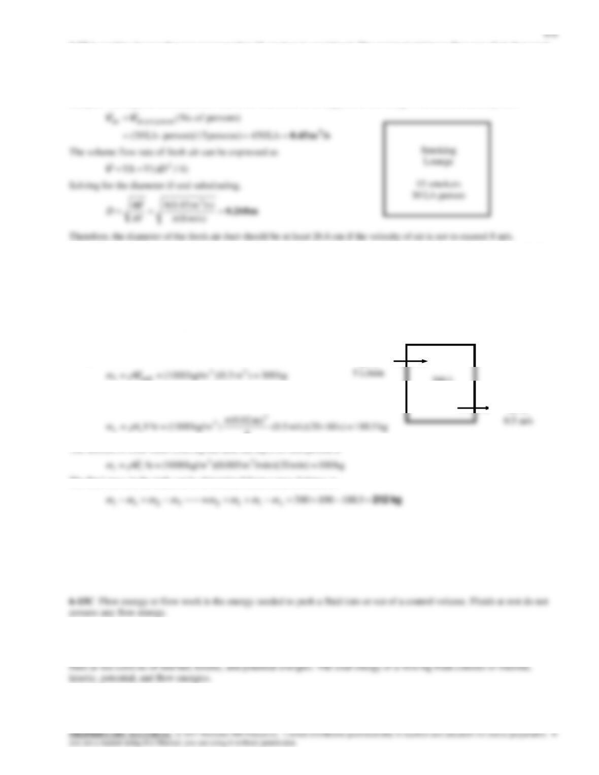
6-5 The ventilating fan of the bathroom of a building runs continuously. The mass of air “vented out” per day is to be
determined.
Assumptions Flow through the fan is steady.
Properties The density of air in the building is given to be 1.20 kg/m3.
Analysis The mass flow rate of air vented out is
6-6E The ducts of an air-conditioning system pass through an open area. The inlet velocity and the mass flow rate of air are
to be determined.
Assumptions Flow through the air conditioning duct is steady.
ft/s 13.8ft/min825
4/ft 10/12
/minft 450
4/ 2
3
2
1
1
1
1
D
A
V
VV
lbm/s0.585 lbm/min 35.1min)/ft 450)(lbm/ft 078.0( 33
11
V
m
6-3
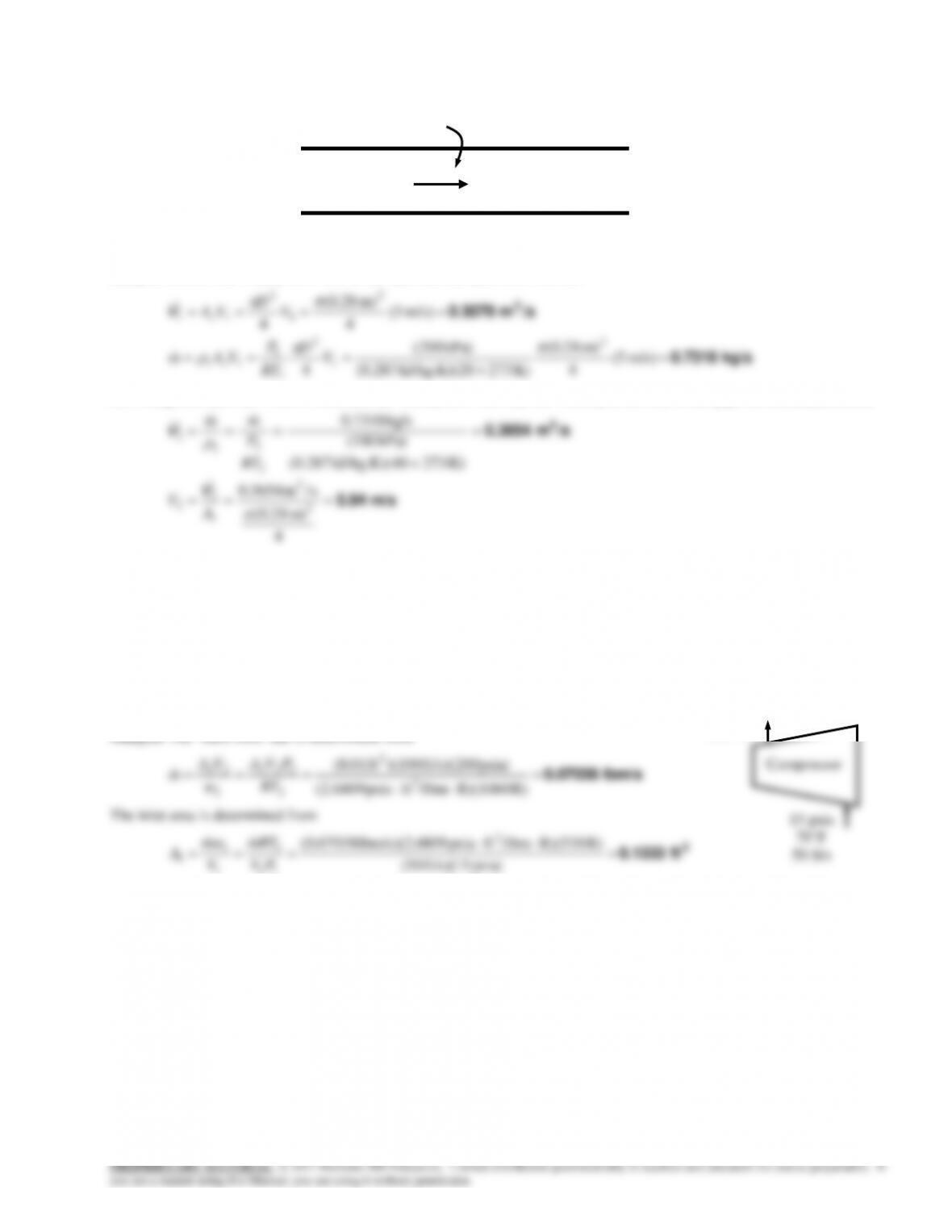
6-7 Air flows through a pipe. Heat is supplied to the air. The volume flow rates of air at the inlet and exit, the velocity at the
exit, and the mass flow rate are to be determined.
Properties The gas constant for air is 0.287 kJ/kg.K (Table A-2).
Analysis (a) (b) The volume flow rate at the inlet and the mass flow rate are
kg/s 0.7318
/sm 0.3079 3
m/s) 5(
4
m) 28.0(
K) 2730kJ/kg.K)(2 287.0(
kPa) (200
4
m/s) 5(
4
m) 28.0(
4
2
1
2
1
1
11
2
1
2
11
V
D
RT
P
VAm
V
D
VA
c
c
V
(c) Noting that mass flow rate is constant, the volume flow rate and the velocity at the exit of the pipe are determined from
m/s 5.94
/sm 0.3654 3
4
m) 28.0(
s/m 3654.0
K) 2730kJ/kg.K)(4 287.0(
kPa) (180
kg/s 7318.0
2
3
2
2
2
2
2
2
c
A
V
RT
P
mm
V
V
6-8E Helium at a specified state is compressed to another specified state. The mass flow rate and the inlet area are to be
determined.
Assumptions Flow through the compressor is steady.
Properties The gas cosntant of helium is R = 2.6809 psiaft3/lbmR (Table A-1E)
Analysis The mass flow rate is determined from
lbm/s 0.07038
R) R)(1060/lbmftpsia (2.6809
psia) ft/s)(200 )(100ft 01.0(
3
2
2
222
2
22
RT
PVAVA
m
v
The inlet area is determined from
2
ft 0.1333
psia) 15(ft/s) 50(
R) R)(530/lbmftpsia 809lbm/s)(2.6 (0.07038 3
11
1
1
1
1PV
RTm
V
m
A
v
Compressor
200 psia
600°F
0.01 ft2
15 psia
70°F
50 ft/s
Air
200 kPa
20C
5 m/s
Q
180 kPa
40C
6-4
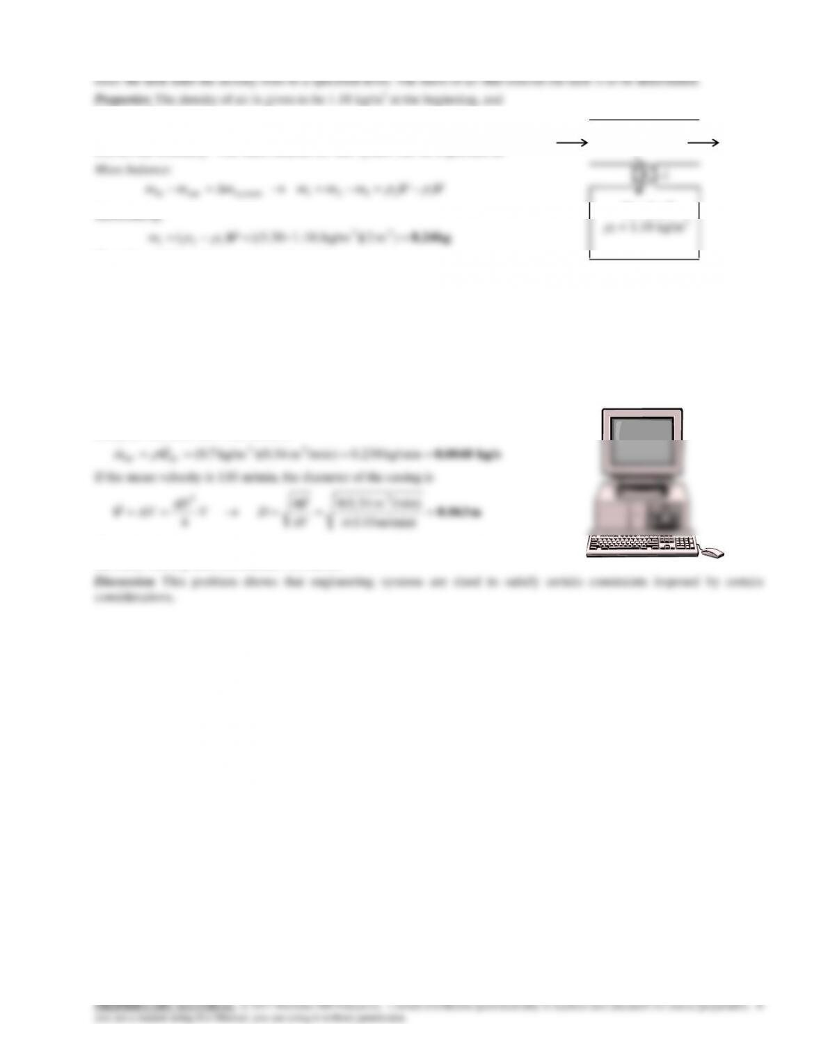
6-9 A rigid tank initially contains air at atmospheric conditions. The tank is connected to a supply line, and air is allowed to
5.30 kg/m3 at the end.
Analysis We take the tank as the system, which is a control volume since mass
crosses the boundary. The mass balance for this system can be expressed as
Substituting,
kg 8.24 )m 2](kg/m 1.18)–(5.30[)( 33
12
V
i
m
Therefore, 8.24 kg of mass entered the tank.
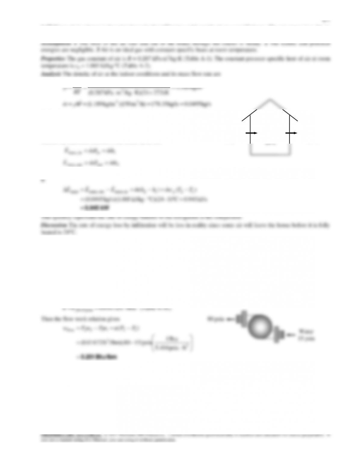
6-10 A desktop computer is to be cooled by a fan at a high elevation where the air density is low. The mass flow rate of air
through the fan and the diameter of the casing for a given velocity are to be determined.
Assumptions Flow through the fan is steady.
Properties The density of air at a high elevation is given to be 0.7 kg/m3.
Analysis The mass flow rate of air is
4
V
Therefore, the diameter of the casing must be at least 6.3 cm to ensure that
the mean velocity does not exceed 110 m/min.
V
1 = 2 m3
1 = 1.18 kg/m3

6-8
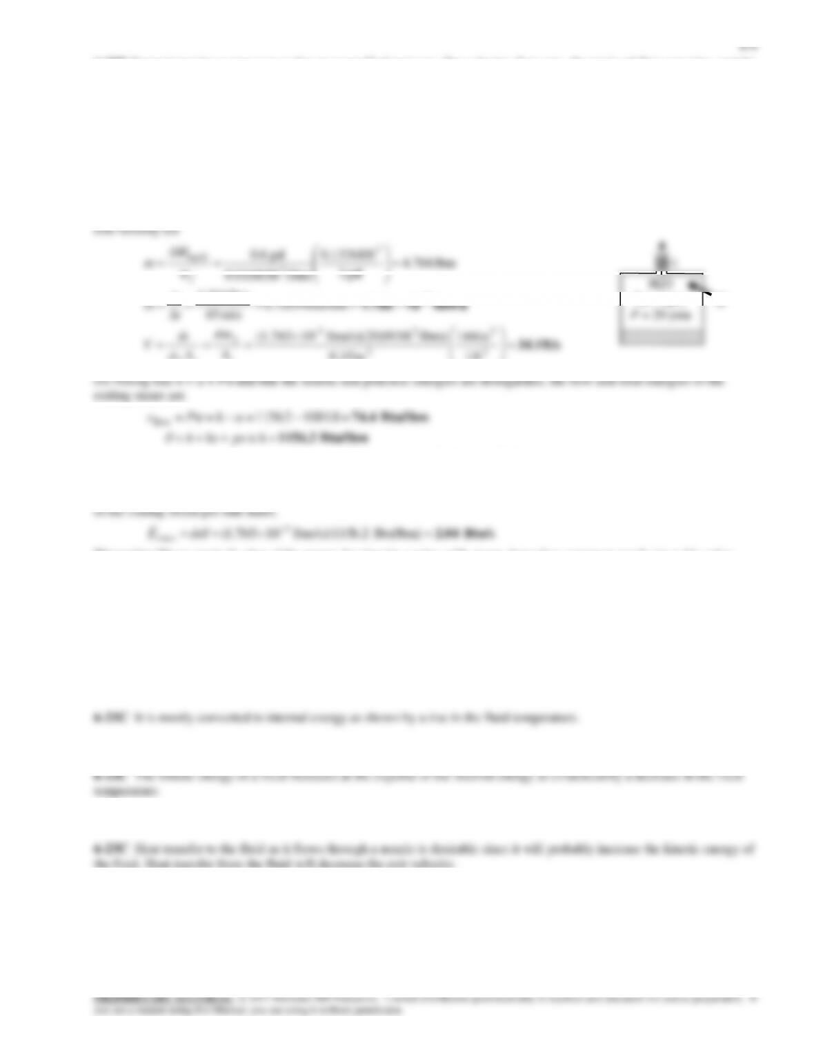
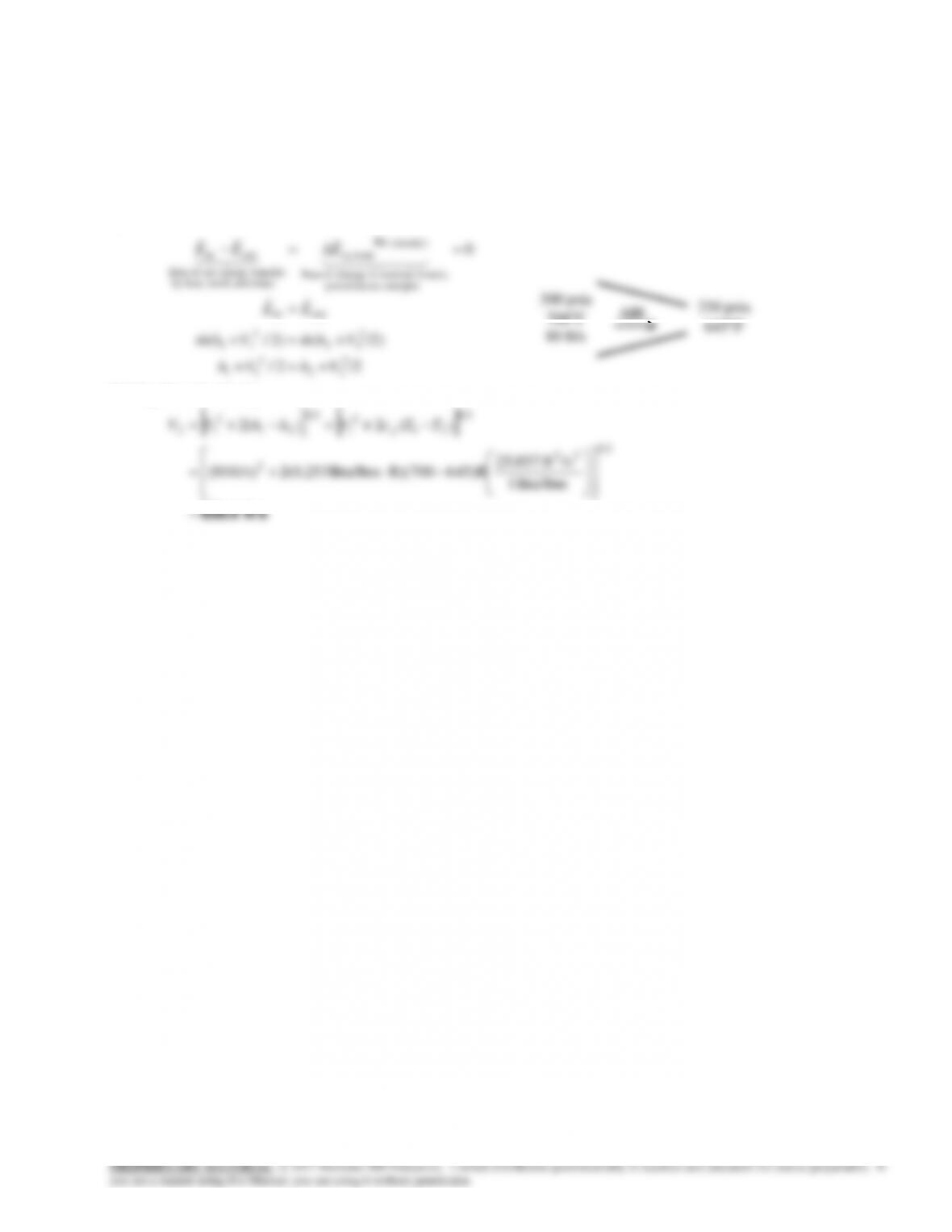
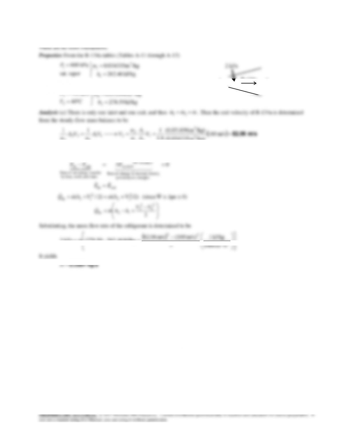
6-19 Refrigerant-134a enters a compressor as a saturated vapor at a specified pressure, and leaves as superheated vapor at a
specified rate. The rates of energy transfer by mass into and out of the compressor are to be determined.
Assumptions 1 The flow of the refrigerant through the compressor is steady. 2 The kinetic and potential energies are
negligible, and thus they are not considered.
Properties The enthalpy of refrigerant-134a at the inlet and the exit are (Tables
A-12 and A-13)
kJ/kg 19.239
MPa 14.0@1 g
hh
kJ/kg 82.296
C60
MPa 8.0
2
2
2
h
T
P
Analysis Noting that the total energy of a flowing fluid is equal to its enthalpy when
the kinetic and potential energies are negligible, and that the rate of energy transfer by
mass is equal to the product of the mass flow rate and the total energy of the fluid per
unit mass, the rates of energy transfer by mass into and out of the compressor are
R-134a
compressor
(2)
0.8 MPa
60C
6-11
6-25E Air is accelerated in an adiabatic nozzle. The velocity at the exit is to be determined.
Assumptions 1 This is a steady-flow process since there is no change with time. 2 Air is an ideal gas with constant specific
heats. 3 Potential energy changes are negligible. 4 There are no work interactions. 5 The nozzle is adiabatic.
Properties The specific heat of air at the average temperature of (700+645)/2=672.5°F is cp = 0.253 Btu/lbmR (Table A-
2Eb).
Analysis There is only one inlet and one exit, and thus
mmm 21
. We take nozzle as the system, which is a control
volume since mass crosses the boundary. The energy balance for this steady-flow system can be expressed in the rate form
as
kinetic, internal,in change of Rate
(steady) 0
sy stem
nsferenergy tranet of Rate
outin 0
EEE
/2+2/
2
22
2
11
VhVh
Solving for exit velocity,
ft/s 838.6
5.0
22
2
5.0
21
2
1
5.0
21
2
12
Btu/lbm 1
/sft 25,037
)(2)(2 TTcVhhVV p
6-12
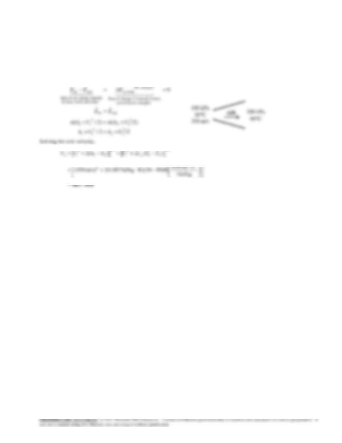
6-26 Air is decelerated in an adiabatic diffuser. The velocity at the exit is to be determined.
Assumptions 1 This is a steady-flow process since there is no change with time. 2 Air is an ideal gas with constant specific
heats. 3 Potential energy changes are negligible. 4 There are no work interactions. 5 The diffuser is adiabatic.
Properties The specific heat of air at the average temperature of (30+90)/2 = 60°C = 333 K is cp = 1.007 kJ/kgK (Table A-
2b).
Analysis There is only one inlet and one exit, and thus
mmm 21
. We take diffuser as the system, which is a control
volume since mass crosses the boundary. The energy balance for this steady-flow system can be expressed in the rate form
as
kinetic, internal,in change of Rate
(steady) 0
sy stem
nsferenergy tranet of Rate
outin 0
EEE
6-13
6-27 Air is accelerated in a nozzle from 120 m/s to 380 m/s. The exit temperature and pressure of air are to be determined.
Assumptions 1 This is a steady-flow process since there is no change with time. 2 Air is an ideal gas with variable specific
heats. 3 Potential energy changes are negligible. 4 The device is adiabatic and thus heat transfer is negligible. 5 There are no
work interactions.
Properties The enthalpy of air at the inlet temperature of 500 K is h1 = 503.02 kJ/kg (Table A-21).
Analysis (a) There is only one inlet and one exit, and thus
m m m
1 2
. We take nozzle as the system, which is a control
volume since mass crosses the boundary. The energy balance for this steady-flow system can be expressed in the rate form
as
outin
energies etc. potential,
kinetic, internal,in change of Rate
(steady) 0
sy stem
mass and work,heat,by
nsferenergy tranet of Rate
outin 0
EE
EEE
2
0
0)peW (since /2)V+()2/(
1
2
12
2
22
2
11
VV
hh
QhmVhm
or,
/sm 1000
kJ/kg 1
2
m/s 120m/s 380
222
22
2
1
2
2
Then from Table A-21 we read T2 = 436.5 K 437 K
(b) The exit pressure is determined from the conservation of mass relation,
1
111 VA
AIR
1
2
6-15
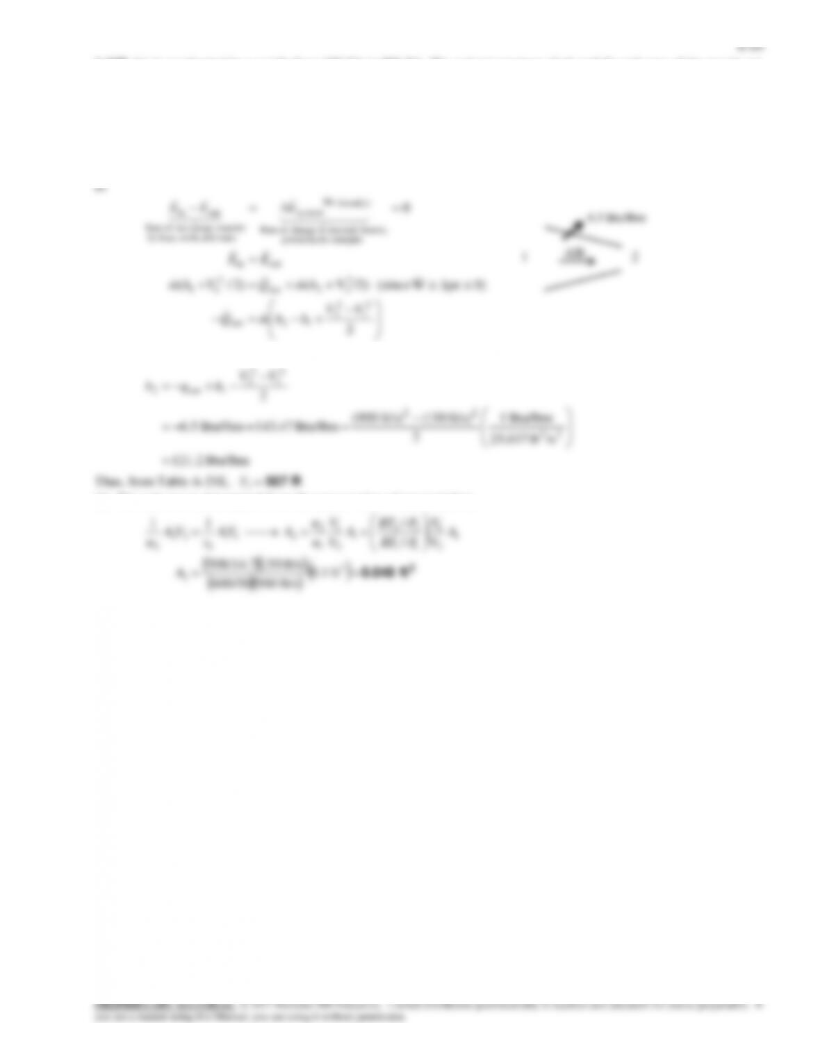
6-29 Steam is accelerated in a nozzle from a velocity of 40 m/s to 300 m/s. The exit temperature and the ratio of the inlet–to–
exit area of the nozzle are to be determined.
Assumptions 1 This is a steady-flow process since there is no change with time. 2 Potential energy changes are negligible. 3
There are no work interactions. 4 The device is adiabatic and thus heat transfer is negligible.
kJ/kg 3231.7
C400
1
1
h
T
Analysis (a) There is only one inlet and one exit, and thus
m m m
1 2
. We take nozzle as the system, which is a control
volume since mass crosses the boundary. The energy balance for this steady-flow system can be expressed in the rate form
as
kinetic, internal,in change of Rate
(steady) 0
sy stem
nsferenergy tranet of Rate
outin 0
EEE
6-17
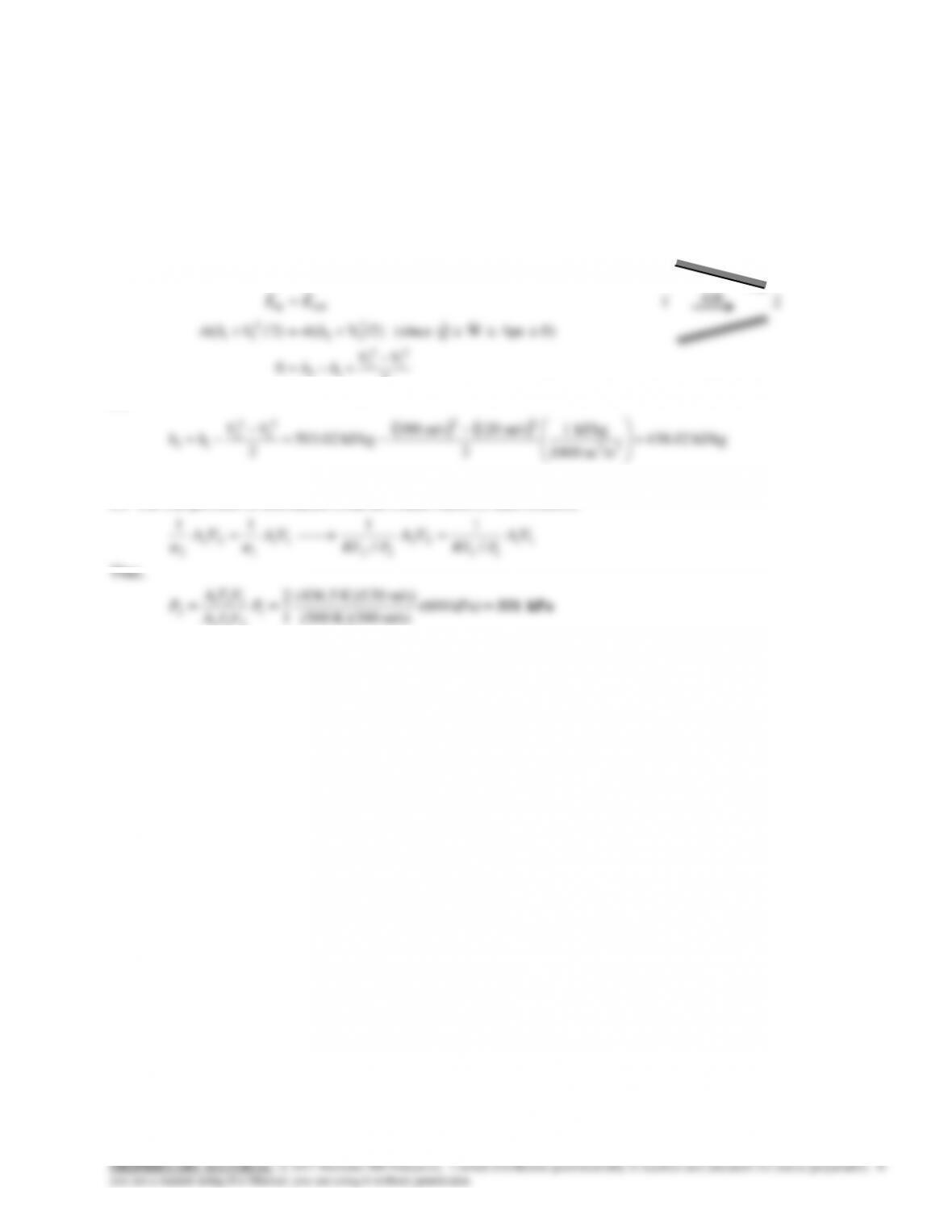
6-31 CO2 gas is accelerated in a nozzle to 450 m/s. The inlet velocity and the exit temperature are to be determined.
Assumptions 1 This is a steady-flow process since there is no change with time. 2 CO2 is an ideal gas with variable specific
heats. 3 Potential energy changes are negligible. 4 The device is adiabatic and thus heat transfer is negligible. 5 There are no
work interactions.
Properties The gas constant and molar mass of CO2 are 0.1889 kPa.m3/kg.K and 44 kg/kmol (Table A-1). The enthalpy of
CO2 at 500C is
h
1
30,797 kJ/kmol (Table A-20).
Analysis (a) There is only one inlet and one exit, and thus
m m m
1 2
. Using the ideal gas relation, the specific volume is
determined to be
kPa 1000
K 773K/kgmkPa 0.1889 3
3
1
1
RT
Thus,
m/s60.8
m1040
/kgm 0.146kg/s 6000/36001
24
3
1
1
111
1
A
m
VVAm
v
v
(b) We take nozzle as the system, which is a control volume since mass crosses the boundary. The energy balance for this
steady-flow system can be expressed in the rate form as
kinetic, internal,in change of Rate
(steady) 0
sy stem
nsferenergy tranet of Rate
outin 0
EEE
2
0
1
2
12
VV
hh
Substituting,
kJ/kg 1
m/s 60.8m/s 450
2
22
2
1
2
2
12
M
VV
hh
CO2
1
2
6-19
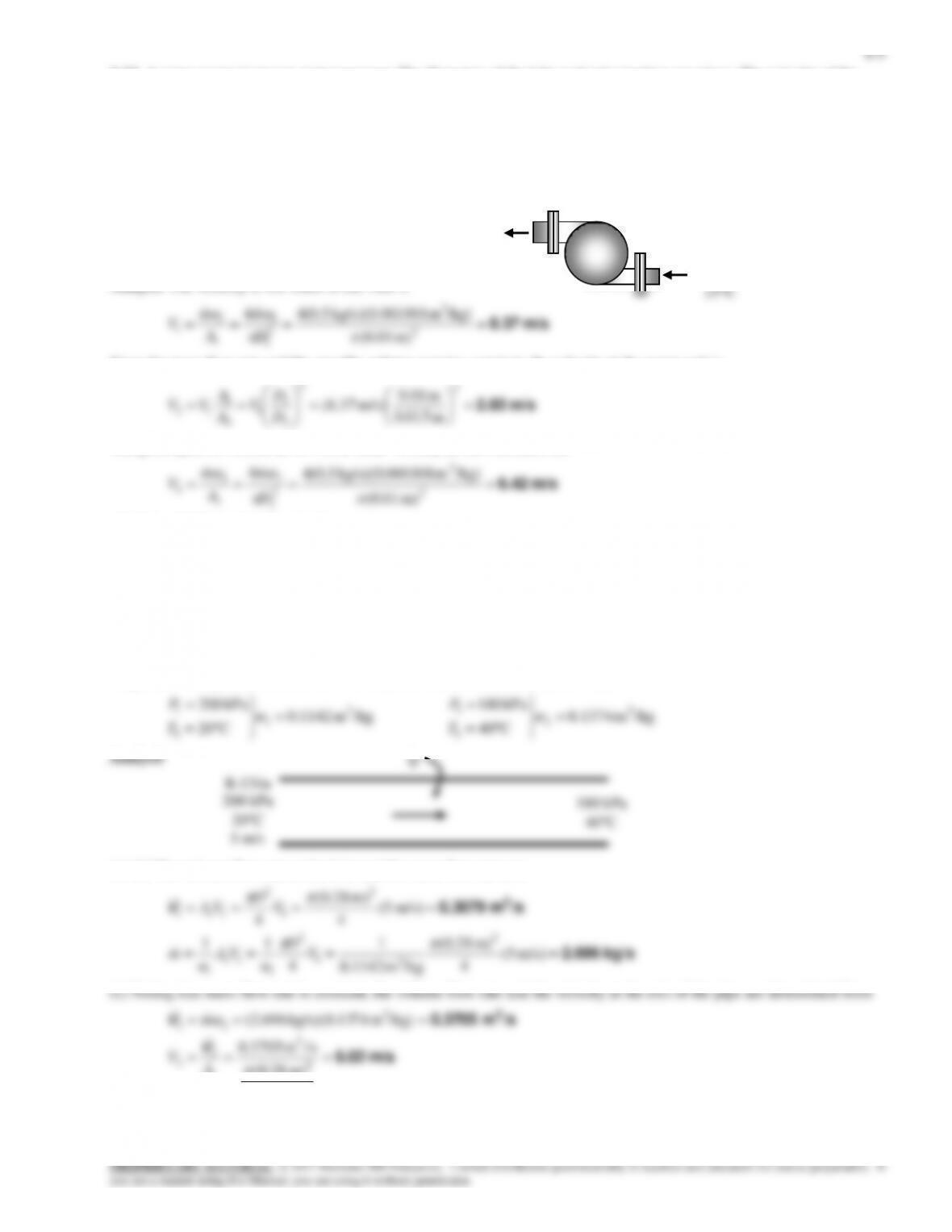
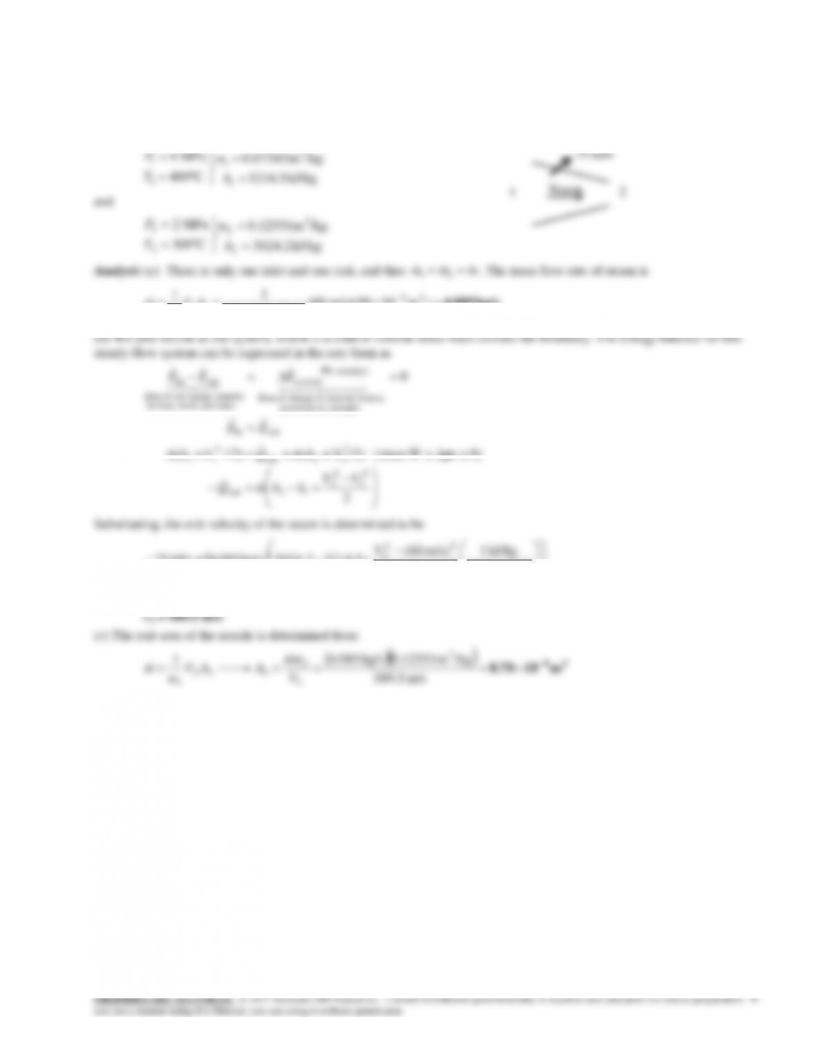
6-33 R-134a is decelerated in a diffuser from a velocity of 160 m/s. The exit velocity of R-134a and the mass flow rate of
the R-134a are to be determined.
Assumptions 1 This is a steady-flow process since there is no change with time. 2 Potential energy changes are negligible. 3
kJ/kg 262.46
vapor sat.
1
h
and
/kgm 0.031696
kPa 700
3
2
2
P
v
R-134a
1
2
6-20
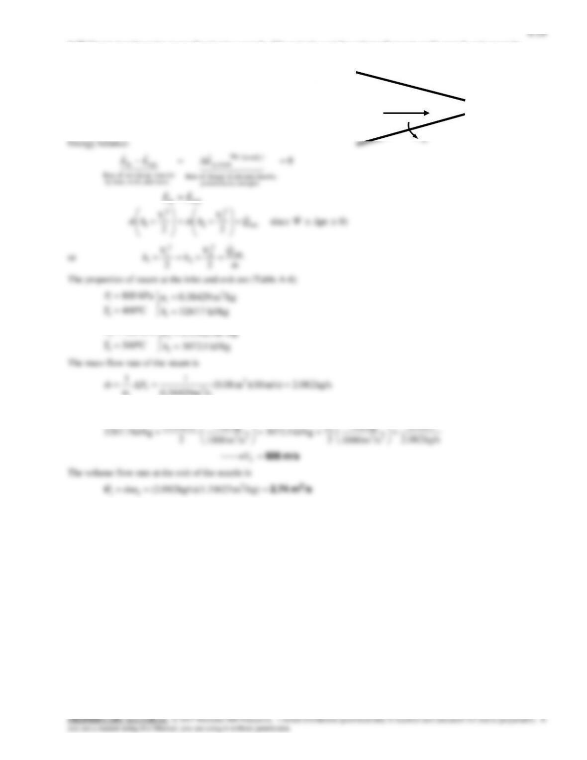
6-34 Steam is accelerated in a nozzle from a velocity of 60 m/s. The mass flow rate, the exit velocity, and the exit area of
the nozzle are to be determined.
Assumptions 1 This is a steady-flow process since there is no change with time. 2 Potential energy changes are negligible. 3
There are no work interactions.
Properties From the steam tables (Table A-6)
/kgm 0.07343
MPa 4
3
1
1
P
v
kg/s 4.085 )m1050)(m/s 06(
/kgm 0.07343
11 24
3
11
1
AVm
v
75 kJ/s