Unlock document.
This document is partially blurred.
Unlock all pages and 1 million more documents.
Get Access
22-41
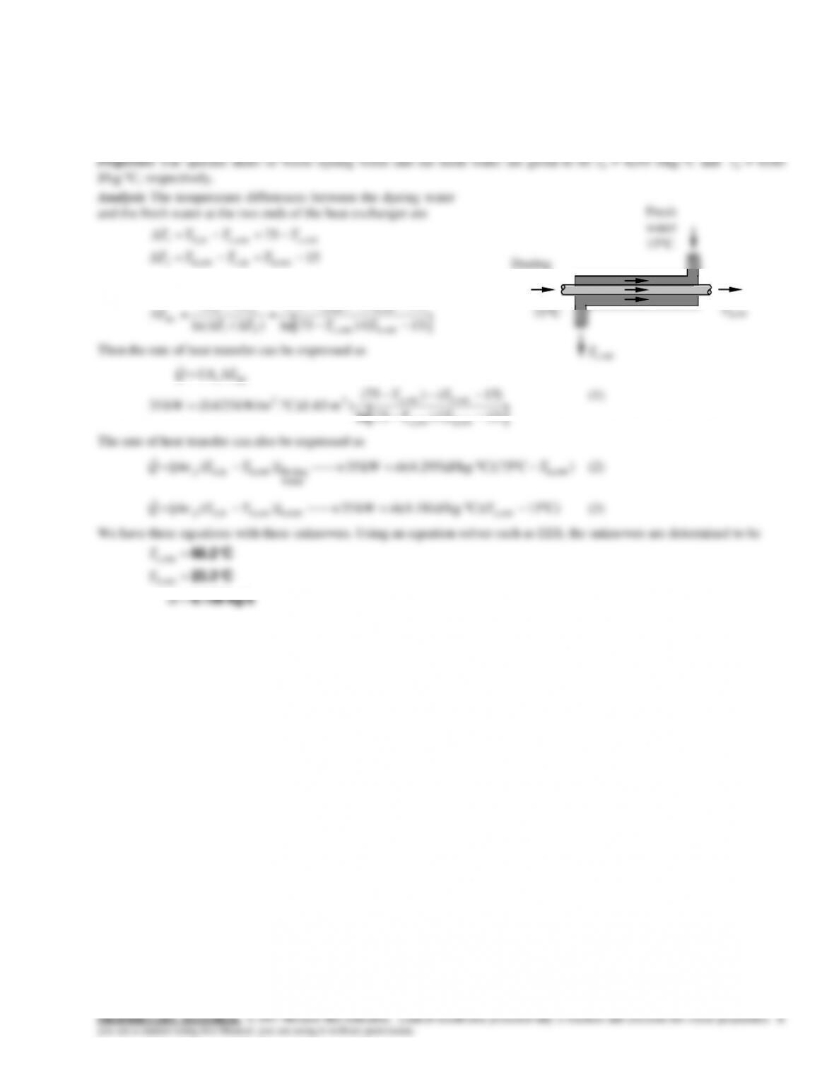
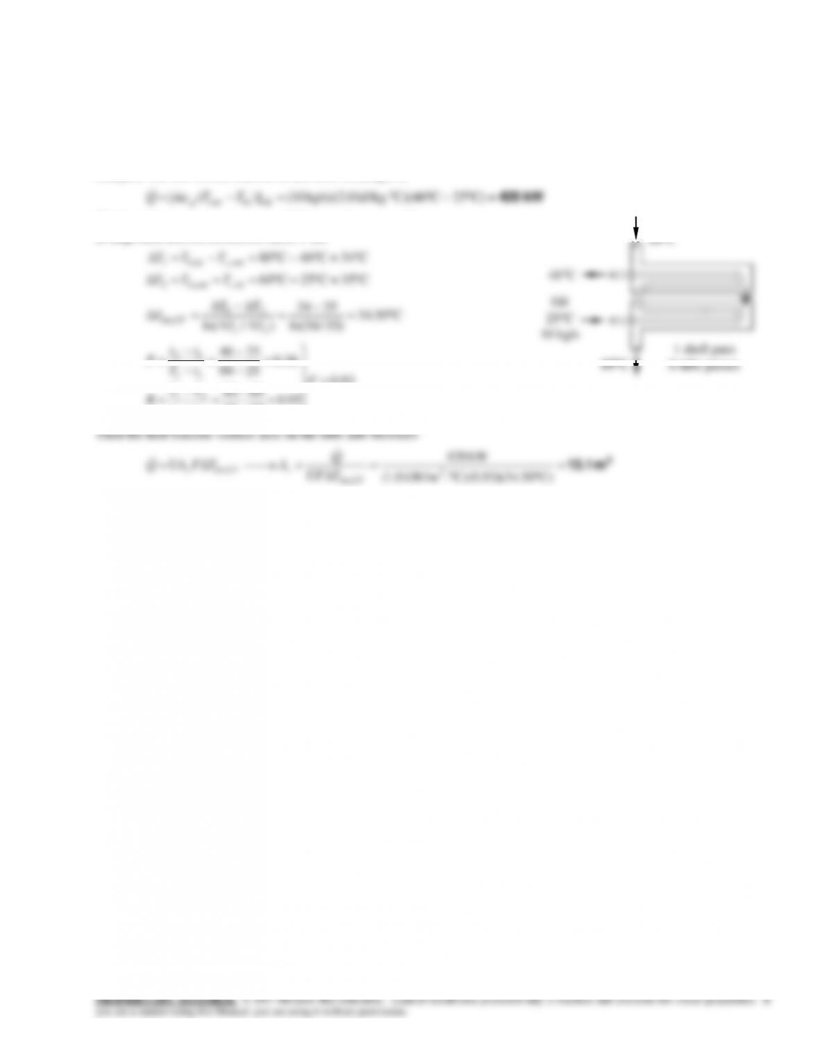
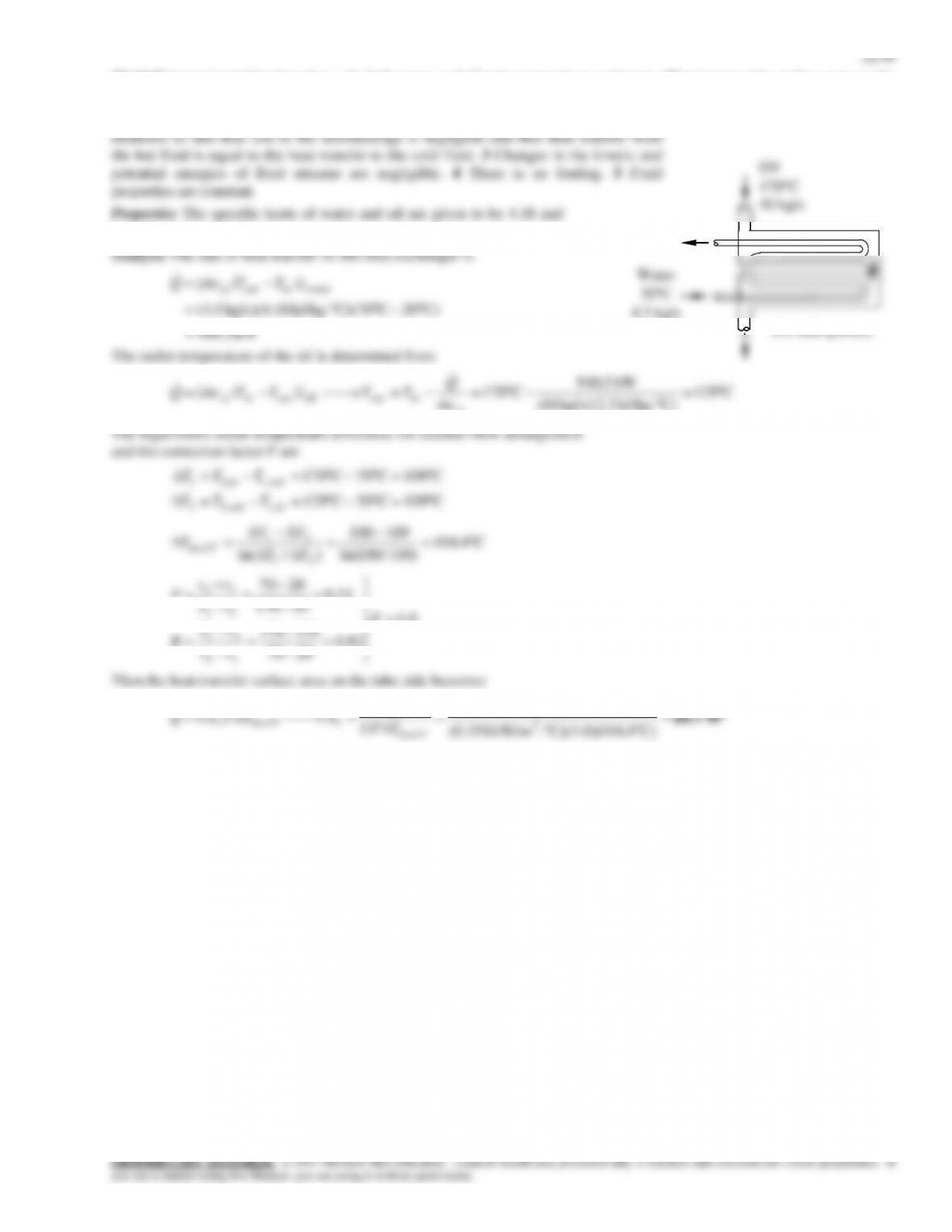
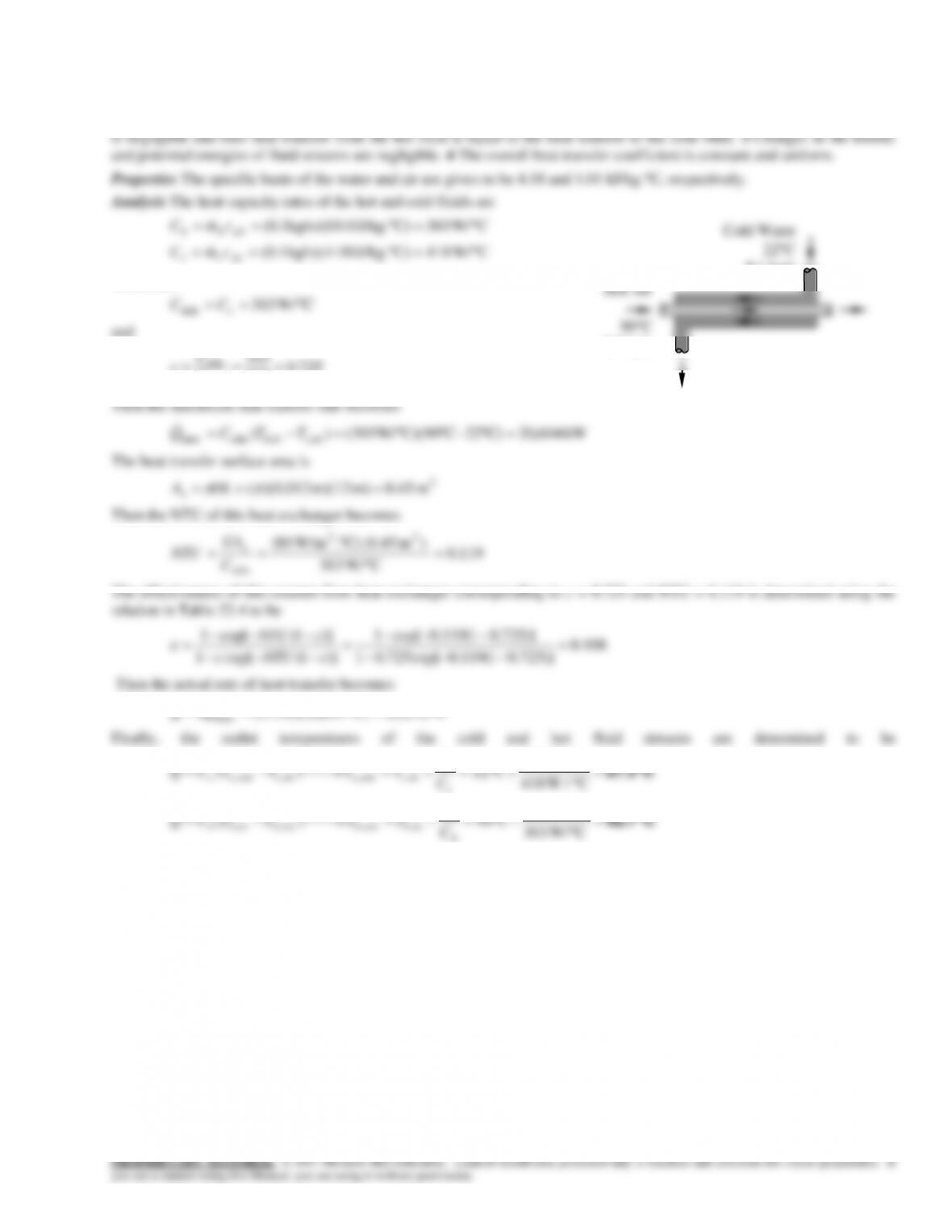
22-56 The waste dyeing water is to be used to preheat fresh water. The outlet temperatures of each fluid and the mass flow
rate are to be determined.
Assumptions 1 Steady operating conditions exist. 2 The heat exchanger is well-insulated so that heat loss to the surroundings
is negligible and thus heat transfer from the hot fluid is equal to the heat transfer to the cold fluid. 3 Changes in the kinetic
and potential energies of fluid streams are negligible. 4 There is no fouling. 5 Fluid properties are constant.
15
outh,inc,outh,2
TTTT
and
)15()75(
outh,outc,
21
TT
TT
Dyeing
water
Th,out
22-42
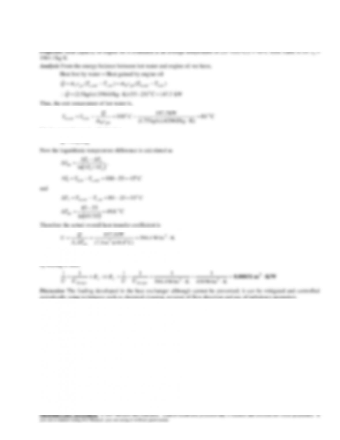
22-57 Counterflow double pipe heat exchanger with a surface area of 7.5 m2 and U = 450 W/m2·K is used to heat the engine
oil using water at 100C. It is to be determined if fouling has occurred in the heat exchanger over a period of time.
Assumptions 1 Steady state conditions exist. 2 Heat exchanger is well insulated. 3 Fluid properties remain constant.
K)J/kg4206(kg/s)75.1(
cm
phh
The heat transfer rate is calculated as
lmsTUAQ
C))(49.8m(7.5
o2
TA
lms
Since the actual overall heat transfer coefficient (394.4 W/m2·K ) is less than the designed value of the overall heat transfer
coefficient (450 W/m2·K), it can be concluded that fouling has occurred in the heat exchanger. The thermal resistance caused
periodically using techniques such as chemical cleaning, reversal of flow direction and use of turbulence promoters.
22-44
22-59 During an experiment, the inlet and exit temperatures of water and oil and the mass flow rate of water are measured.
The overall heat transfer coefficient based on the inner surface area is to be determined.
)25/65ln(
)/ln( 21
70.0
14.2
2055
45120
35.0
20120
2055
12
21
11
12
F
tt
TT
R
tT
tt
P
Water
3 kg/s
145C
24 tubes
22-45
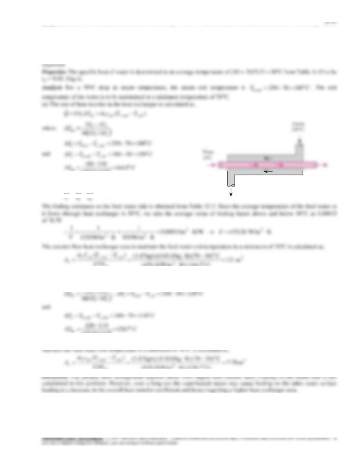
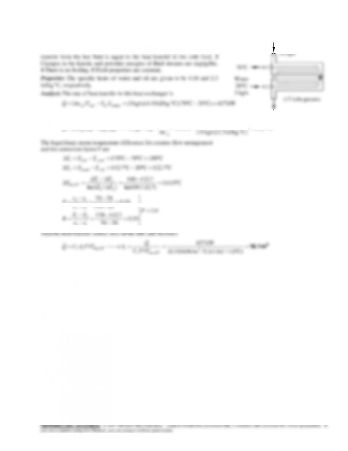
22-60 Oil is heated by water in a 1-shell pass and 6-tube passes heat exchanger. The rate of heat transfer and the heat transfer
surface area are to be determined.
Assumptions 1 Steady operating conditions exist. 2 The heat exchanger is well-insulated so that heat loss to the surroundings
is negligible and thus heat transfer from the hot fluid is equal to the heat transfer to the cold fluid. 3 Changes in the kinetic
and potential energies of fluid streams are negligible. 4 There is no fouling. 5 Fluid properties are constant.
Properties The specific heat of oil is given to be 2.0 kJ/kg.C.
Analysis The rate of heat transfer in this heat exchanger is
The logarithmic mean temperature difference for counter-flow
arrangement and the correction factor F are
C35=C25C60
C34=C46C80
,,2
,,1
incouth
outcinh
TTT
TTT
C50.34
)35/34ln(
3534
)/ln( 21
21
,
TT
TT
TCFlm
93.0
95.0
2546
6080
38.0
2580
2546
12
21
11
12
F
tt
TT
R
tT
tt
P
C)50.34(C)(0.93).kW/m 0.1(
2
,
CFlm
Water
80C
Oil
25C
10 kg/s
46C
1 shell pass
6 tube passes
60C
22-47
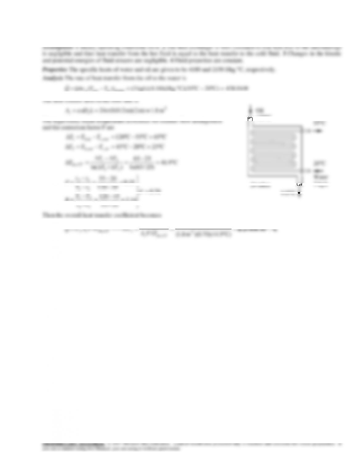
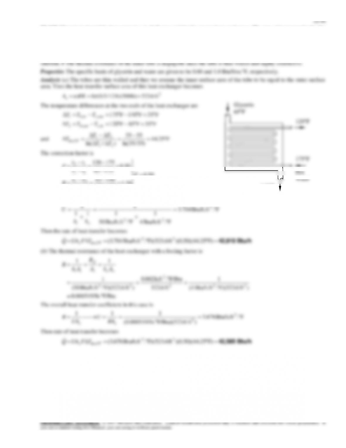
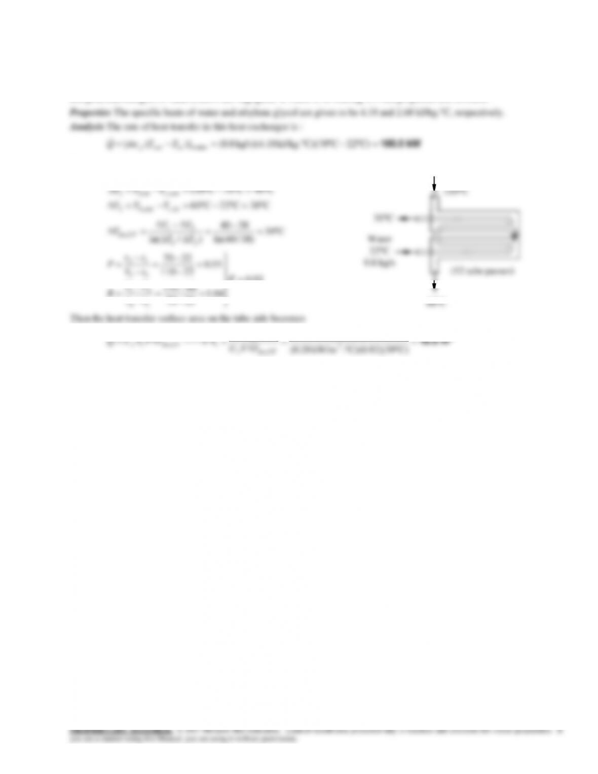
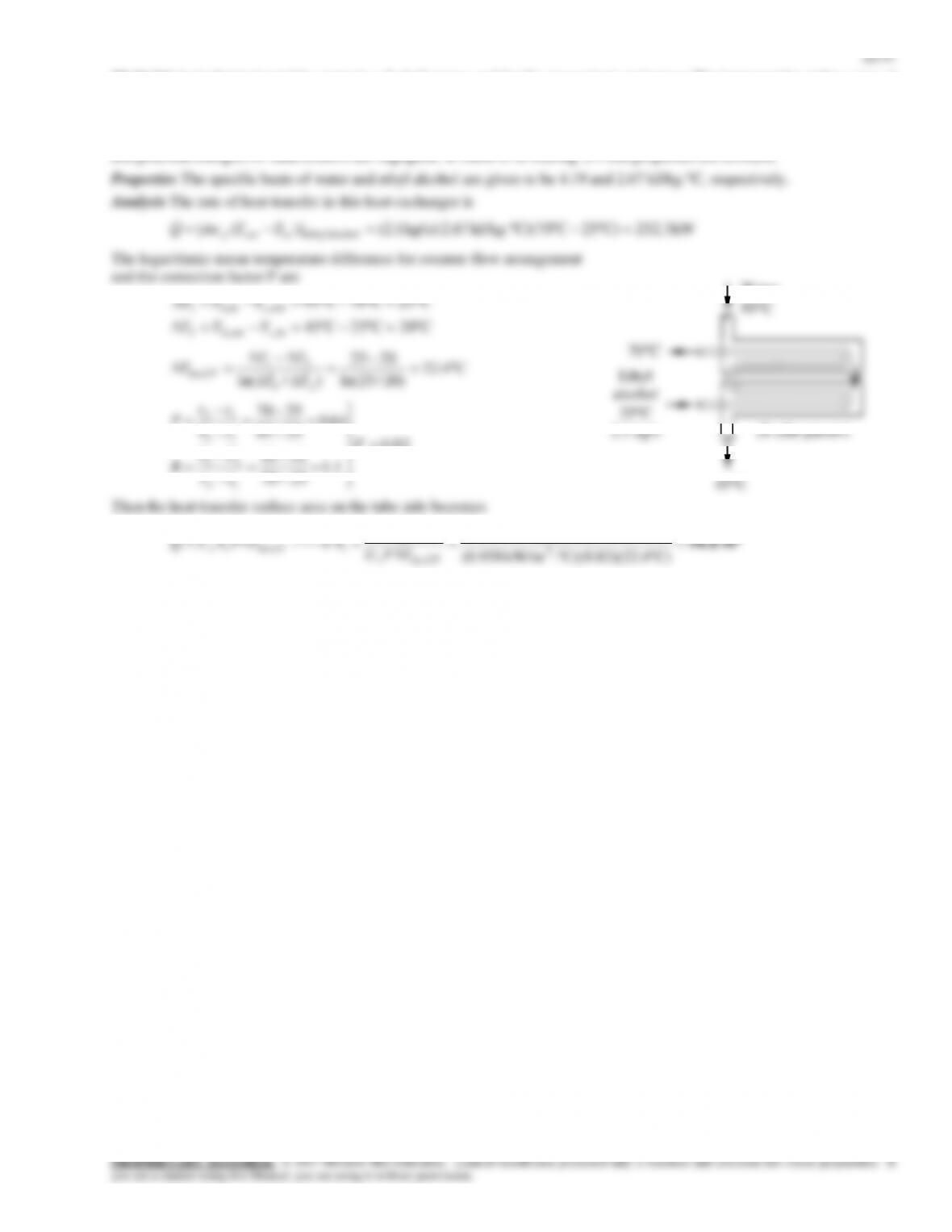
22-62 Water is heated by ethylene glycol in a 2-shell passes and 12-tube passes heat exchanger. The rate of heat transfer and
the heat transfer surface area on the tube side are to be determined.
Assumptions 1 Steady operating conditions exist. 2 The heat exchanger is well-insulated so that heat loss to the surroundings
is negligible and thus heat transfer from the hot fluid is equal to the heat transfer to the cold fluid. 3 Changes in the kinetic
and potential energies of fluid streams are negligible. 4 There is no fouling. 5 Fluid properties are constant.
The logarithmic mean temperature difference for counter-flow
arrangement and the correction factor F are
C40=C70C110
,,1
outcinh
TTT
)38/40ln(
)/ln( 21
92.0
04.1
2270
60110
55.0
22110
2270
12
21
11
12
F
tt
TT
R
tT
tt
P
C)39(C)(0.92).kW/m 28.0(
2
,
CFlmi
Ethylene
110C
Water
22C
0.8 kg/s
(12 tube passes)
60C
22-48
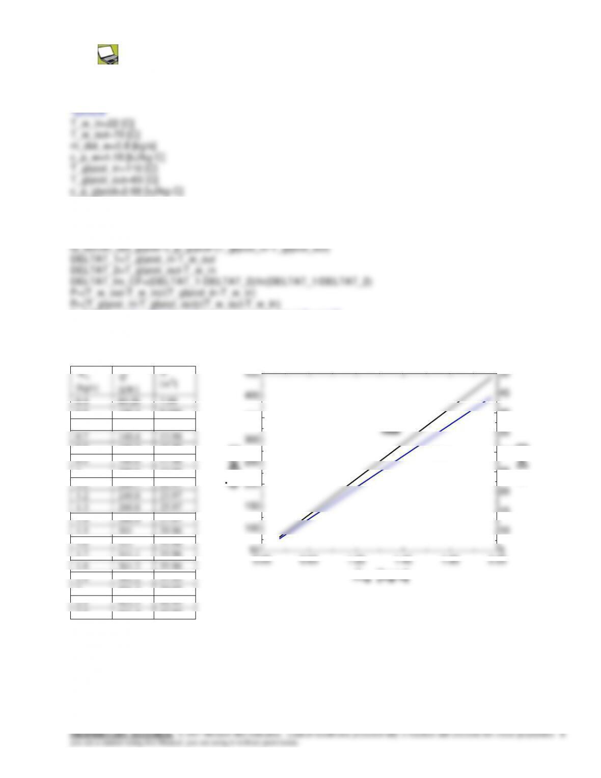
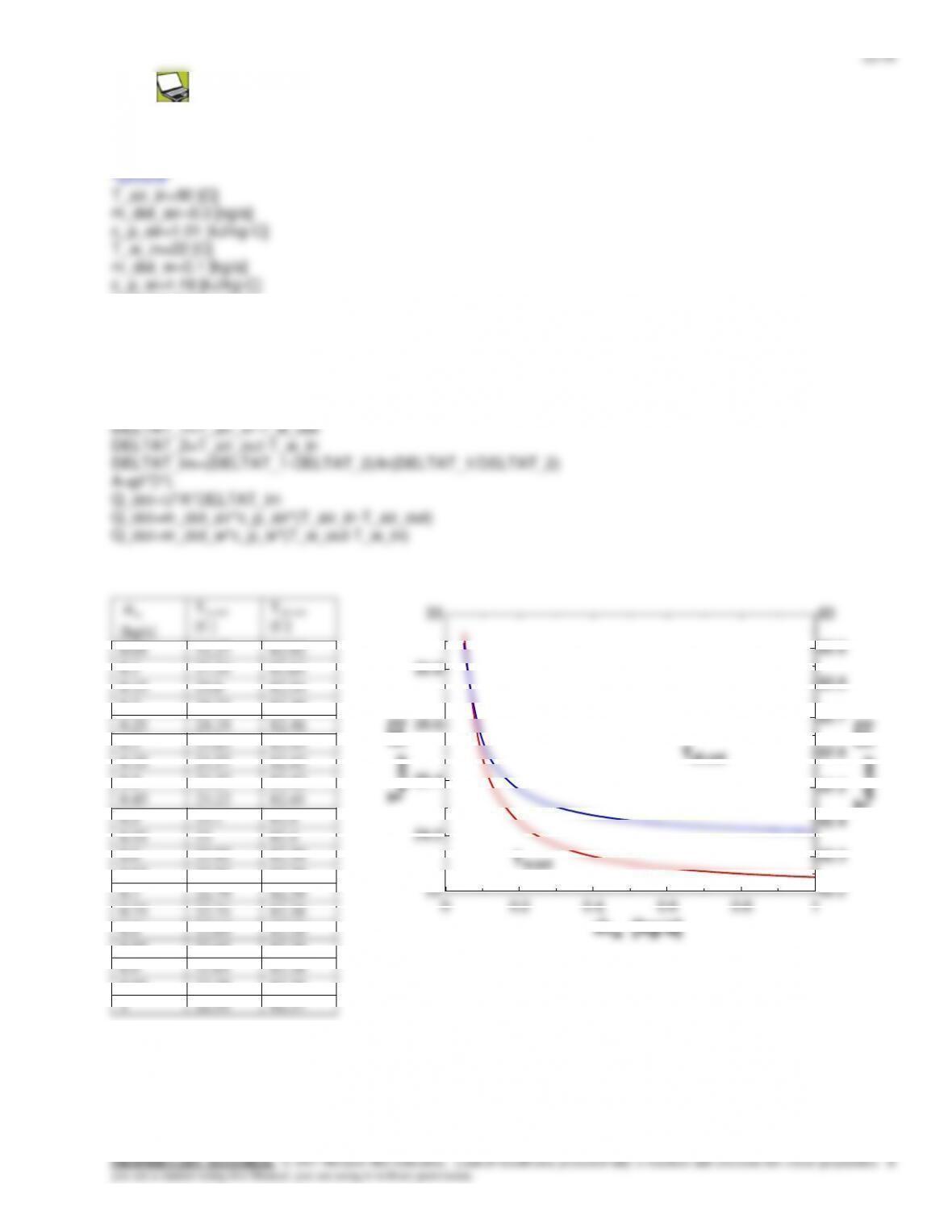
22-63 Prob. 22-62 is reconsidered. The effect of the mass flow rate of water on the rate of heat transfer and the tube-
side surface area is to be investigated.
Analysis The problem is solved using EES, and the solution is given below.
U=0.28 [kW/m^2-C]
"ANALYSIS"
Q_dot=m_dot_w*c_p_w*(T_w_out-T_w_in)
F=0.92 "from Fig. 22-19b of the text at the calculated P and R"
Q_dot=U*A*F*DELTAT_lm_CF
w
m
[kg/s]
Q
[kW]
A
[m2]
0.4
80.26
7.99
0.5
100.3
9.988
0.6
120.4
11.99
0.7
140.4
13.98
0.8
160.5
15.98
0.9
180.6
17.98
1
200.6
19.98
1.1
220.7
21.97
1.2
240.8
23.97
1.3
260.8
25.97
1.4
280.9
27.97
1.5
301
29.96
1.6
321
31.96
1.7
341.1
33.96
1.8
361.2
35.96
1.9
381.2
37.95
0.25 0.65 1.05 1.45 1.85 2.25
50
100
150
200
250
300
350
400
450
5
10
15
20
25
30
35
40
45
50
mw [kg/s]
Q [kW]
A [m2]
heat
area
22-50
22-65 Water is heated by hot oil in a 2-shell passes and 12-tube passes heat exchanger. The heat transfer surface area on the
tube side is to be determined.
Assumptions 1 Steady operating conditions exist. 2 The heat exchanger is
well-insulated so that heat loss to the surroundings is negligible and thus heat
The outlet temperature of the oil is determined from
C7.142
C)kJ/kg. kg/s)(2.3 10(
kW 627
C170)]([ oil
p
inoutoutinpcm
Q
TTTTcmQ
Oil
170C
10 kg/s
22-52
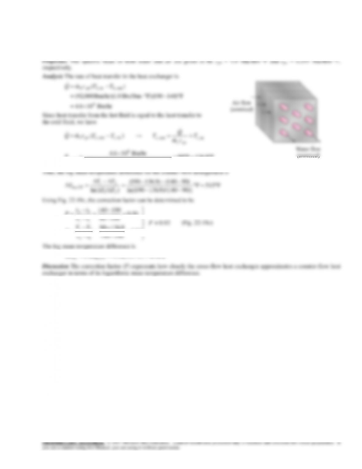
22-67E A single-pass cross-flow heat exchanger is used to cool jacket water using air. The log mean temperature difference
for the heat exchanger is to be determined.
Assumptions 1 Steady operating condition exists. 2 The heat exchanger is well-insulated so that heat loss to the surroundings
is negligible. 3 Fluid properties are constant. 4 Changes in the kinetic and potential energies of fluid streams are negligible.
pcc
cm
F9.136F90
)FBtu/lbm 245.0)(lbm/hr 000,400(
Btu/hr 106.4 6
out ,
c
T
22-53
The Effectiveness-NTU Method
22-68C The effectiveness of a heat exchanger is defined as the ratio of the actual heat transfer rate to the maximum possible
heat transfer rate and represents how closely the heat transfer in the heat exchanger approaches to maximum possible heat
transfer. Since the actual heat transfer rate can not be greater than maximum possible heat transfer rate, the effectiveness can
not be greater than one. The effectiveness of a heat exchanger depends on the geometry of the heat exchanger as well as the
flow arrangement.
highest effectiveness.
heat exchanger are determined from
)(
,,minmax
incinh
TTCQQ
22-55
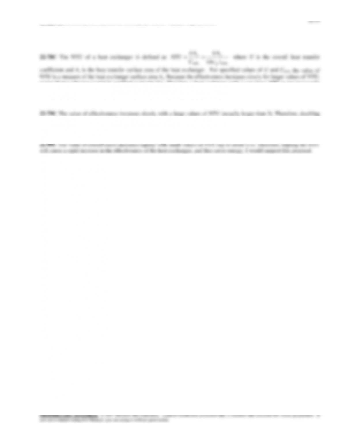
22-81 Hot water coming from the engine of an automobile is cooled by air in the radiator. The outlet temperature of the air
and the rate of heat transfer are to be determined.
Assumptions 1 Steady operating conditions exist. 2 The heat exchanger is well-insulated so that heat loss to the surroundings
is negligible and thus heat transfer from the hot fluid is equal to the heat transfer to the cold fluid. 3 Changes in the kinetic
and potential energies of fluid streams are negligible. 4 Fluid properties are constant.
which is the smaller of the two heat capacity rates. Noting that the heat
capacity rate of the air is the smaller one, the outlet temperature of the air is
22-82 Inlet and outlet temperatures of the hot and cold fluids in a double-pipe heat exchanger are given. It is to be determined
whether this is a parallel-flow or counter-flow heat exchanger and the effectiveness of it.
Analysis This is a counter-flow heat exchanger because in the parallel-flow heat exchangers the outlet temperature of the cold
)(
)(
,,
,,min
max incinhh
incinh
TTC
TTC
Q
22-83E Inlet and outlet temperatures of the hot and cold fluids in a double-pipe heat exchanger are given. It is to be
determined the fluid, which has the smaller heat capacity rate and the effectiveness of the heat exchanger.
Analysis Hot water has the smaller heat capacity rate since it experiences a greater temperature change. The effectiveness of
)(
)(
,,
,,min
max incinhh
incinh
TTC
TTC
Q
Air
30C
10 kg/s
22-57
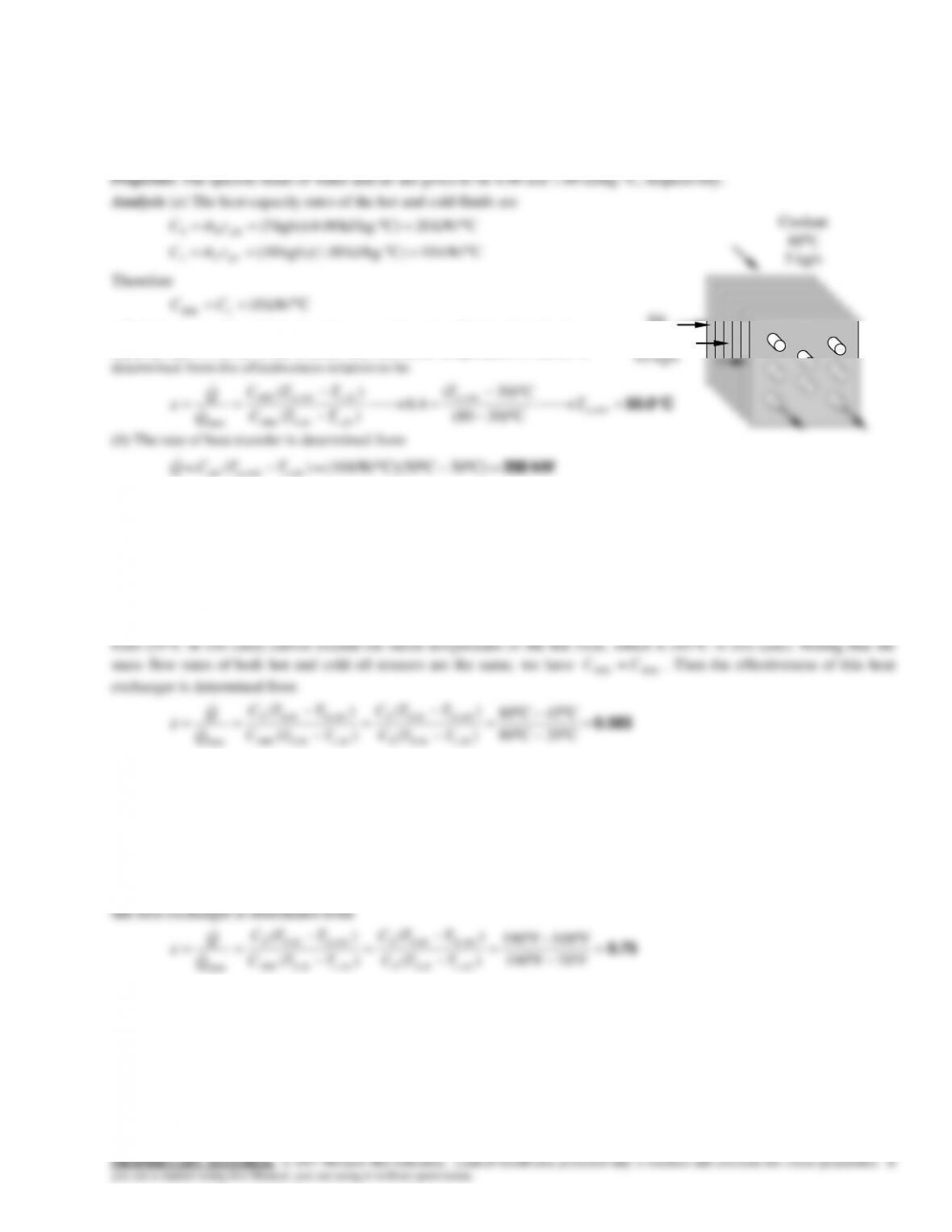
22-85 Water is heated by solar-heated hot air in a heat exchanger. The mass flow rates and the inlet temperatures are given.
The outlet temperatures of the water and the air are to be determined.
Assumptions 1 Steady operating conditions exist. 2 The heat exchanger is well-insulated so that heat loss to the surroundings
C W/418C)J/kg. kg/s)(4180 (0.1
pccc
cmC
Therefore,
C W/303
min c
CC
and
725.0
418
303
max
min C
C
c
W2.2225 W),604(0.108)(20
max QQ
C82.7
C27.3
C W/303
W2.2225
C90)(
C/ W418
W2.2225
C22)(
,,,,
,,,,
h
inhouthouthinhh
c
incoutcincoutcc
C
Q
TTTTCQ
C
Q
TTTTCQ
Hot Air
90C
0.3 kg/s
22C
0.1 kg/s
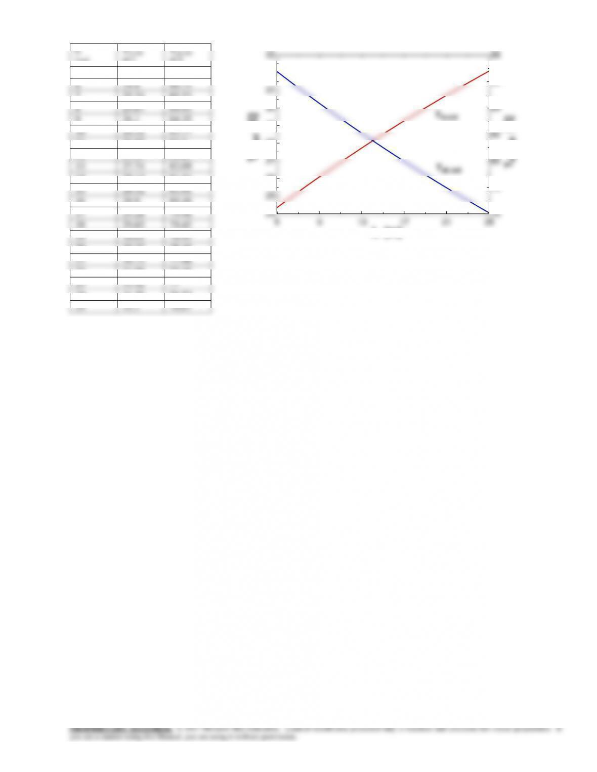
22-59
L
[m]
Tw,out
[C]
Tair,out
[C]
5
24.35
86.76
6
24.8
86.14
7
25.24
85.53
8
25.67
84.93
9
26.1
84.35
10
26.52
83.77
11
26.93
83.2
12
27.34
82.64
13
27.74
82.09
14
28.13
81.54
15
28.52
81.01
16
28.9
80.48
17
29.28
79.96
18
29.65
79.45
19
30.01
78.95
20
30.37
78.45
21
30.73
77.96
22
31.08
77.48
23
31.42
77
24
31.76
76.53
25
32.1
76.07
5 9 13 17 21 25
24
25
26
27
28
29
30
31
32
33
76
78
80
82
84
86
88
L [m]
Tw,out [C]
Tair,out [C]
Tw,out
Tair,out
22-60
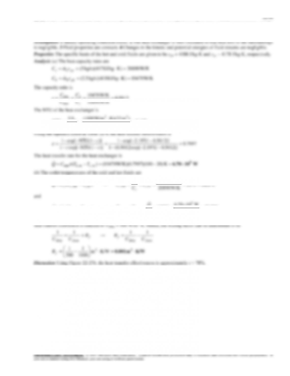
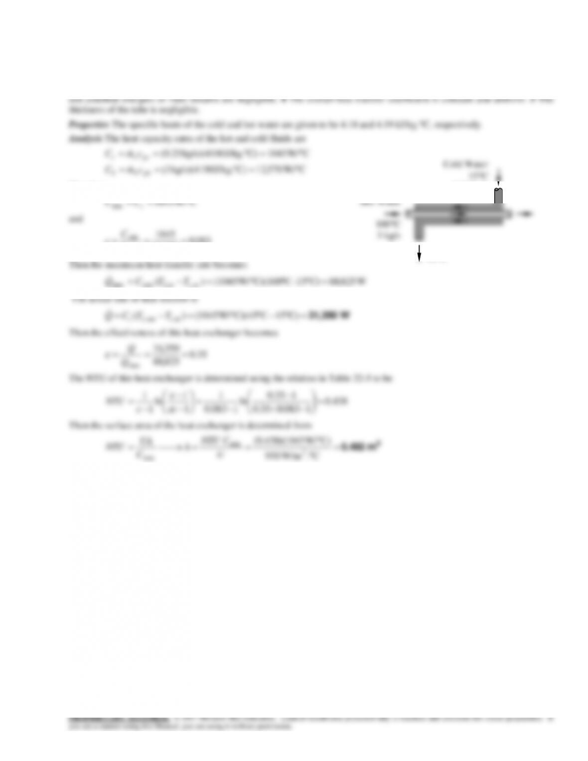
22-87 Cold water is heated by hot water in a heat exchanger. The net rate of heat transfer and the heat transfer surface area of
the heat exchanger are to be determined.
Assumptions 1 Steady operating conditions exist. 2 The heat exchanger is well-insulated so that heat loss to the surroundings
is negligible and thus heat transfer from the hot fluid is equal to the heat transfer to the cold fluid. 3 Changes in the kinetic
CW/ 570,12C)J/kg. kg/s)(4190 (3
phhh
cmC
Therefore,
CW/ 1045
min c
CC
and
083.0
570,12
1045
max
min C
C
c
Hot Water
100C
3 kg/s
15C
0.25 kg/s
45C


