22-1
Solutions Manual
for
Fundamentals of Thermal Fluid Sciences
5th Edition
Yunus A. Çengel, John M. Cimbala, Robert H. Turner
McGraw-Hill, 2017
Chapter 22
HEAT EXCHANGERS
PROPRIETARY AND CONFIDENTIAL
This Manual is the proprietary property of McGraw-Hill Education and protected by copyright and other
state and federal laws. By opening and using this Manual the user agrees to the following restrictions,
and if the recipient does not agree to these restrictions, the Manual should be promptly returned
unopened to McGraw-Hill Education: This Manual is being provided only to authorized professors
and instructors for use in preparing for the classes using the affiliated textbook. No other use or
distribution of this Manual is permitted. This Manual may not be sold and may not be distributed
to or used by any student or other third party. No part of this Manual may be reproduced,
displayed or distributed in any form or by any means, electronic or otherwise, without the prior
written permission of McGraw-Hill Education.
22-2
Types of Heat Exchangers
In parallel flow, both the hot and cold fluids enter the heat exchanger at the same end and move in the same direction. In
counter-flow, the hot and cold fluids enter the heat exchanger at opposite ends and flow in opposite direction. In cross-flow,
the hot and cold fluid streams move perpendicular to each other.
transfer surface area to its volume which is called the area density. The area density for double-pipe heat exchanger can not
be in the order of 700. Therefore, it can not be classified as a compact heat exchanger.
ceramic wire mash. Hot and cold fluids flow through this porous mass alternately. Heat is transferred from the hot fluid to
the matrix of the regenerator during the flow of the hot fluid and from the matrix to the cold fluid. Thus the matrix serves as
a temporary heat storage medium. The dynamic type regenerator involves a rotating drum and continuous flow of the hot
and cold fluid through different portions of the drum so that any portion of the drum passes periodically through the hot
stream, storing heat and then through the cold stream, rejecting this stored heat. Again the drum serves as the medium to
transport the heat from the hot to the cold fluid stream.
the shell to enhance heat transfer and to maintain uniform spacing between the tubes. Baffles disrupt the flow of fluid, and an
increased pumping power will be needed to maintain flow. On the other hand, baffles eliminate dead spots and increase heat
transfer rate.
22-5C In counter-flow heat exchangers, the hot and the cold fluids move parallel to each other but both enter the heat
exchanger at opposite ends and flow in opposite direction. In cross-flow heat exchangers, the two fluids usually move
perpendicular to each other. The cross-flow is said to be unmixed when the plate fins force the fluid to flow through a
particular interfin spacing and prevent it from moving in the transverse direction. When the fluid is free to move in the
transverse direction, the cross-flow is said to be mixed.
22-3
The Overall Heat Transfer Coefficient
wall to the cold liquid again by convection.
22-7C When the wall thickness of the tube is small and the thermal conductivity of the tube material is high, which is usually
the case, the thermal resistance of the tube is negligible.
22-8C The heat transfer surface areas are
LDALDA oi 21 and
. When the thickness of inner tube is small, it is
reasonable to assume
soi AAA
.
22-9C The effect of fouling on a heat transfer is represented by a fouling factor Rf. Its effect on the heat transfer coefficient is
accounted for by introducing a thermal resistance Rf /As. The fouling increases with increasing temperature and decreasing
velocity.
Another form of fouling is corrosion and other chemical fouling. Heat exchangers may also be fouled by the growth of algae
in warm fluids. This type of fouling is called the biological fouling. Fouling represents additional resistance to heat transfer
and causes the rate of heat transfer in a heat exchanger to decrease, and the pressure drop to increase.
resistance of the tube is negligible and the inner and the outer surfaces of the tube are almost identical (
so AAAi
). Then
the overall heat transfer coefficient of a heat exchanger can be determined to from U = (1/hi + 1/ho)-1
22-4
22–13E The overall heat transfer coefficients based on the outer and inner surfaces for a heat exchanger are to be determined.
Assumptions 1 Steady operating condition exists. 2 Thermal properties are constant.
Properties The conductivity of the tube material is given to be 0.5 Btu/hr·ft·°F.
Analysis The overall heat transfer coefficient based on the outer surface is
1
111
FftBtu/hr 6.48 2
3
10
2
)5.0(2
50
Discussion The two overall heat transfer coefficients differ significantly with Ui larger than Uo by a factor of 1.5. The overall
heat transfer coefficient ratio can be expressed as
11
o
o
i
D
A
U
22-5
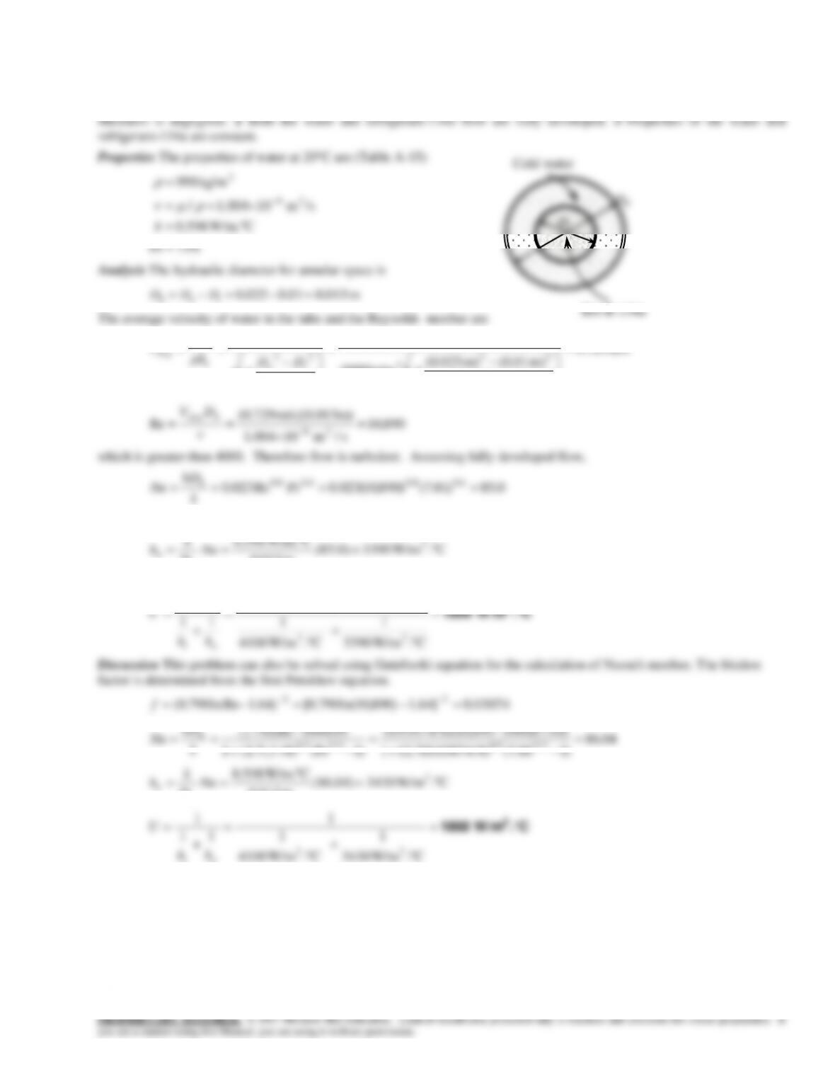
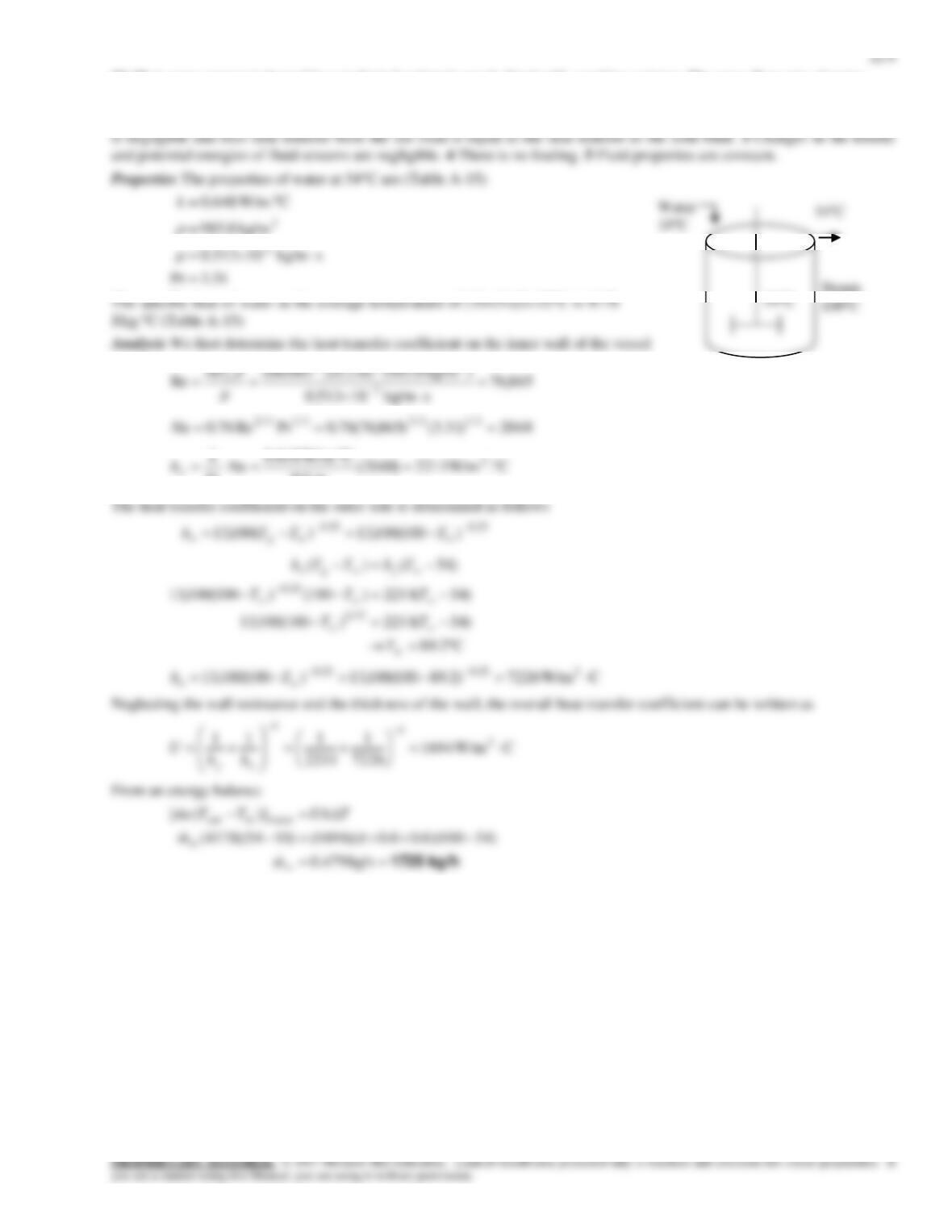
22–14 Refrigerant-134a is cooled by water in a double-pipe heat exchanger. The overall heat transfer coefficient is to be
determined.
Assumptions 1 The thermal resistance of the inner tube is negligible since the tube material is highly conductive and its
kg/s 3.0
m
m
and
C W/m.598.0 2
k
22-6
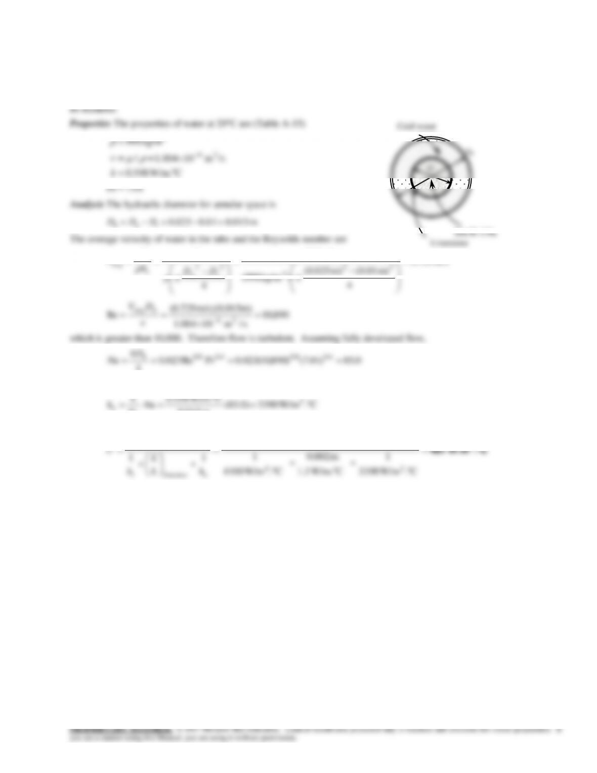
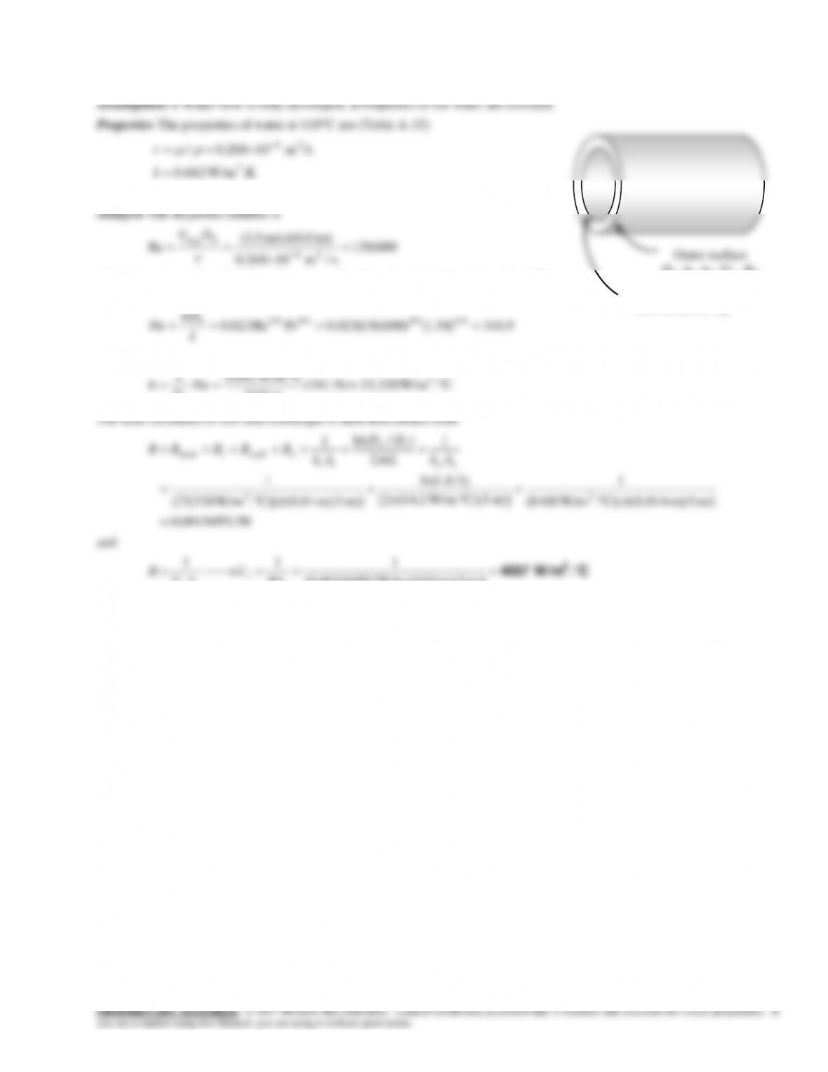
22–15 Refrigerant-134a is cooled by water in a double-pipe heat exchanger. The overall heat transfer coefficient is to be
determined.
Assumptions 1 The thermal resistance of the inner tube is negligible since the tube material is highly conductive and its
thickness is negligible. 2 Both the water and refrigerant-134a flows are fully developed. 3 Properties of the water and
refrigerant-134a are constant. 4 The limestone layer can be treated as a plain layer since its thickness is very small relative to
22-7
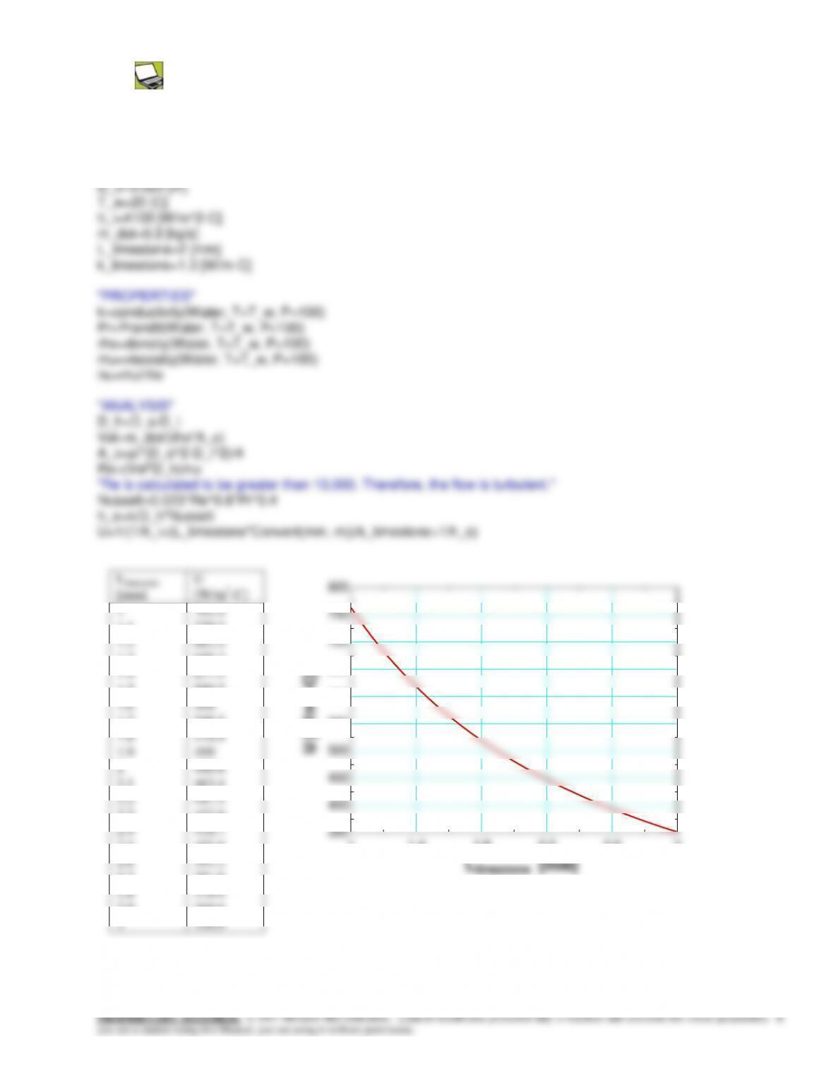
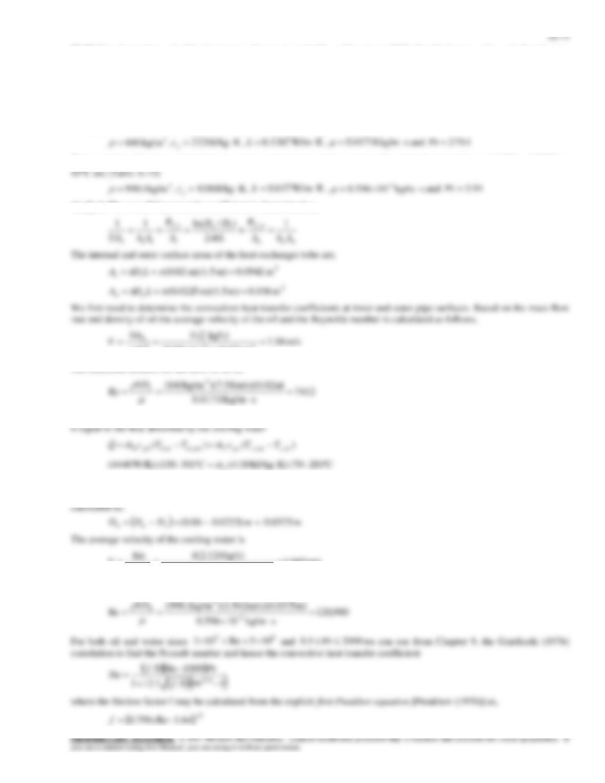
22–16 Prob. 22–15 is reconsidered. The overall heat transfer coefficient as a function of the limestone thickness is to be
plotted.
Analysis The problem is solved using EES, and the solution is given below.
“GIVEN”
D_i=0.010 [m]
2
2.1
2.2
2.3
2.4
480.6
463.4
447.5
432.6
418.7
350
400
450
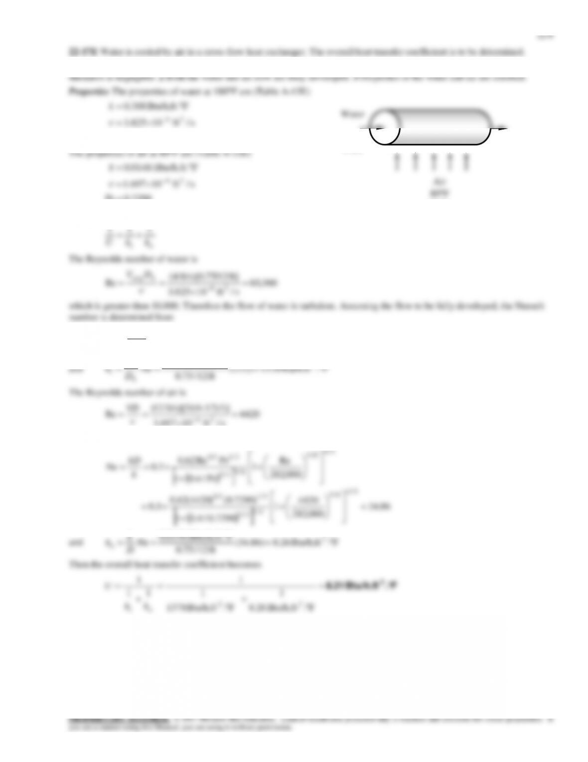
Assumptions 1 The thermal resistance of the inner tube is negligible since the tube material is highly conductive and its
15.2Pr
The properties of air at 80F are (Table A-22E)
7290.0Pr
s/ft 10697.1
FBtu/h.ft. 01481.0
24
k
Analysis The overall heat transfer coefficient can be determined from
111
222)15.2()360,65(023.0PrRe023.0 4.08.04.08.0 k
hD
Nu h
FBtu/h.ft. 388.0 2
k
180F
4 ft/s
Air
80F
12 ft/s
22–11
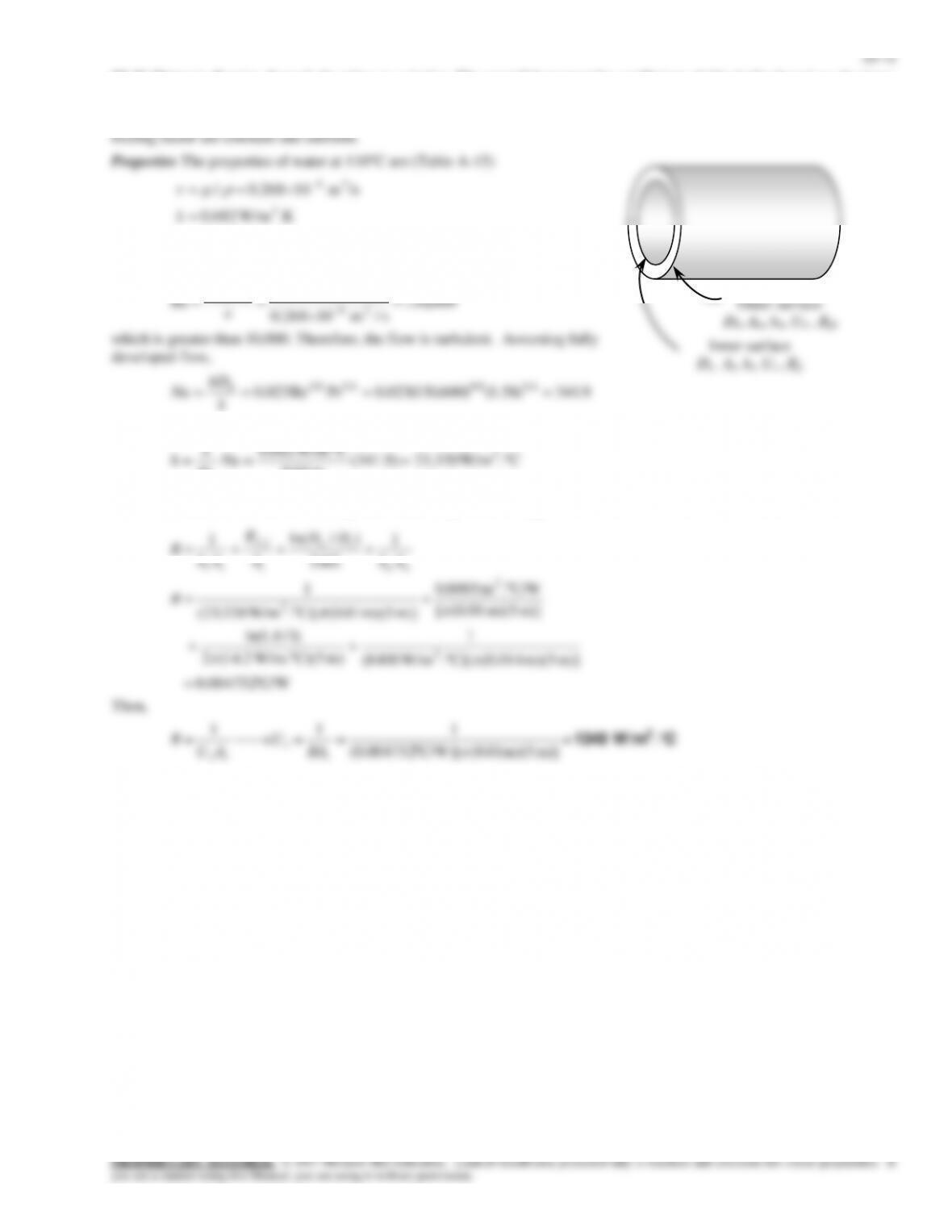
22–20 Water flows through the tubes in a boiler. The overall heat transfer coefficient of this boiler based on the inner surface
area is to be determined.
58.1Pr
Analysis The Reynolds number is
600,130
s/m 10268.0
m) m/s)(0.01 5.3(
Re 26
avg
h
DV
which is greater than 10,000. Therefore, the flow is turbulent. Assuming fully
developed flow,
hD
and
C W/m.682.0 2
k
Outer surface
D0, A0, h0, U0 , Rf0
Inner surface
Di, Ai, hi, Ui , Rfi
22–13
22-22 Prob. 22-21 is reconsidered. The overall heat transfer coefficient based on the inner surface as a function of
fouling factor is to be plotted.
Analysis The problem is solved using EES, and the solution is given below.
Vel=3.5 [m/s]
L=5 [m]
k_pipe=14.2 [W/m-C]
D_i=0.010 [m]
D_o=0.014 [m]
22–15
For oil,
03429.064.1)7412ln(79.0 2
f
22–16
Analysis of Heat Exchangers
they can be modeled as steady-flow devices. As such , the mass flow rate of each fluid remains constant and the fluid
properties such as temperature and velocity at any inlet and outlet remain constant. The kinetic and potential energy changes
are negligible. The specific heat of a fluid can be treated as constant in a specified temperature range. Axial heat conduction
along the tube is negligible. Finally, the outer surface of the heat exchanger is assumed to be perfectly insulated so that there
is no heat loss to the surrounding medium and any heat transfer thus occurs is between the two fluids only.
exchanger.
equal to the temperature drop of the hot fluid.
22–18
The Log Mean Temperature Difference Method
21
TT
TT
mean temperature difference is defined as
2
+
=21
am
TT
T
. The logarithmic mean temperature difference Tlm is obtained
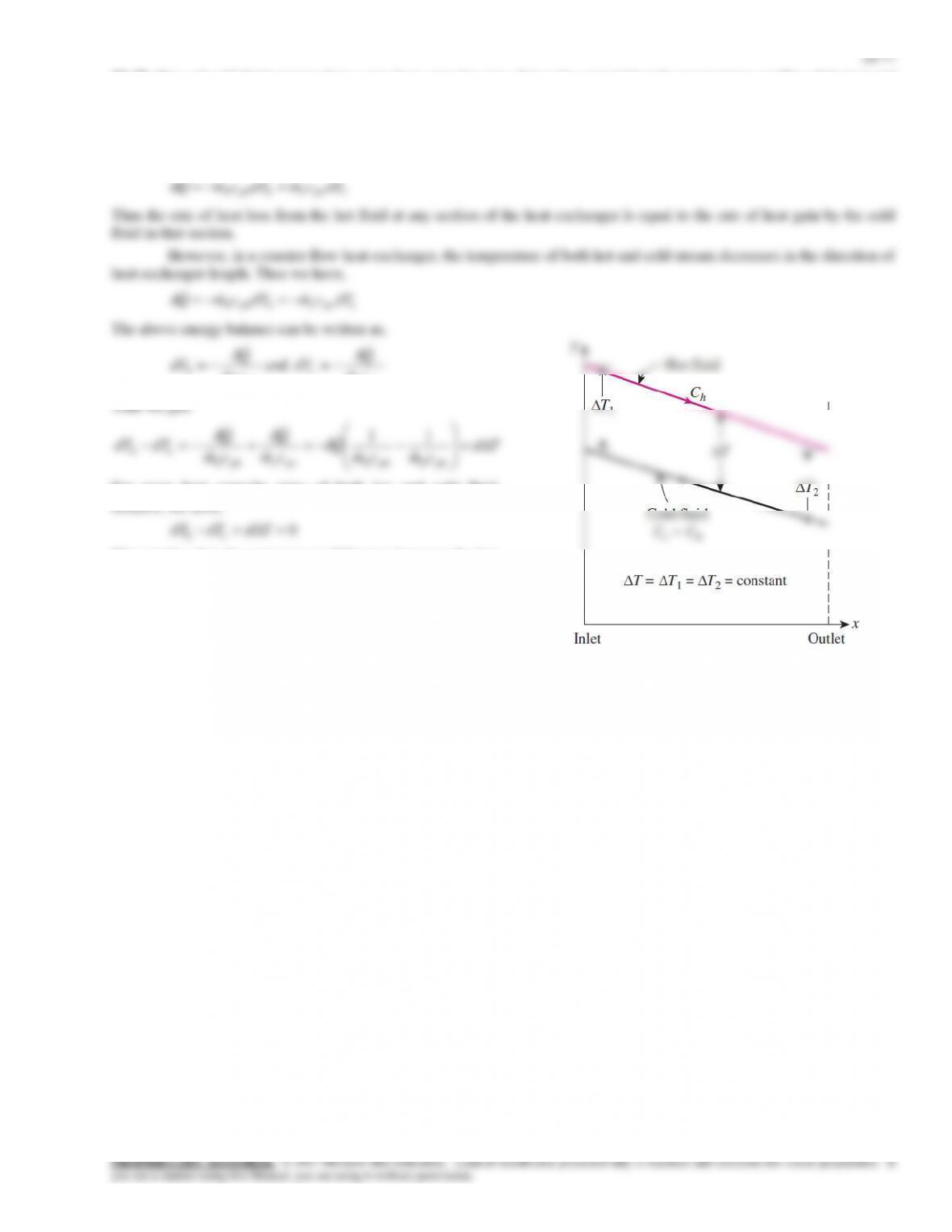
temperature of the hot fluid decreases and the temperature of the cold fluid increases along the heat exchanger. But the
temperature of the cold fluid can never exceed that of the hot fluid. In case of the counter-flow heat exchangers the hot and
cold fluids enter the heat exchanger from the opposite ends and the outlet temperature of the cold fluid may exceed the outlet
temperature of the hot fluid.
)/ln( 21
21
TT
TT
from the figures, and finally the surface area of the heat exchanger from
CFlm
UAFDTQ ,
=
heat exchanger in terms of its logarithmic mean temperature difference. F cannot be greater than unity.
effectiveness-NTU method should be used.
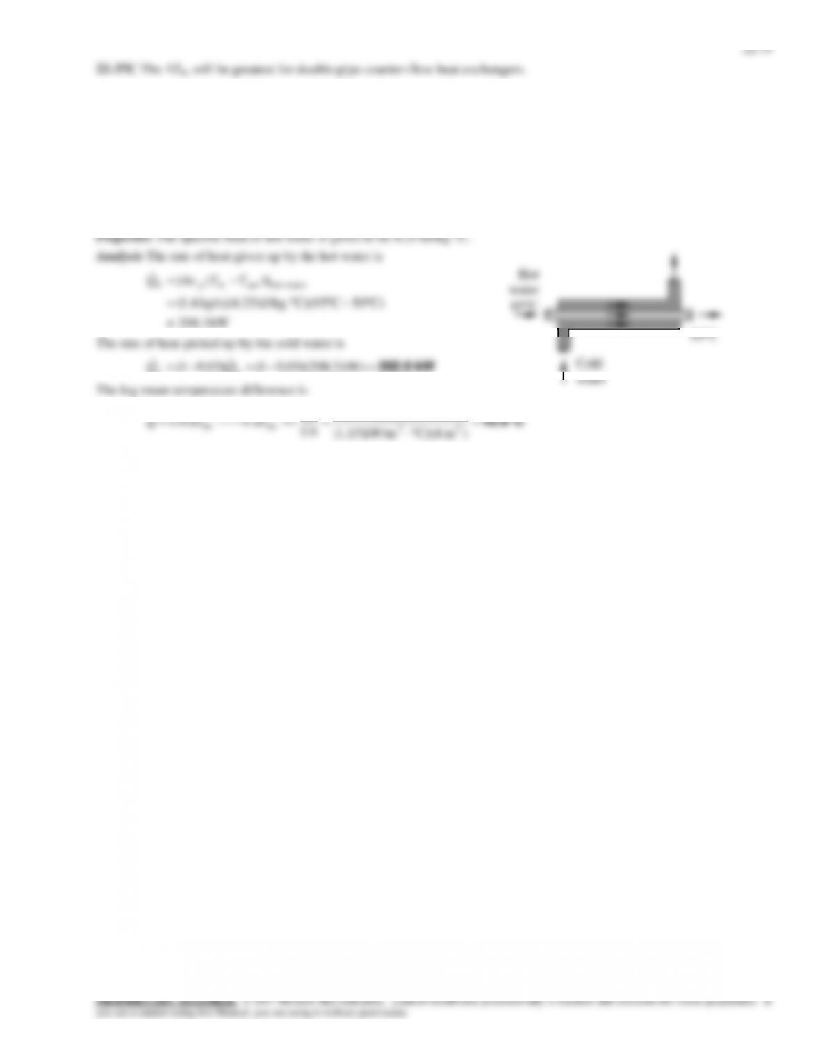
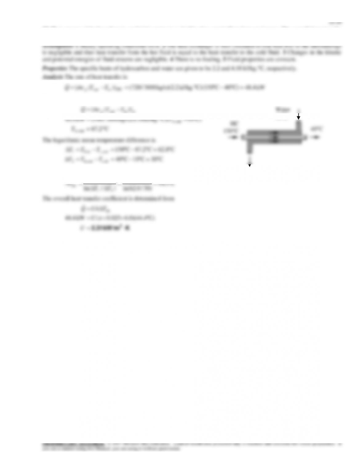
22–38 Water is heated in a double-pipe, parallel-flow uninsulated heat exchanger by geothermal water. The rate of heat
transfer to the cold water and the log mean temperature difference for this heat exchanger are to be determined.
Assumptions 1 Steady operating conditions exist. 2 Changes in the kinetic and potential energies of fluid streams are
negligible. 4 There is no fouling. 5 Fluid properties are constant.