15–56
15–89
Solution The bottom surface of a plastic boat is approximated as a flat surface. The friction drag exerted on the
bottom surface of the boat by water and the power needed to overcome it are to be determined.
Assumptions 1 The flow is steady and incompressible. 2 The water is calm (no significant currents or waves). 3 The
002517.0
)10195.2(
074.0
Re
074.0
5/175/1
L
f
C
N 589
N 589.4
kg.m/s 1
N 1
2
m/s) )(45/3.6kg/m (999.1
]m 25.1)[002517.0(
22
23
2
2
V
ACF fD
Noting that power is force times velocity, the power needed to overcome this drag force is
kW 7.37
m/sN 1000
kW 1
m/s) 6.3/N)(45 4.589(
drag VFW D
Discussion Note that the calculated drag force (and the power required to overcome it) is relatively small. This is not
surprising since the drag force for blunt bodies (including those partially immersed in a liquid) is almost entirely due to
pressure drag, and the friction drag is practically negligible compared to the pressure drag.
15–90
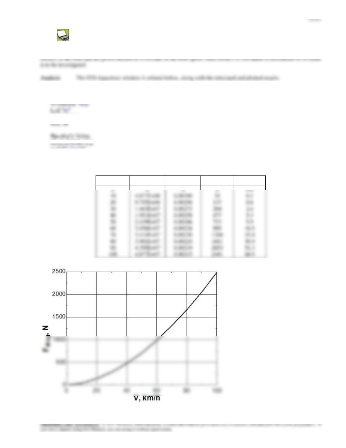
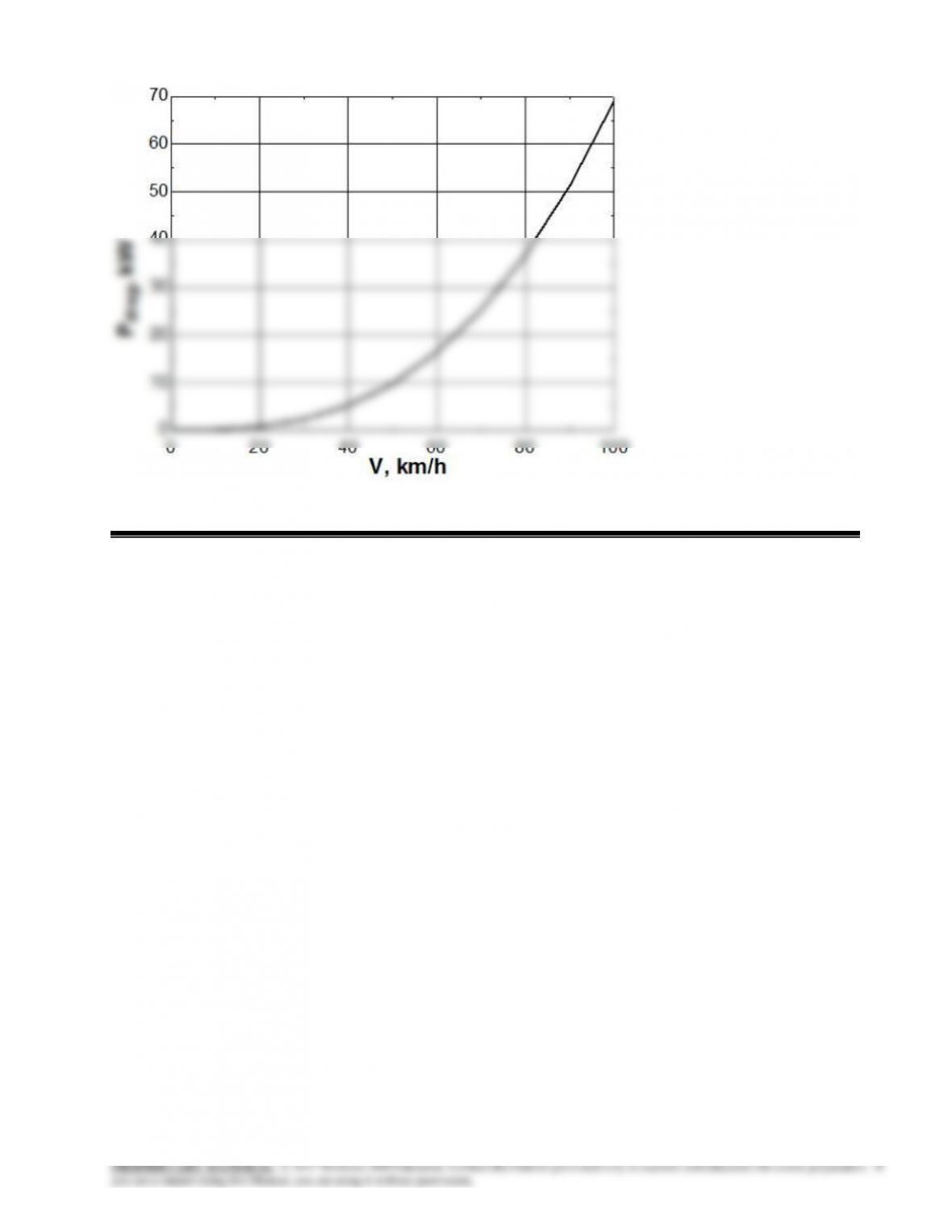
Solution The previous problem is reconsidered. The effect of boat speed on the drag force acting on the bottom
rho=999.1 “kg/m3″
mu=1.138E-3 “m2/s”
W=1.5 “m”
g=9.81 “m/s2″
F=Cf*A*(rho*V^2)/2 “N”
P_drag=F*V/1000 “kW“
V, km/h
Re
Cf
Fdrag, N
Pdrag, kW
0
10
20
30
40
50
60
70
80
90
100
0
4.877E+06
9.755E+06
1.463E+07
1.951E+07
2.439E+07
2.926E+07
3.414E+07
3.902E+07
4.390E+07
4.877E+07
0
0.00340
0.00296
0.00273
0.00258
0.00246
0.00238
0.00230
0.00224
0.00219
0.00215
0
39
137
284
477
713
989
1306
1661
2053
2481
0.0
0.1
0.8
2.4
5.3
9.9
16.5
25.4
36.9
51.3
68.9
15–58
Discussion The curves look similar at first glance, but in fact Fdrag increases like V 2, while Fdrag increases like V 3.
15–91
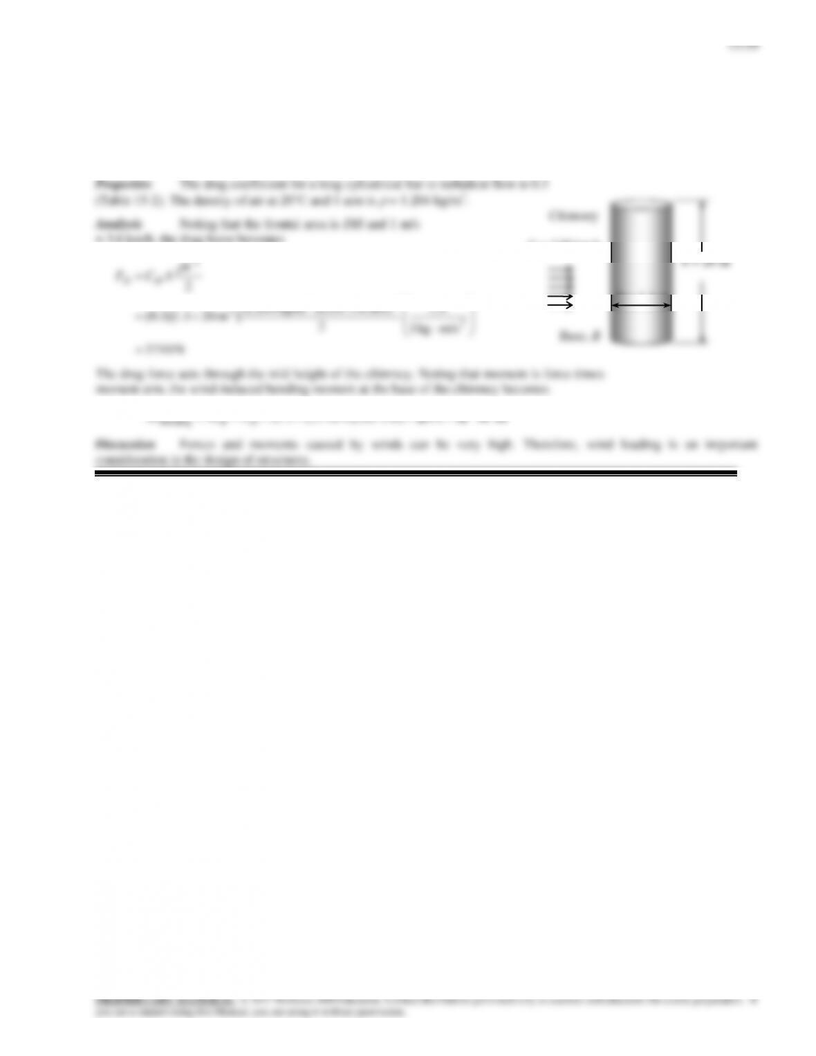
Solution The chimney of a factory is subjected to high winds. The bending moment at the base of the chimney is to
be determined.
Assumptions 1 The flow of air in the wind is steady, turbulent, and incompressible. 2 The ground effect on the wind and
the drag coefficient is negligible (a crude approximation) so that the resultant drag force acts through the center of the side
surface. 3 The edge effects are negligible and thus the chimney can be treated as a 2-D long cylinder.
= 3.6 km/h, the drag force becomes
N 1
)m/s 6.3/110)(kg/m 204.1(
2
23
2
2
V
ACF DD
h = 20 m
V = 110 km.h
D = 1.1 m
15–60
15–92E
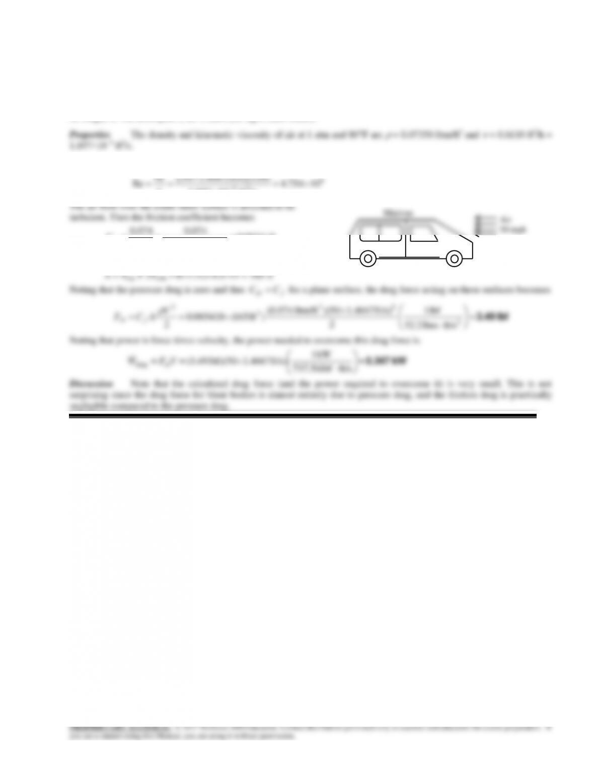
Solution The passenger compartment of a minivan is modeled as a rectangular box. The drag force acting on the top
and the two side surfaces and the power needed to overcome it are to be determined.
Assumptions 1 The air flow is steady and incompressible. 2 The air flow over the exterior surfaces is turbulent because of
constant agitation. 3 Air is an ideal gas. 4 The top and side surfaces of the minivan are flat and smooth (in reality they can
be rough). 5 The atmospheric air is calm (no significant winds).
Analysis The Reynolds number at the end of the top and side surfaces is
6
ft) ft/s](11 )4667.150[(
VL
15–93E
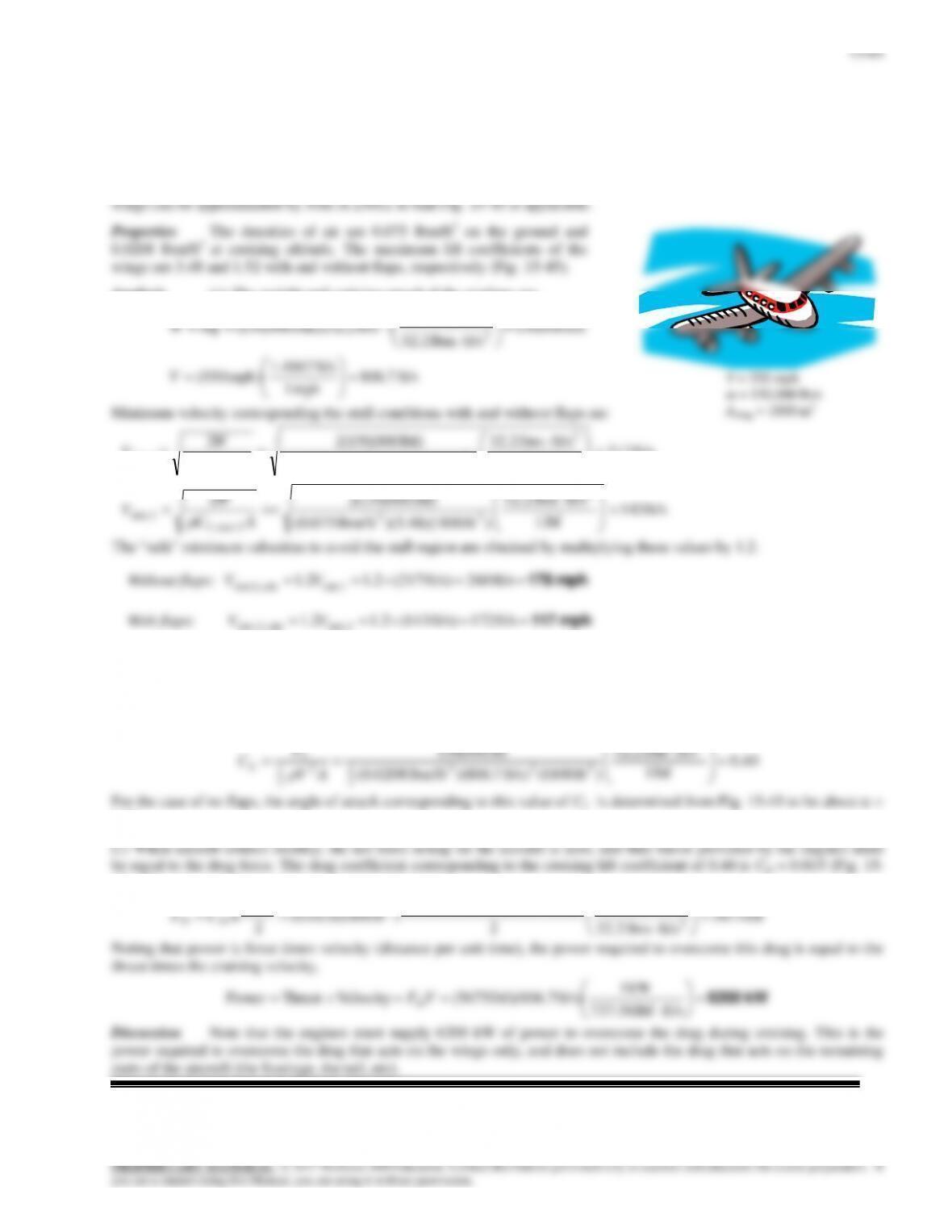
Solution Cruising conditions of a passenger plane are given. The minimum safe landing and takeoff speeds with and
without flaps, the angle of attack during cruising, and the power required are to be determined
Assumptions 1 The drag and lift produced by parts of the plane other than the wings are not considered. 2 The wings are
assumed to be two-dimensional airfoil sections, and the tip effects are neglected. 4 The lift and drag characteristics of the
Analysis (a) The weight and cruising speed of the airplane are
lbf 000,150
ft/slbm 32.2
lbf 1
)ft/s 2.32)(lbm 000,150( 2
2
mgW
ft/s 7.806
mph 1
ft/s 4667.1
)mph 550(
V
Minimum velocity corresponding the stall conditions with and without flaps are
ft/s 217
lbf 1
ft/slbm 32.2
)ft 1800)(52.1)(lbm/ft 075.0(
lbf) 000,150(2
22
23
1max,
1min
AC
W
V
L
ft/slbm 32.2
lbf) 000,150(2
22
W
since 1 mph = 1.4667 ft/s. Note that the use of flaps allows the plane to takeoff and land at considerably lower velocities,
and thus at a shorter runway.
(b) When an aircraft is cruising steadily at a constant altitude, the lift must be equal to the weight of the aircraft, FL = W.
Then the lift coefficient is determined to be
40.0
lbf 1
ft/slbm 2.32
)ft 1800(ft/s) 7.806)(lbm/ft 0208.0(
lbf 000,150 2
223
2
1
2
2
1
AV
F
CL
L
For the case of no flaps, the angle of attack corresponding to this value of CL is determined from Fig. 15-45 to be about =
3.5.
45). Then the drag force acting on the wings becomes
lbf 1
ft/s) 7.806)(lbm/ft 0208.0(
23
2
2
V = 550 mph
m = 150,000 lbm
Awing = 1800 m2
15–62
15–94
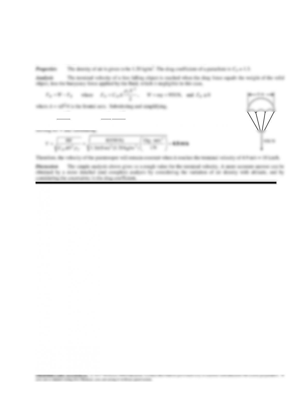
Solution The total weight of a paratrooper and its parachute is given. The terminal velocity of the paratrooper in air is
to be determined.
Assumptions 1 The air flow over the parachute is turbulent so that the tabulated value of the drag coefficient can be used.
2 The variation of the air properties with altitude is negligible. 3 The buoyancy force applied by air to the person (and the
parachute) is negligible because of the small volume occupied and the low air density.
W
V
D
CW
V
AC f
D
f
D 24
2
2
2
2
15–95
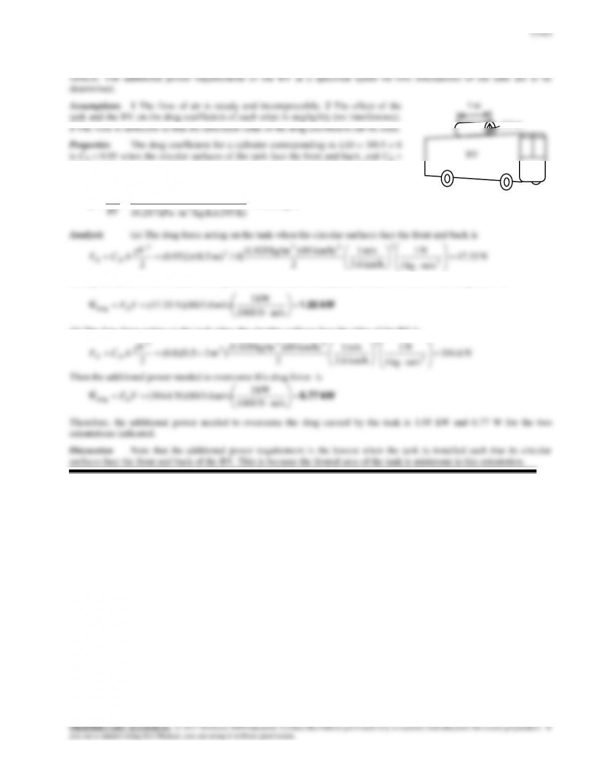
Solution The water needs of a recreational vehicle (RV) are to be met by installing a cylindrical tank on top of the
0.8 when the circular surfaces of the tank face the sides of the RV (Table 15-2). The
density of air at the specified conditions is
3
3kg/m 028.1
K) /kg.K)(295mkPa (0.287
kPa 87
RT
P
m/skg 1
km/h 6.3
2
22
Noting that power is force times velocity, the amount of additional power needed to overcome this drag force is
kW 1
(b) The drag force acting on the tank when the circular surfaces face the sides of the RV is
kW 1
N 1
m/s 1
km/h) 80)(kg/m 028.1(
2
23
2
2
15–64
15–96
Solution A smooth ball is moving at a specified velocity. The increase in the drag coefficient when the ball spins is
to be determined.
Assumptions 1 The outer surface of the ball is smooth. 2 The air is calm (no winds or
3500 rpm
15–65
15–97
Solution A fairing is installed to the front of a rig to reduce the drag coefficient. The maximum speed of the rig after
the fairing is installed is to be determined.
Assumptions 1 The rig moves steadily at a constant velocity on a straight path in calm weather. 2 The bearing friction
resistance is constant. 3 The effect of velocity on the drag and rolling resistance coefficients is negligible. 4 The buoyancy
N 5154
m/s kg1
N 1
2
m/s) 6.3/110)( kg/m25.1(
)m 2.9)(96.0(
22
23
2
2
1
1
V
ACF DD
2
2
2
222bearingRRdrag2bearingtotal 5154
2
350)( V
V
ACVFFFWWWW DRRD
Substituting the known quantities,
2
2
2
2
3
2N 5154
m/s kg1
N 1
2
) kg/m25.1(
)m 2.9)(76.0(N 350
kW1
m/sN 1000
kW)423( V
V
or,
3
22 37.45504 423,000 VV
15–98E
Solution We are to estimate how much money is wasted by driving with a tennis ball on a car antenna.
15–99
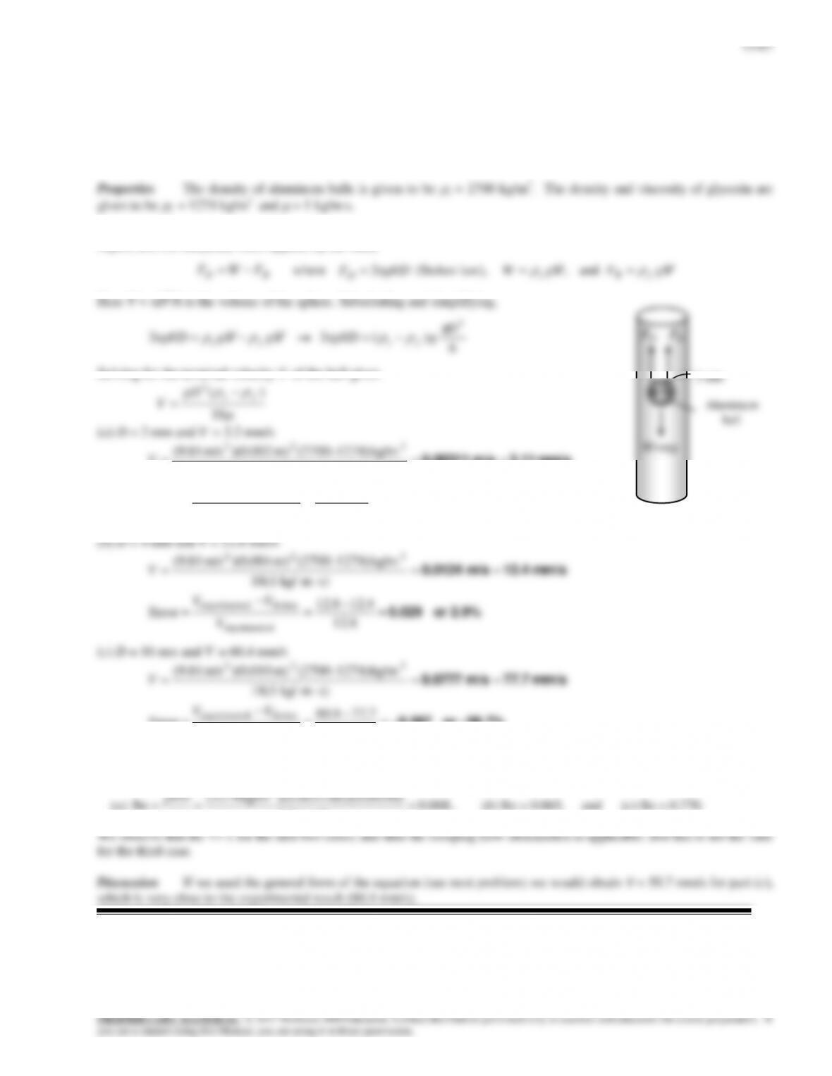
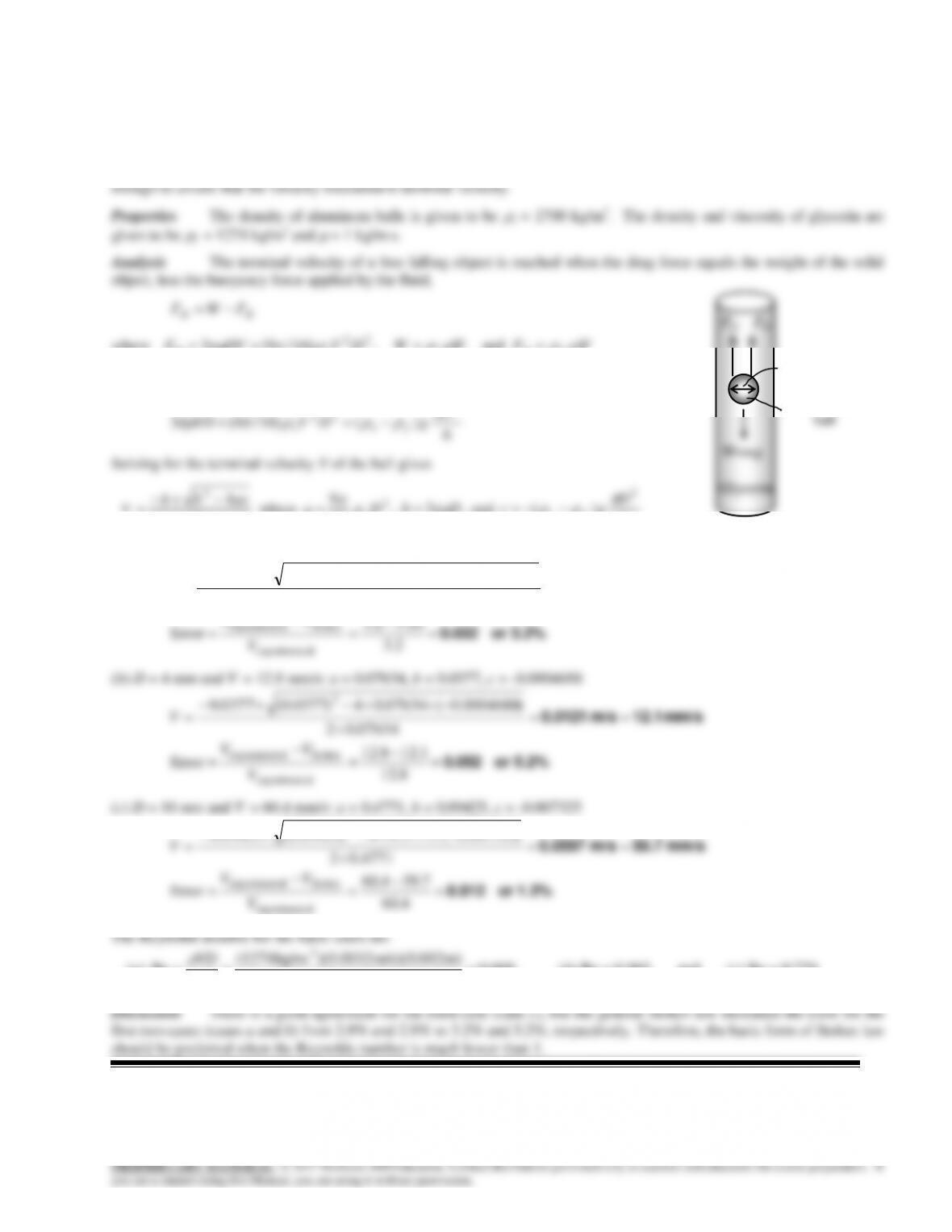
Solution Spherical aluminum balls are dropped into glycerin, and their terminal velocities are measured. The
velocities are to be compared to those predicted by Stokes law, and the error involved is to be determined.
Assumptions 1 The Reynolds number is low (at the order of 1) so that Stokes law is applicable (to be verified). 2 The
diameter of the tube that contains the fluid is large enough to simulate free fall in an unbounded fluid body. 3 The tube is
long enough to assure that the velocity measured is terminal velocity.
Analysis The terminal velocity of a free falling object is reached when the drag force equals the weight of the solid
object, less the buoyancy force applied by the fluid,
BD FWF
where
VDFD
3
(Stokes law),
VV
gFgW f
Bs
and ,
Here V = D3/6 is the volume of the sphere. Substituting and simplifying,
6
)(3 3
3
D
gVDggVD f
s
f
s
VV
Solving for the terminal velocity V of the ball gives
)(
2
f
s
gD
mm/s 3.11m/s 0.00311
s)m kg/ 18(1
kg/m1274)–(2700m) 002.0)(m/s 81.9( 322
V
2.9% or 0.029
2.3
11.32.3
Error
alexperiment
Stokesalexperiment
V
VV
28.7%– or 0.287
4.60
7.774.60
Error
alexperiment
Stokesalexperiment
V
VV
There is a good agreement for the first two diameters. However the error for third one is large. The Reynolds number for
each case is
(a)
008.0
m/s kg1
m) m/s)(0.002 )(0.0032 kg/m(1274
Re
3
VD
, (b) Re = 0.065, and (c) Re = 0.770.
W=mg
3 mm
Glycerin
FD FB
15–68
15-100
Solution Spherical aluminum balls are dropped into glycerin, and their terminal velocities are measured. The
velocities predicted by a more general form of Stokes law and the error involved are to be determined.
Assumptions 1 The Reynolds number is low (of order 1) so that Stokes law is applicable (to be verified). 2 The diameter
of the tube that contains the fluid is large enough to simulate free fall in an unbounded fluid body. 3 The tube is long
where
22
)16/9(3 DVDVFsD
,
VV
gFgW f
Bs
and ,
Here
V
= D3/6 is the volume of the sphere. Substituting and simplifying,
3
22 D
3 mm
Aluminum
FD FB
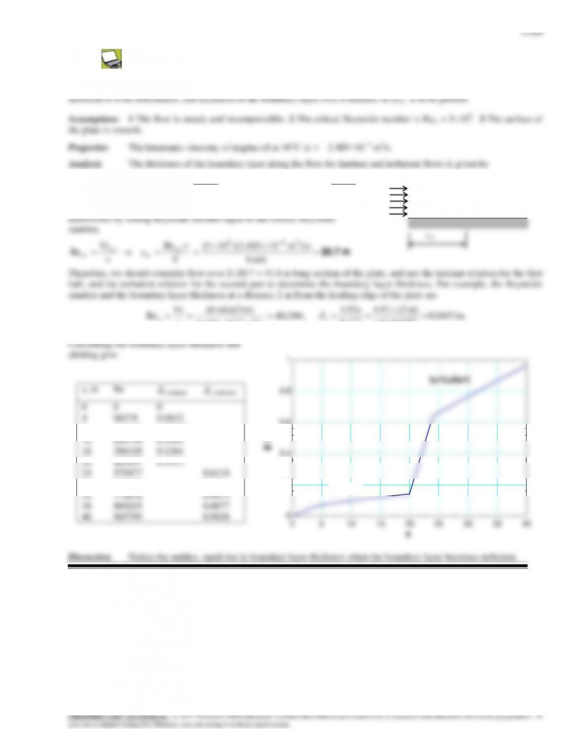
15-101
Solution Engine oil flows over a long flat plate. The distance from the leading edge xcr where the flow becomes
Laminar flow:
2/1
Re
91.4
x
x
x
, Turbulent flow:
5/1
Re
38.0
x
x
x
The distance from the leading edge xcr where the flow turns turbulent is
V
15–70
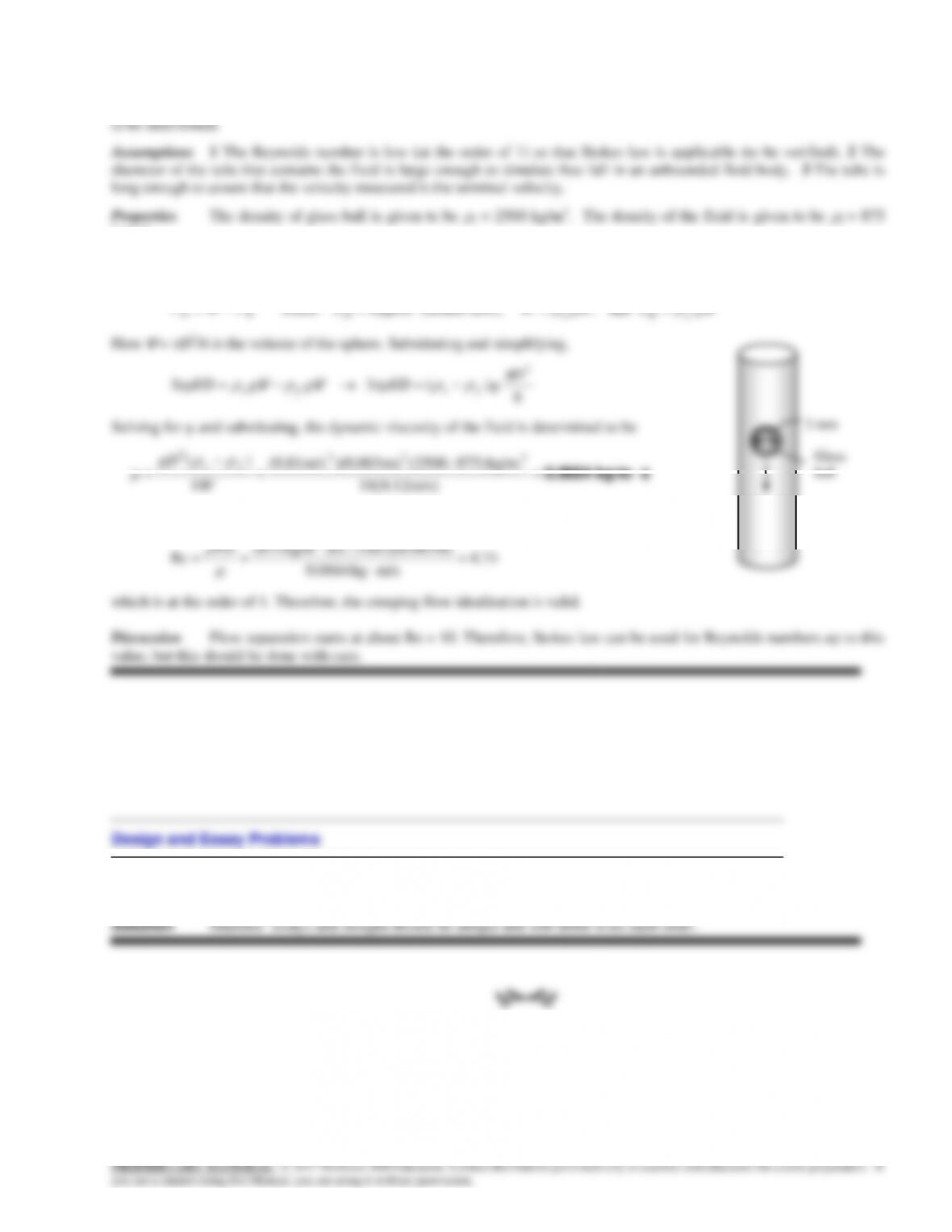
15-102
Solution A spherical object is dropped into a fluid, and its terminal velocity is measured. The viscosity of the fluid is
kg/m3.
Analysis The terminal velocity of a free falling object is reached when the drag force equals the weight of the solid
object, less the buoyancy force applied by the fluid,
18
V
The Reynolds number is
74.4
m/skg 0.0664
m) m/s)(0.003 )(0.12kg/m (875
Re
3
VD
which is at the order of 1. Therefore, the creeping flow idealization is valid.
Discussion Flow separation starts at about Re = 10. Therefore, Stokes law can be used for Reynolds numbers up to this
value, but this should be done with care.
Design and Essay Problems
15–103 to 15–105
0.12 m/s