14–99E
Solution The velocity profile in fully developed laminar flow in a circular pipe is given. The volume flow rate, the
pressure drop, and the useful pumping power required to overcome this pressure drop are to be determined.
1.03910-3 lbm/fts, respectively.
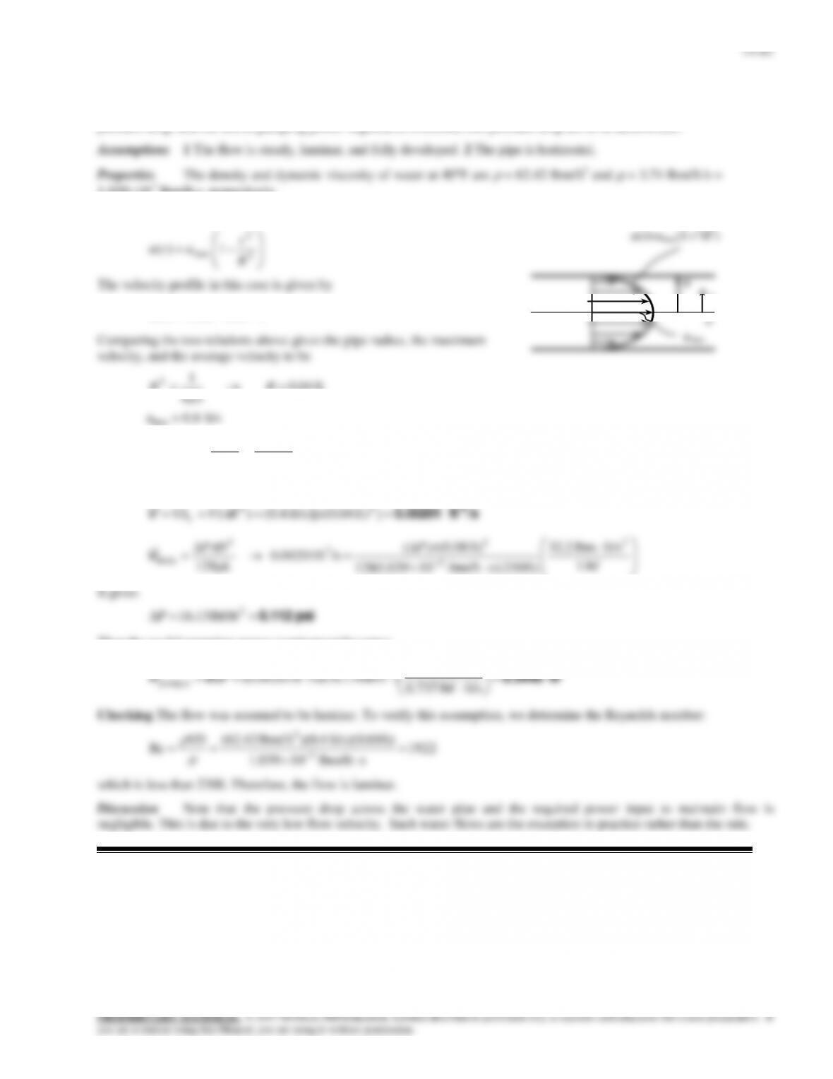
Analysis The velocity profile in fully developed laminar flow in a circular pipe is
2
2
max 1)( R
r
uru
The velocity profile in this case is given by
)6251(8.0)( 2
rru
ft 04.0
625
1
2 RR
ft/s 4.0
2
ft/s 0.8
2
max u
VV avg
Then the volume flow rate and the pressure drop become
/sft 0.00201
3
]ft) (0.04ft/s)[ 4.0()(
22
RVVA
c
V
lbf 1
ft/slbm 2.32
ft) s)(250lbm/ft 10039.1(128
ft) (0.08)(
/sft 0.00201
128
2
3
4
3
4
horiz
P
L
DP
V
It gives
psi 0.112 2
lbf/ft 13.16P
Then the useful pumping power requirement becomes
W1
R
r
0
umax
u(r)=umax(1-r2/R2)
14–82
14-100E
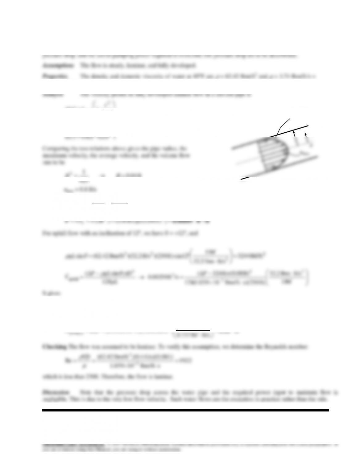
Solution The velocity profile in fully developed laminar flow in a circular pipe is given. The volume flow rate, the
1.03910-3 lbm/fts, respectively.
2
2
max 1)( R
r
uru
The velocity profile in this case is given by
)6251(8.0)( 2
rru
Comparing the two relations above gives the pipe radius, the
maximum velocity, the average velocity, and the volume flow
rate to be
ft 04.0
625
1
2 RR
ft/s 4.0
2
ft/s 0.8
2
max u
VV avg
3
22
psi 64.22lbf/ft 3260 2P
Then the useful pumping power requirement becomes
W1
R
r
0
umax
u(r) = umax(1-r2/R2)
14-101
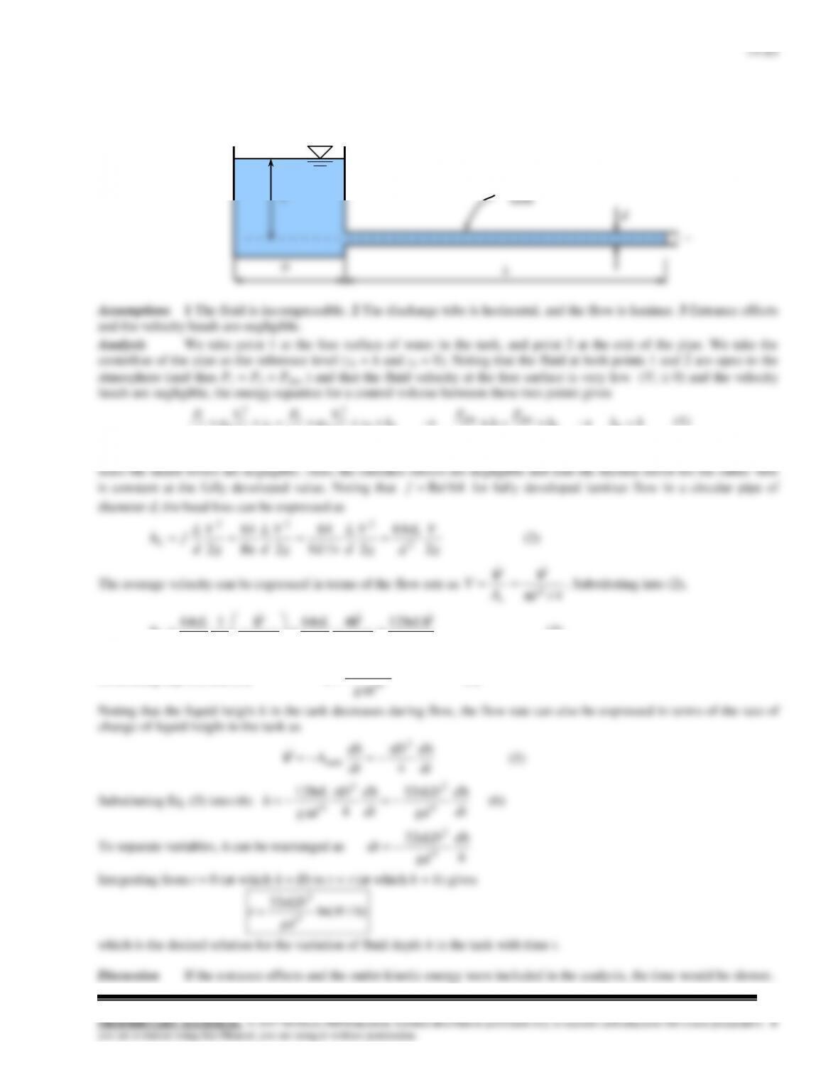
Solution A highly viscous liquid discharges from a large container through a small diameter tube in laminar flow. A
relation is to be obtained for the variation of fluid depth in the tank with time.
hhh
g
P
h
g
P
hz
g
V
g
P
z
g
V
g
P
LL
atmatm
L
22 2
2
2
2
2
1
2
1
1
1
(1)
where h is the liquid height in the tank at any time t. The total head loss through the pipe consists of major losses in the pipe
4/
2
d
A
c
42222
128
2
464
4/
2
164
dg
L
dgd
L
d
g
d
L
hL
VVV
(3)
Combining Eqs. (1) and (3):
4
128
dg
L
h
V
(4)
Discharge
14–84
14-102
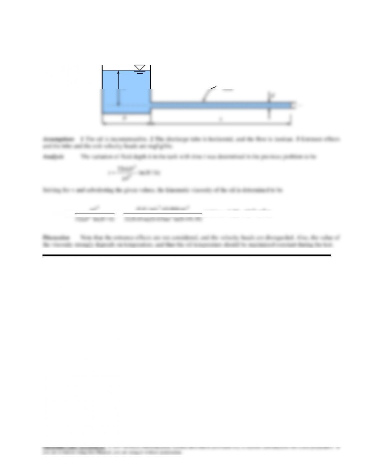
Solution Using the setup described in the previous problem, the viscosity of an oil is to be determined for a given set
of data.
/sm 101.33 25–
s) 1400(
4)ln(0.4/0.3m) m)(0.63 32(0.65
m) 006.0)(m/s 81.9(
)/ln(32 2
42
2
4
t
hHLD
gd
Discharge
tube
h
d
14-103
14–86
14-104
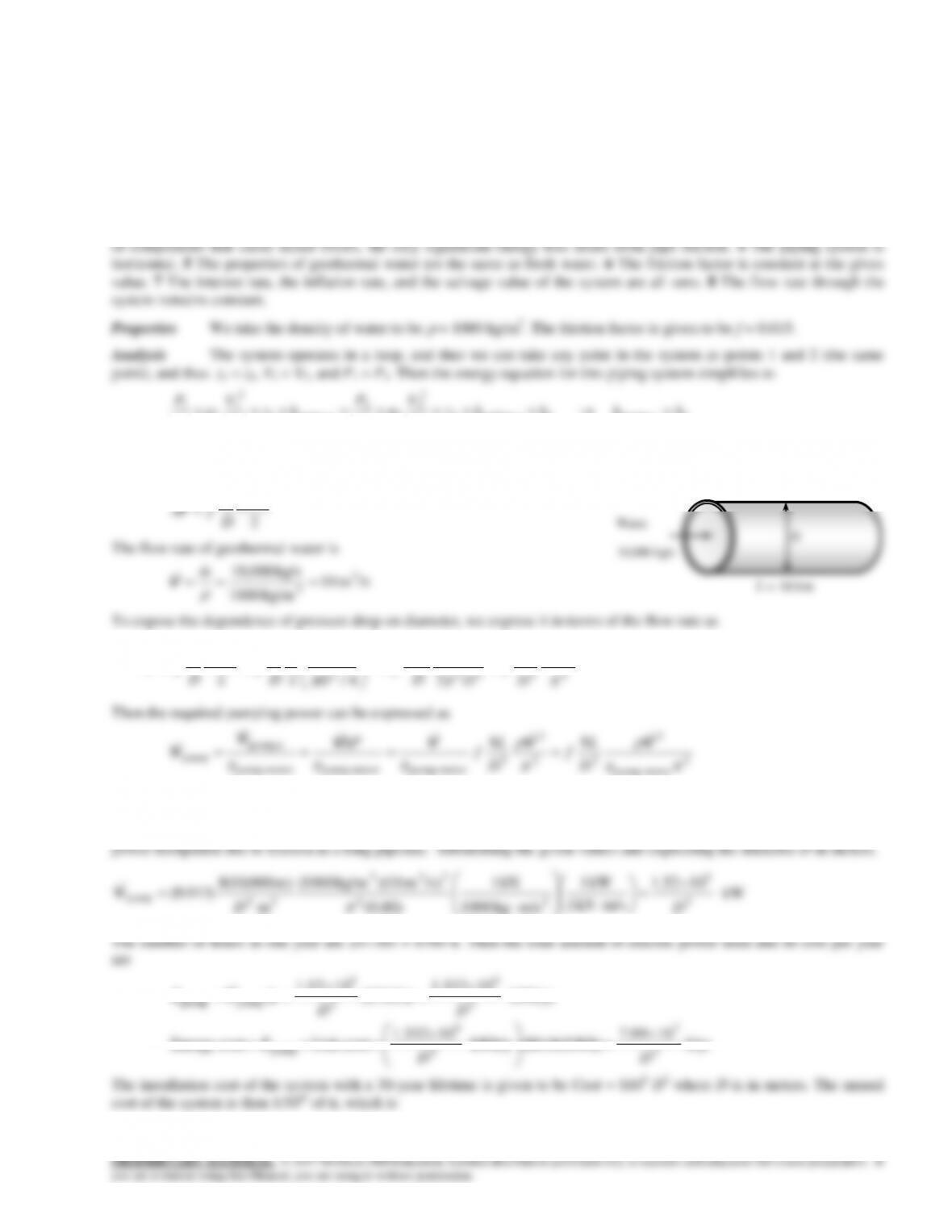
Solution The piping system of a geothermal district heating system is being designed. The pipe diameter that will
optimize the initial system cost and the energy cost is to be determined.
Assumptions 1 The flow is steady and incompressible. 2 The entrance effects are negligible, and thus the flow is fully
developed. 3 The minor losses are negligible because of the large length–to-diameter ratio and the relatively small number
22 up ump,e turbine,2
2
2
1
2
up ump,1
2
1
1
1
LL hhhhz
g
V
g
P
hz
g
V
g
P
That is, the pumping power is to be used to overcome the head losses due to friction in flow. When the minor losses are
disregarded, the head loss for fully developed flow in a pipe of length L and diameter D can be expressed as
2
2
V
D
L
fP
The flow rate of geothermal water is
/sm 10
kg/m1000
kg/s10,000 3
3
m
V
To expose the dependence of pressure drop on diameter, we express it in terms of the flow rate as
2
2
542
2
2
2
28
2
16
4/
22
VV
V
D
L
f
D
D
L
f
D
D
L
f
V
D
L
fP
2
motor–pump
52
5
motor–pumpmotor–pumpmotor–pump
D
D
Note that the pumping power requirement is proportional to f and L, consistent with our intuitive expectation. Perhaps not
so obvious is that power is proportional to the cube of flow rate. The fact that the power is inversely proportional to pipe
diameter D to the fifth power averages that a slight increase in pipe diameter will manifest as a tremendous reduction in
L = 10 km
D
Water
10,000 kg/s
14–87
year)(per 10$3.33
yr 30
$10
timeLife
cost Total
cost System 24
26
D
D
Then the total annual cost of the system (installation + operating) becomes
Total cost = Energy cost + System cost =
$/yr 103.33
107.99 24
5
7
D
D
D = 3.5 m
This is the optimum pipe diameter that minimizes the total cost of the system under stated assumptions. A larger
diameter pipe will increase the system cost more than it decreases the energy cost, and a smaller diameter pipe will increase
the system cost more than it decreases the energy cost.
14-105
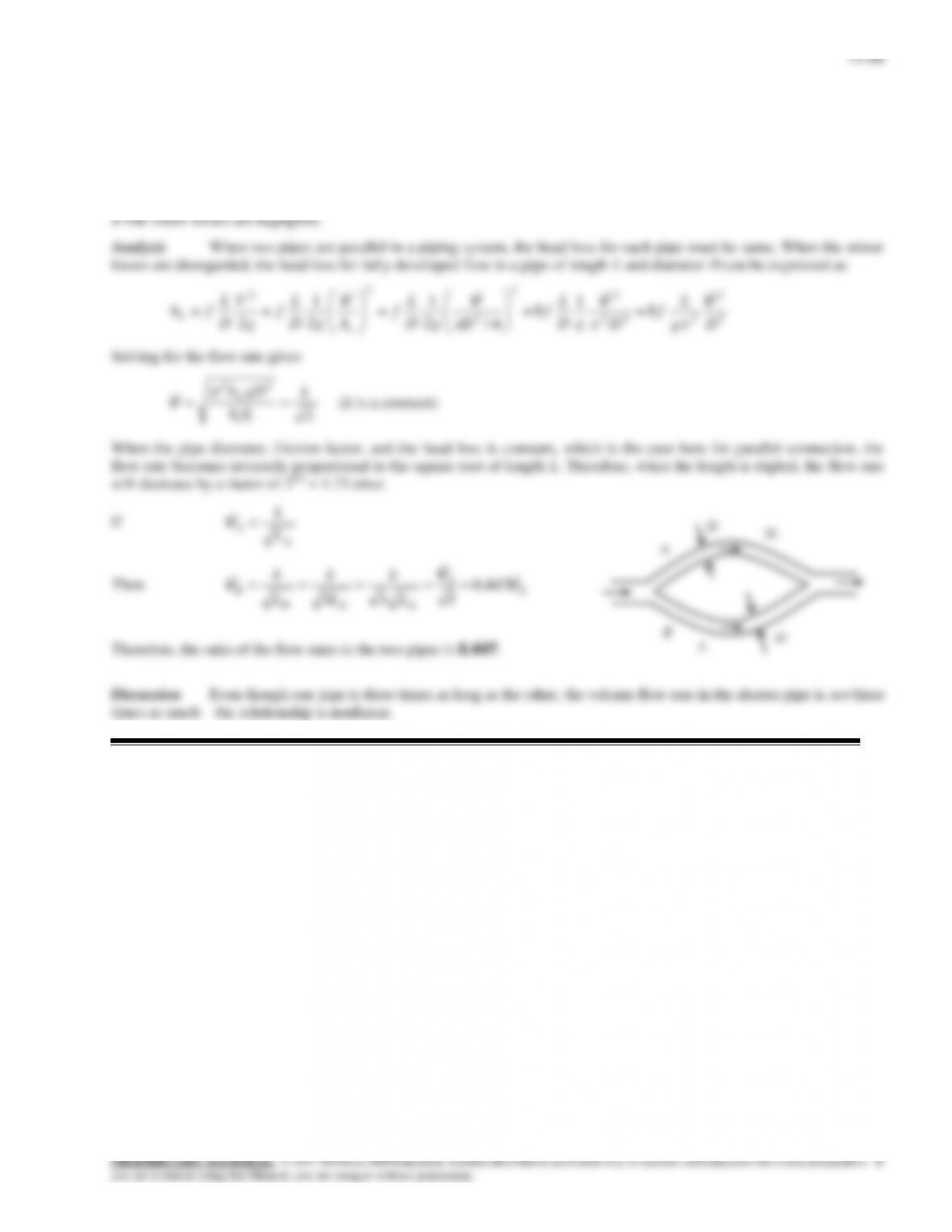
Solution Two pipes of identical diameter and material are connected in parallel. The length of one of the pipes is
three times the length of the other. The ratio of the flow rates in the two pipes is to be determined.
Assumptions 1 The flow is steady and incompressible. 2 The flow is fully turbulent in both pipes and thus the friction
factor is independent of the Reynolds number (it is the same for both pipes since they have the same material and diameter).
14–89
14-106
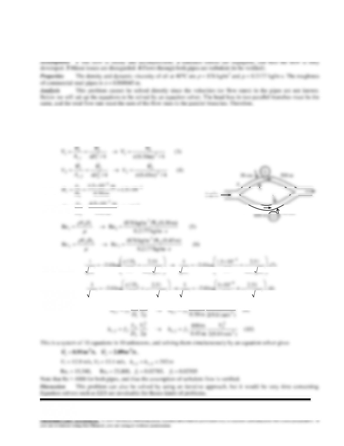
Solution A pipeline that transports oil at a specified rate branches out into two parallel pipes made of commercial
steel that reconnects downstream. The flow rates through each of the parallel pipes are to be determined.
(1) 2,1, LL hh
(2) 3 2121
VVVVV
We designate the 30-cm diameter pipe by 1 and the 45-cm diameter pipe by 2. The average velocity, the relative roughness,
the Reynolds number, friction factor, and the head loss in each pipe are expressed as
(4)
4/m)45.0(
4/
(3)
4/m)30.0(
4/
2
2
2
2
2
2
2,
2
2
2
1
1
2
1
1
1,
1
1
VVV
VVV
V
D
A
V
V
D
A
V
c
c
800 m
45 cm
105.1
m 30.0
m 105.4
rf
4
5
1
1
1
D
(6)
kg/m2177.0
m) (0.45) kg/m876(
Re Re
2
3
2
22
2
s
DV
V
Re
51.2
7.3
105.1
log0.2
1
Re
51.2
7.3
/
log0.2
1
11
4
111
1
1
fff
D
f
(7)
Re
51.2
7.3
101
log0.2
1
Re
51.2
7.3
/
log0.2
1
22
4
222
2
2
fff
D
f
(8)
(9)
)m/s 81.9(2
m 30.0
m 500
22
2
1
11,
2
1
1
1
11,
V
fh
g
V
D
L
fh LL
(10)
)m/s 81.9(2
m 45.0
m 800
22
2
2
22,
2
2
2
2
22,
V
fh
g
V
D
L
fh LL
This is a system of 10 equations in 10 unknowns, and solving them simultaneously by an equation solver gives
/sm 2.09/sm 0.91 33 21 ,
VV
,
V1 = 12.9 m/s, V2 = 13.1 m/s,
m 392 2,1, LL hh
Re1 = 15,540, Re2 = 23,800, f1 = 0.02785, f2 = 0.02505
Note that Re > 4000 for both pipes, and thus the assumption of turbulent flow is verified.
Discussion This problem can also be solved by using an iterative approach, but it would be very time consuming.
Equation solvers such as EES are invaluable for theses kinds of problems.
30 cm
500 m
A
3 m3/s
1
14-107
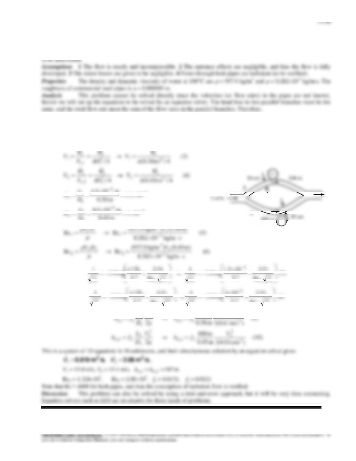
Solution The piping of a district heating system that transports hot water at a specified rate branches out into two
parallel pipes made of commercial steel that reconnects downstream. The flow rates through each of the parallel pipes are
(1) 2,1, LL hh
(2) 3 2121
VVVVV
We designate the 30-cm diameter pipe by 1 and the 45-cm diameter pipe by 2. The average velocity, the relative roughness,
the Reynolds number, friction factor, and the head loss in each pipe are expressed as
(4)
4/m)45.0(
4/
(3)
4/m)30.0(
4/
2
2
2
2
2
2
2,
2
2
2
1
1
2
1
1
1,
1
1
VVV
VVV
V
D
A
V
V
D
A
V
c
c
800 m
45 cm
105.1
m 30.0
m 105.4
rf
4
5
1
1
1
D
30 cm
500 m
A
3 m3/s
1

14–91
14-108E
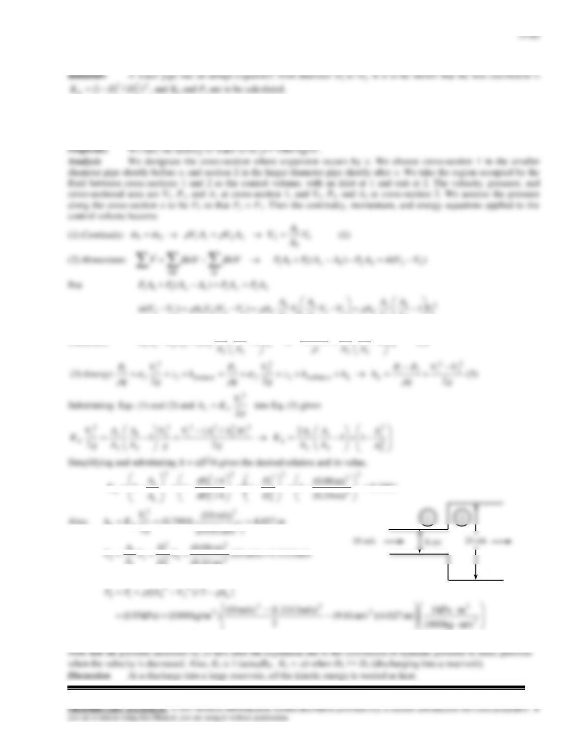
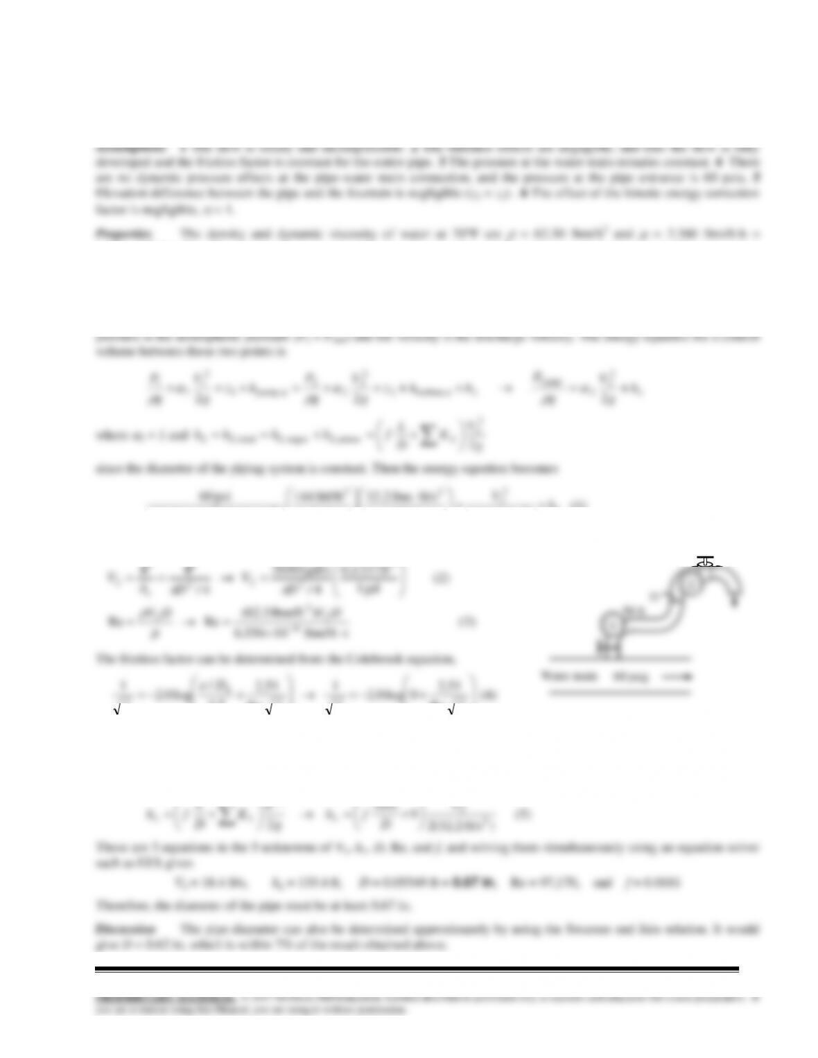
Solution A water fountain is to be installed at a remote location by attaching a cast iron pipe directly to a water main.
For a specified flow rate, the minimum diameter of the piping system is to be determined.
Assumptions 1 The flow is steady and incompressible. 2 The entrance effects are negligible, and thus the flow is fully
developed and the friction factor is constant for the entire pipe. 3 The pressure at the water main remains constant. 4 There
are no dynamic pressure effects at the pipe-water main connection, and the pressure at the pipe entrance is 60 psia. 5
Elevation difference between the pipe and the fountain is negligible (z2 = z1) . 6 The effect of the kinetic energy correction
factor is negligible,
= 1.
valve.
Analysis We choose point 1 in the water main near the entrance where the pressure is 60 psig and the velocity in the
pipe to be low. We also take point 1 as the reference level. We take point 2 at the exit of the water fountain where the
L
h
V
)ft/s 2.32(2
lbf 1
ft/slbm 32.2
psi1
lbf/ft 144
)ft/s 2.32)(lbm/ft 3.62(
psi60
2
2
2
22
23
(1)
The average velocity in the pipe and the Reynolds number are
1
(2)
gal 1
ft 0.1337
4/
gal/s 15/60
4/
3
2
2
2
2
D
V
D
A
V
c
VV
f
D
ff
D
f
h
Re
51.2
7.3
/00085.0
log0.2
1
Re
51.2
7.3
/
log0.2
1
(4)
952.01.135.03 valveangle, valvegate,elbow,entrance,
LLLLL KKKKK
Then the total head loss becomes
(5)
)ft/s 2.32(2
9
ft 70
22
2
2
2V
D
fh
g
V
K
D
L
fh LLL
These are 5 equations in the 5 unknowns of V2, hL, D, Re, and f, and solving them simultaneously using an equation solver
such as EES gives
V2 = 12.1 ft/s, hL = 136.4 ft, D = 0.0594 ft = 0.713 in, Re = 68,080, and f = 0.04365
Therefore, the diameter of the pipe must be at least 0.713 in.
Discussion The pipe diameter can also be determined approximately by using the Swamee and Jain relation.
D
70 ft
2
14–92
14-109E
Solution A water fountain is to be installed at a remote location by attaching a cast iron pipe directly to a water main.
For a specified flow rate, the minimum diameter of the piping system is to be determined.
6.55610-4 lbm/fts. The plastic pipes are considered to be smooth, and thus their roughness is
= 0. The minor loss
coefficient is KL = 0.5 for a sharp-edged entrance, KL = 1.1 for a 90 miter bend without vanes, KL = 0.2 for a fully open
gate valve, and KL = 5 for an angle valve.
Analysis We choose point 1 in the water main near the entrance where the pressure is 60 psig and the velocity in the
pipe to be low. We also take point 1 as the reference level. We take point 2 at the exit of the water fountain where the
L
h
V
)ft/s 2.32(2
lbf 1
ft/slbm 32.2
psi1
lbf/ft 144
)ft/s 2.32)(lbm/ft 3.62(
psi60
2
2
2
22
23
(1)
The average velocity in the pipe and the Reynolds number are
1
(2)
gal 1
ft 0.1337
4/
gal/s 20/60
4/
3
2
2
2
2
D
V
D
A
V
c
VV
f
Re
Re
7.3
The sum of the loss coefficients is
952.01.135.03 valveangle, valvegate,elbow,entrance,
LLLLL KKKKK
Then the total head loss becomes
(5)
)ft/s 2.32(2
9
ft 50
22
2
2
2V
D
fh
g
V
K
D
L
fh LLL
These are 5 equations in the 5 unknowns of V2, hL, D, Re, and f, and solving them simultaneously using an equation solver
such as EES gives
V2 = 18.4 ft/s, hL = 133.4 ft, D = 0.05549 ft = 0.67 in, Re = 97,170, and f = 0.0181
Therefore, the diameter of the pipe must be at least 0.67 in.
Discussion The pipe diameter can also be determined approximately by using the Swamee and Jain relation. It would
give D = 0.62 in, which is within 7% of the result obtained above.
2