14–81
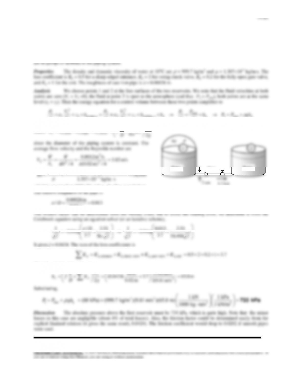
Solution The flow rate through a piping system connecting two water reservoirs with the same water level is given.
The absolute pressure in the pressurized reservoir is to be determined.
Assumptions 1 The flow is steady and incompressible. 2 The entrance effects are negligible, and thus the flow is fully
developed. 3 The flow is turbulent so that the tabulated value of the loss coefficients can be used (to be verified). 4 There
14–62
14–82
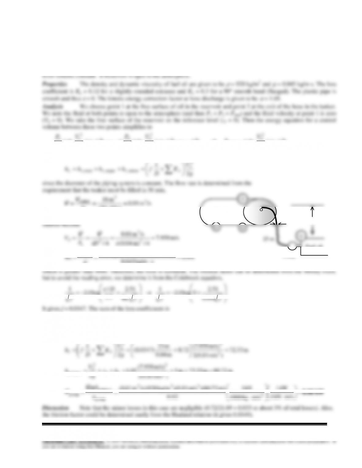
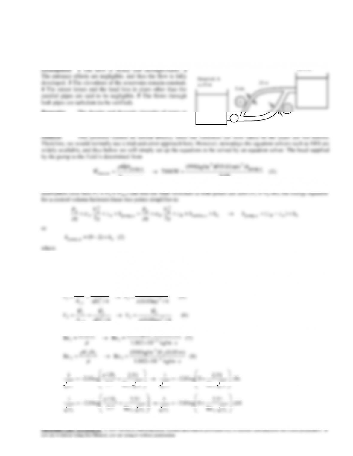
Solution A tanker is to be filled with fuel oil from an underground reservoir using a plastic hose. The required power
input to the pump is to be determined.
Assumptions 1 The flow is steady and incompressible. 2 The entrance effects are negligible, and thus the flow is fully
developed. 3 The flow is turbulent so that the tabulated value of the loss coefficients can be used (to be verified). 4 Fuel oil
LL hz
g
V
hhhz
g
V
g
P
hz
g
V
g
P 2
2
2
2 upump,e turbine,2
2
2
2
2
upump,1
2
1
1
1
2
2
2
where
g
V
K
D
L
fhhhh LLLLL 2
2
2
minor,major,total,
since the diameter of the piping system is constant. The flow rate is determined from the
requirement that the tanker must be filled in 30 min,
/sm 01.0
s) 6030(
m 18 3
3
tanker
t
V
V
Then the average velocity in the pipe and the Reynolds
Fuel oil
1
5 m
4 cm
Tanker
18 m3
2
14–83
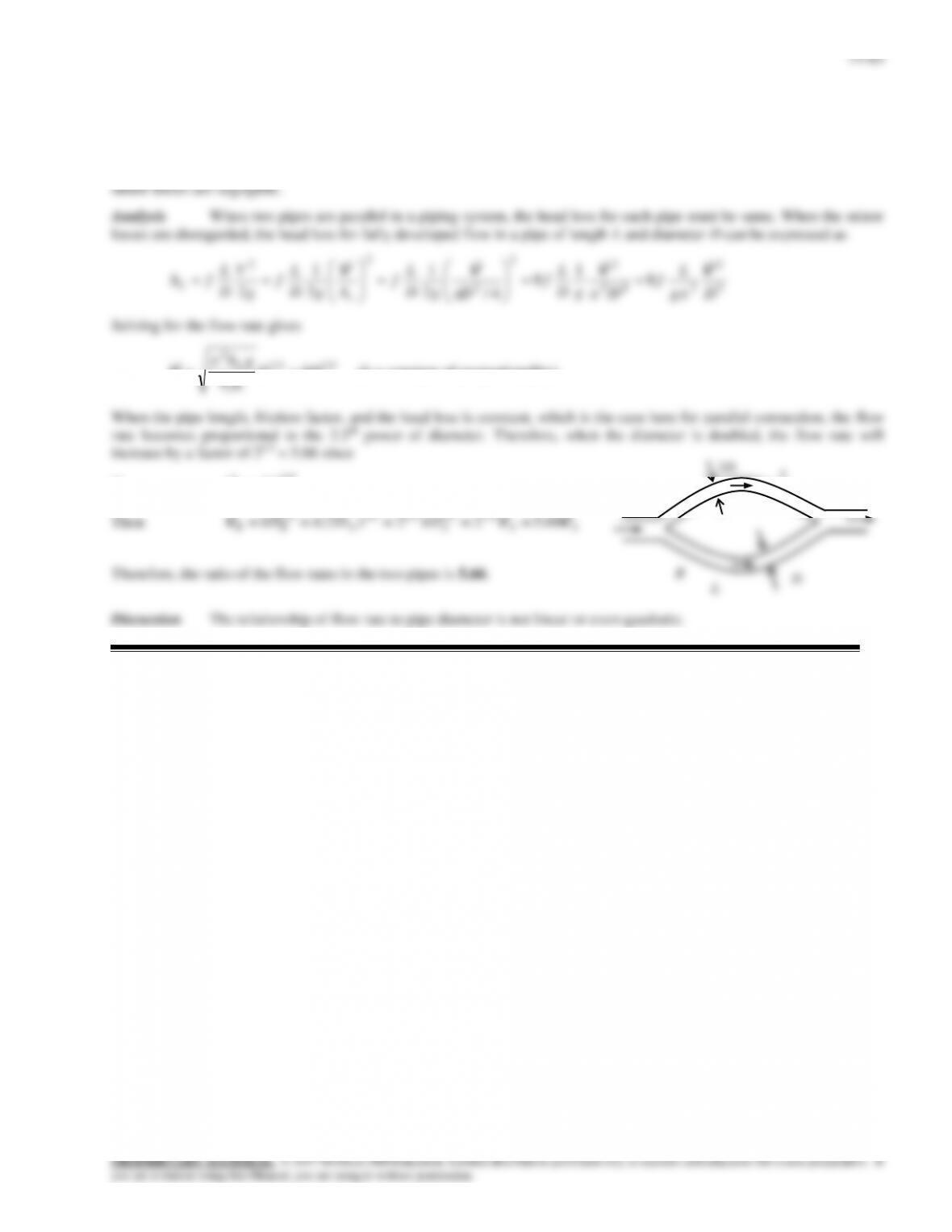
Solution Two pipes of identical length and material are connected in parallel. The diameter of one of the pipes is
twice the diameter of the other. The ratio of the flow rates in the two pipes is to be determined
Assumptions 1 The flow is steady and incompressible. 2 The friction factor is given to be the same for both pipes. 3 The
14–64
14–84
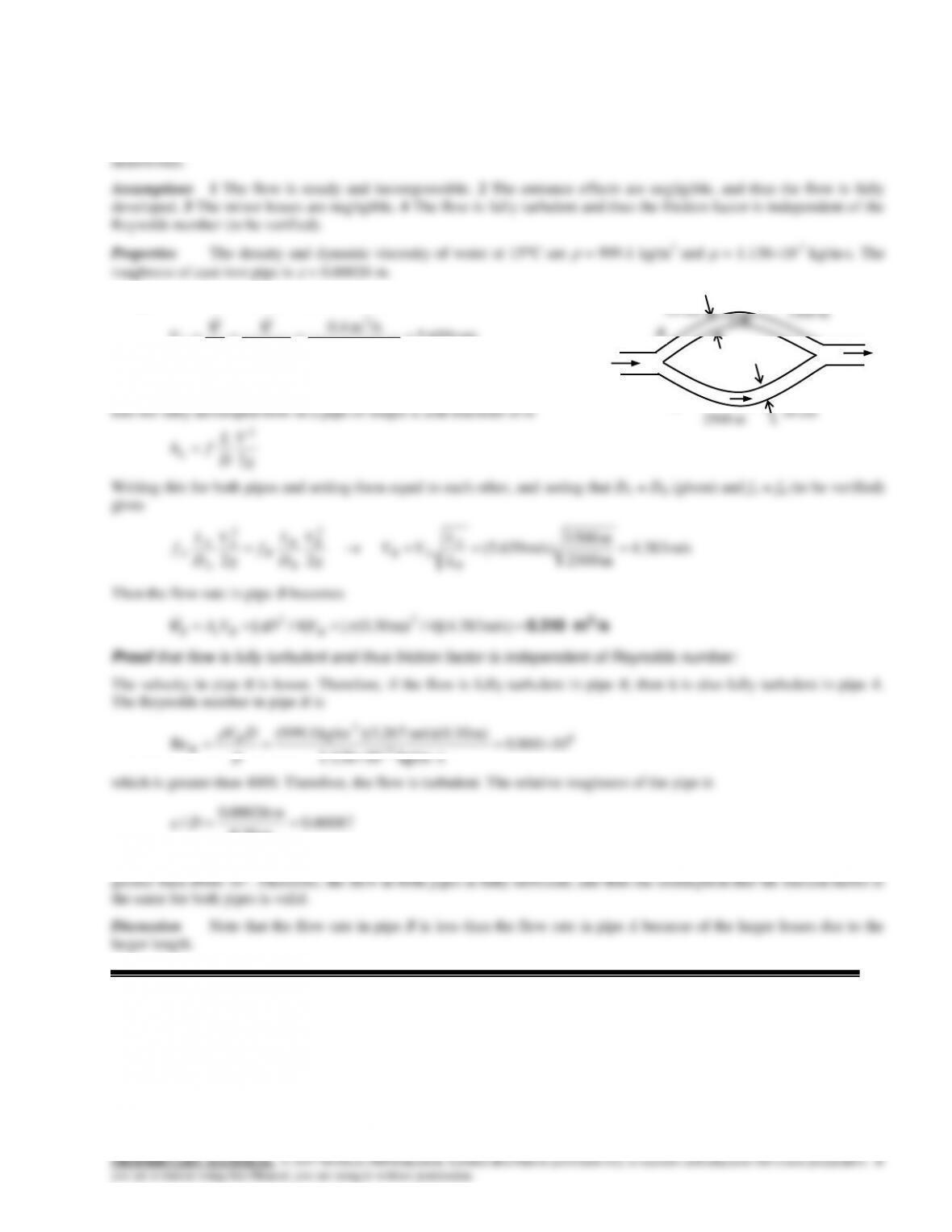
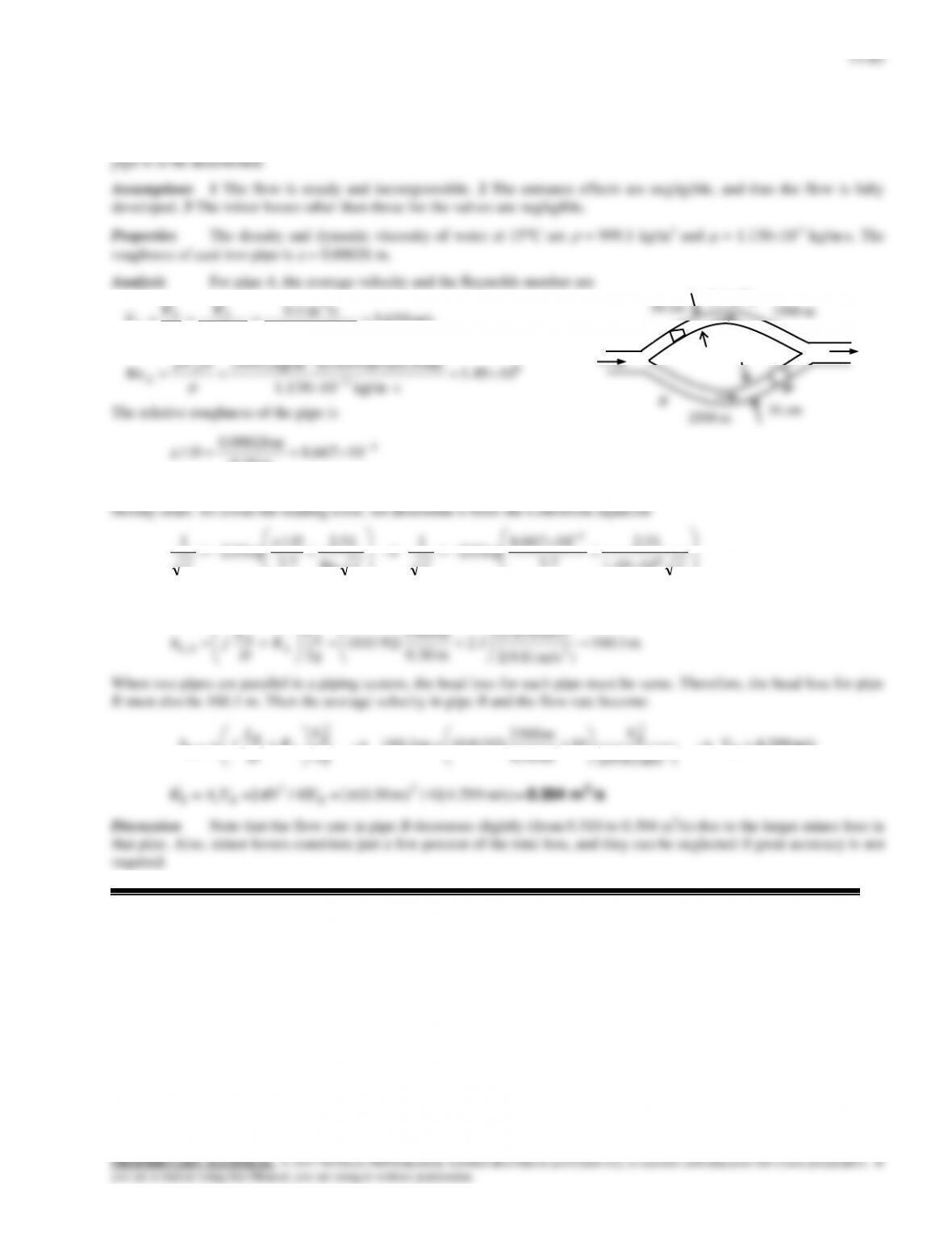
Solution Cast iron piping of a water distribution system involves a parallel section with identical diameters but
different lengths. The flow rate through one of the pipes is given, and the flow rate through the other pipe is to be
Analysis The average velocity in pipe A is
m/s 659.5
4/m) 30.0(
/sm 0.4
4/ 2
3
2
D
A
V
c
A
VV
When two pipes are parallel in a piping system, the head loss for each
pipe must be same. When the minor losses are disregarded, the head
2500 m
30 cm
30 cm
1500 m
A
B
0.4 m3/s
14–85
Solution Cast iron piping of a water distribution system involves a parallel section with identical diameters but
different lengths and different valves. The flow rate through one of the pipes is given, and the flow rate through the other
m/s 659.5
4/m) 30.0(
/sm 0.4
4/ 2
3
2
D
A
VA
c
A
A
VV
2500 m
6
3
m) m/s)(0.30 659.5)( kg/m1.999(
DVA
30 cm
1500 m
A
0.4 m3/s
14–66
14–86
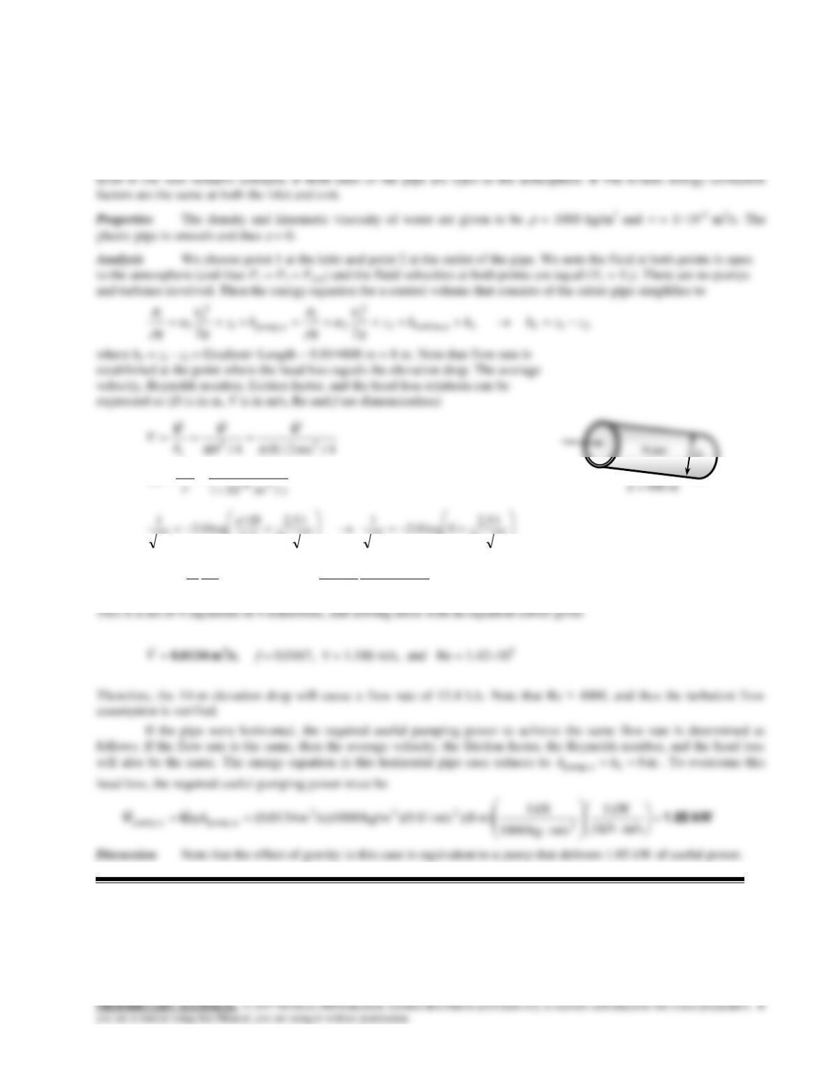
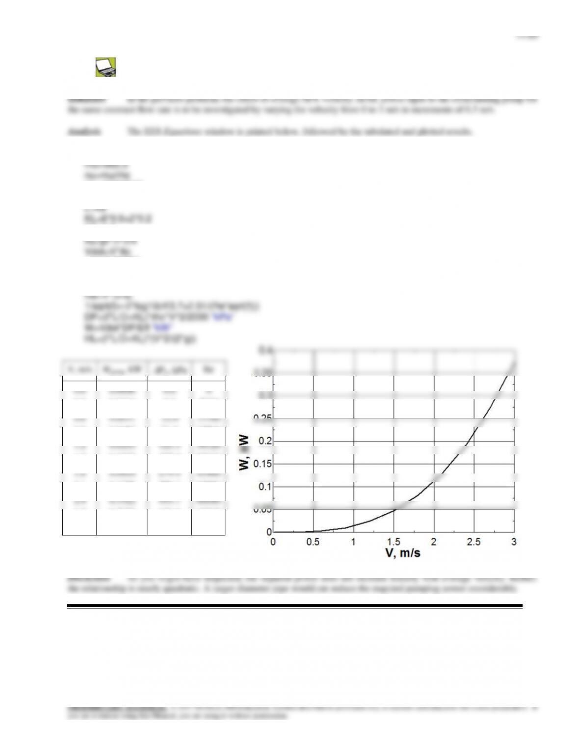
Solution Water is transported through a plastic pipe by gravity. The flow rate of water and the power requirement to
maintain this flow rate if the pipe were horizontal are to be determined.
Assumptions 1 The flow is steady and incompressible. 2 The entrance effects are negligible, and thus the flow is fully
developed. 3 The pipe involves no components such as bends, valves, and connectors, and thus no minor losses. 4 Water
14–87
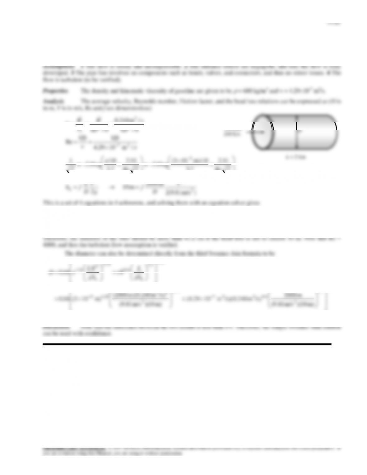
Solution The flow rate and the maximum head loss in a gasoline pipeline are given. The required minimum diameter
of the pipe is to be determined.
14–68
14–88
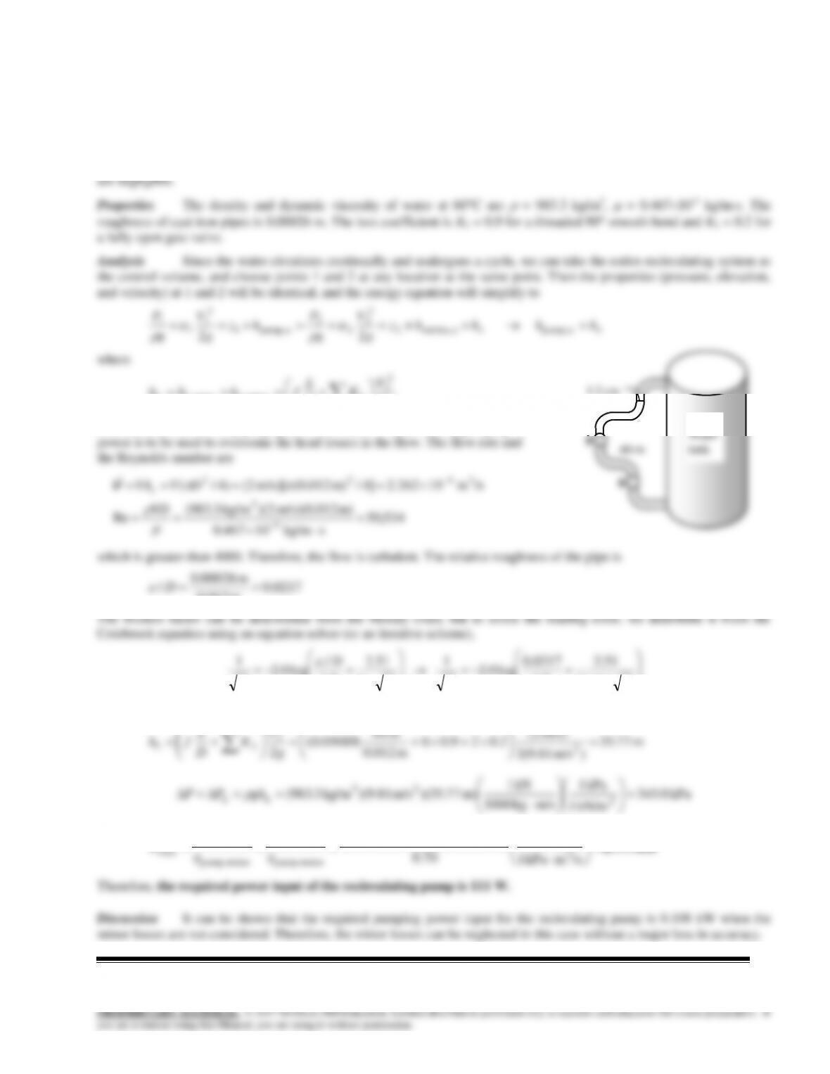
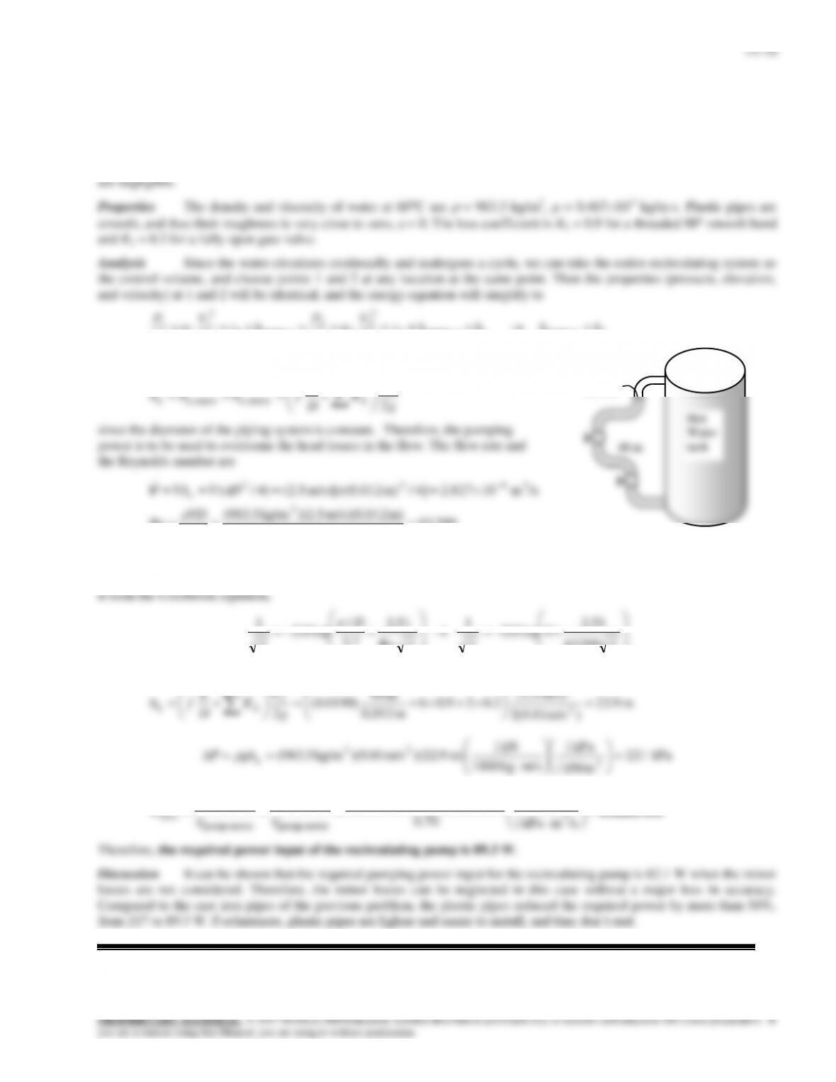
Solution Hot water in a water tank is circulated through a loop made of cast iron pipes at a specified average
velocity. The required power input for the recirculating pump is to be determined.
Assumptions 1 The flow is steady and incompressible. 2 The flow is fully developed. 3 The flow is turbulent so that the
tabulated value of the loss coefficients can be used (to be verified). 4 Minor losses other than those for elbows and valves
g
V
K
D
L
fhhh LLLL 2
2
2
minor,major,
since the diameter of the piping system is constant. Therefore, the pumping
1.2 cm
Hot
Water
14–89
g=9.81
mu=0.000467
D=0.012
Eff=0.7
eps=0.00026
rf=eps/D
“Reynolds number”
14–90
Solution Hot water in a water tank is circulated through a loop made of plastic pipes at a specified average velocity.
The required power input for the recirculating pump is to be determined.
Assumptions 1 The flow is steady and incompressible. 2 The flow is fully developed. 3 The flow is turbulent so that the
tabulated value of the loss coefficients can be used (to be verified). 4 Minor losses other than those for elbows and valves
22 upump,e turbine,2
2
2
2
2
upump,1
2
1
1
1
LL hhhhz
g
V
g
P
hz
g
V
g
P
where
V
L
2
2
200,63
skg/m 10467.0
m) m/s)(0.012 5.2)(kg/m 3.983(
Re
/sm 10827.2]4/m) (0.012m/s)[ 5.2()4/(
3
3
3422
VD
DVVAc
V
which is greater than 4000. Therefore, the flow is turbulent. The friction factor corresponding to the relative roughness of
zero and this Reynolds number can simply be determined from the Moody chart. To avoid the reading error, we determine
fff
D
f63200
51.2
1
Re
51.2
7.3
/
1
It gives f = 0.0198. Then the total head loss, pressure drop, and the required pumping power input become
m 9.22
)m/s 81.9(2
m/s) 5.2(
2.029.06
m 0.012
m 40
)0198.0(
22
2
2
2
g
V
K
D
L
fh LL
kPa 221
kN/m 1
kPa 1
m/skg 1000
kN 1
m) 9.22)(m/s 81.9)(kg/m 3.983( 2
23
L
ghP
kW 0.0893
/smkPa 1
kW 1
0.70
)kPa 221)(/sm 10(2.827
3
3-4
motor–pumpmotor–pump
u pump,
elect
P
W
W
V
1.2 cm
14–71
14–91
Solution The pumping power input to a piping system with two parallel pipes between two reservoirs is given. The
flow rates are to be determined.
3 cm
Properties The density and dynamic viscosity of water at
20C are
= 998 kg/m3 and
= 1.00210-3 kg/ms. Plastic
pipes are smooth, and their roughness is zero,
= 0.
Pump
Reservoir B
5 cm
2
14–72
(11)
)m/s 81.9(2
m 03.0
m 25
22
2
1
11,
2
1
1
1
11,
V
fh
g
V
D
L
fh LL
(12)
)m/s 81.9(2
m 05.0
m 25
22
2
2
22,
2
2
2
2
22,
V
fh
g
V
D
L
fh LL
(13)
21
VVV
V1 = 5.30 m/s, V2 = 7.42 m/s,
m 19.5 2,1, LLL hhh
, hpump,u = 26.5 m
Re1 = 158,300, Re2 = 369,700, f1 = 0.0164, f2 = 0.0139
14–73
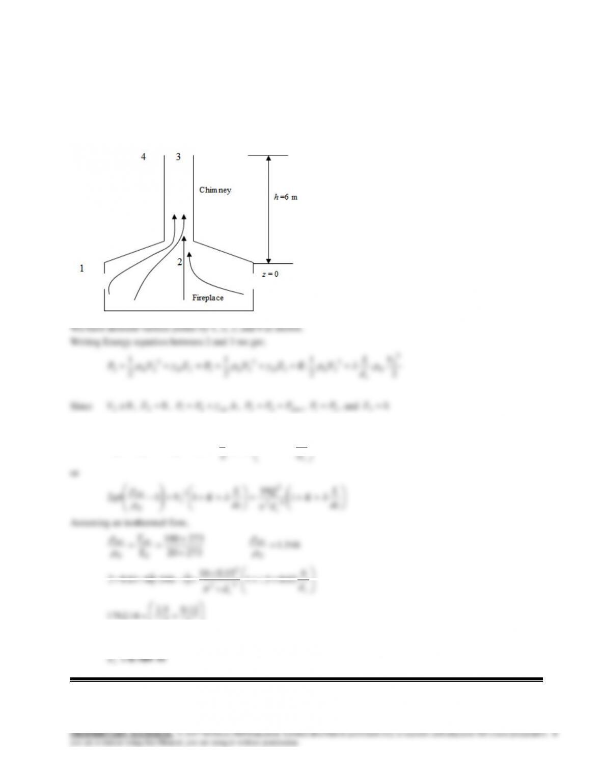
14–92
Solution A chimney is to be designed to discharge hot gases from a fireplace. The chimney diameter that would
discharge the hot gases at the desired rate is to be determined.
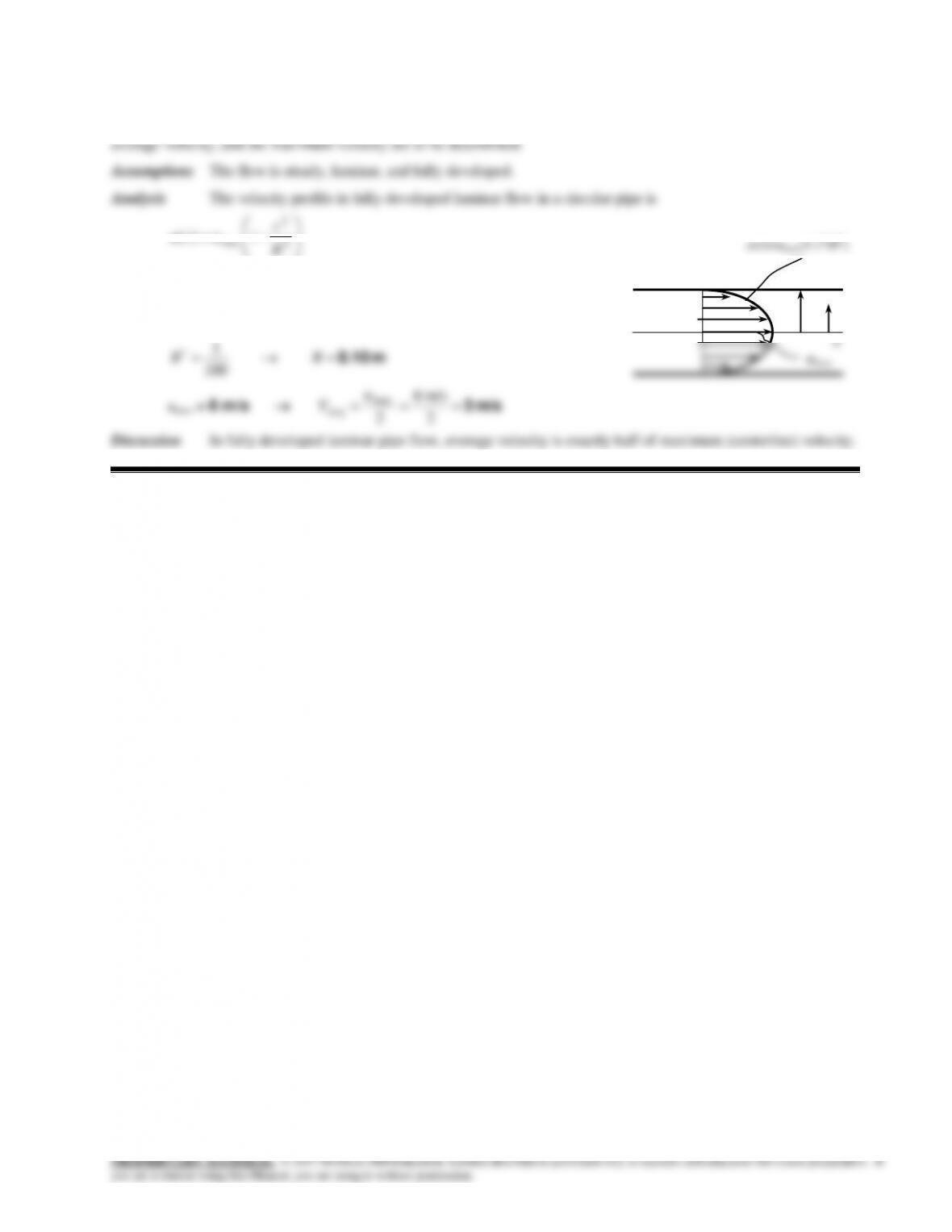
Assumptions 1 The flow is steady and incompressible. 2 The flow is fully developed.
Analysis
Bernoulli equation reduces to
c
GGatmairatm d
L
KVhPhP
1
2
1
.2
3
c
cd
d
2
c
cd
d
12.05.2
14.1762 4
This equation can be solved by try and error method, which would give
m0.194
c
d
14–74
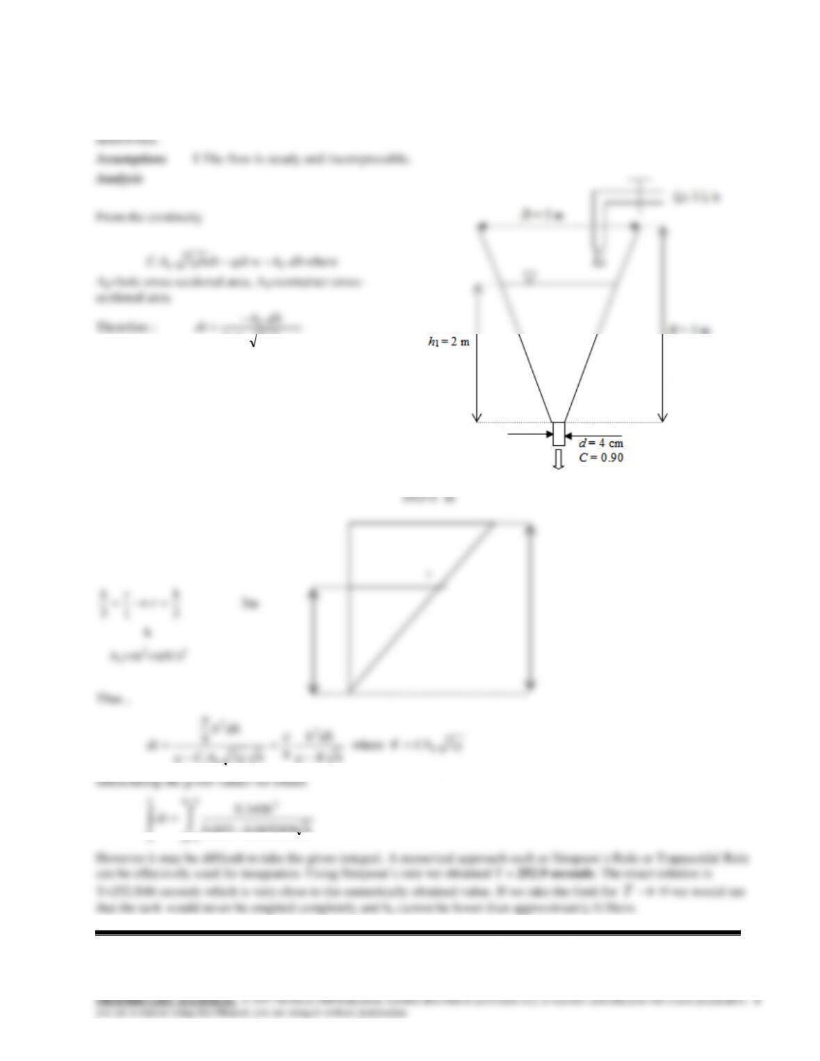
14–93
Solution An inverted conical container is filled with water. A faucet supply water into the container and water is
withdrawn from a hole at the bottom. The time it will take for the water level in the tank to drop to a specified level is to be
qghAC
h
2.
In other hand, AT=r2 at any h depth of water; that is
AT=f(h)
From the similarity;
14–75
Review Problems
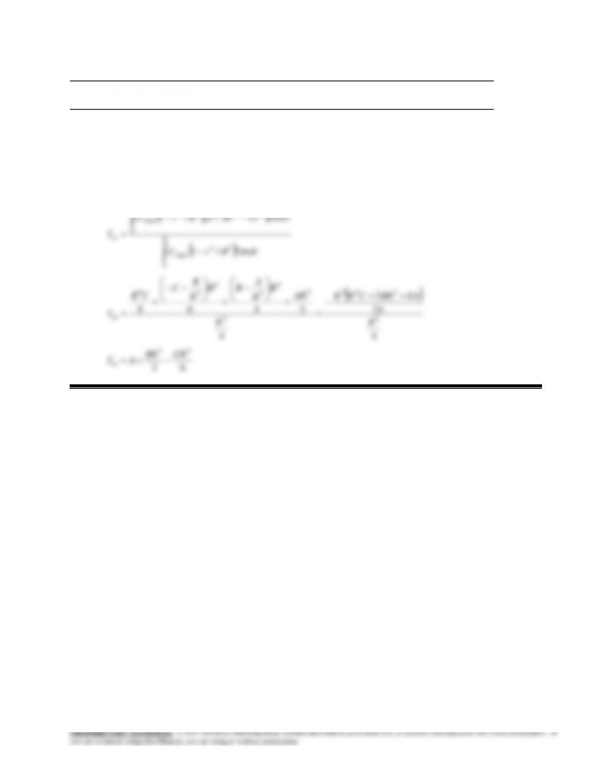
14–94
Solution The velocity and temperature profiles at a cross-section are given. A relation for the bulk fluid
temperature at that cross section is to be obtained.
Analysis
R
rdrCrBrARrU
0
4222
max
2/1
14–95
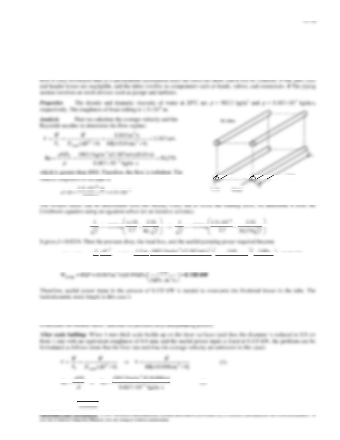
Solution Water is flowing through a brass tube bank of a heat exchanger at a specified flow rate. The pressure drop
and the pumping power required are to be determined. Also, the percent reduction in the flow rate of water through the
tubes is to be determined after scale build-up on the inner surfaces of the tubes.
Assumptions 1 The flow is steady, horizontal, and incompressible. 2 The entrance effects are negligible, and thus the
14–77
fff
D
fRe
51.2
7.3
05.0
log0.2
1
Re
51.2
7.3
/
log0.2
1
(3)
23
2
kPa1
kN1
) kg/m3.983(
m 5.1
V
V
L
14–96
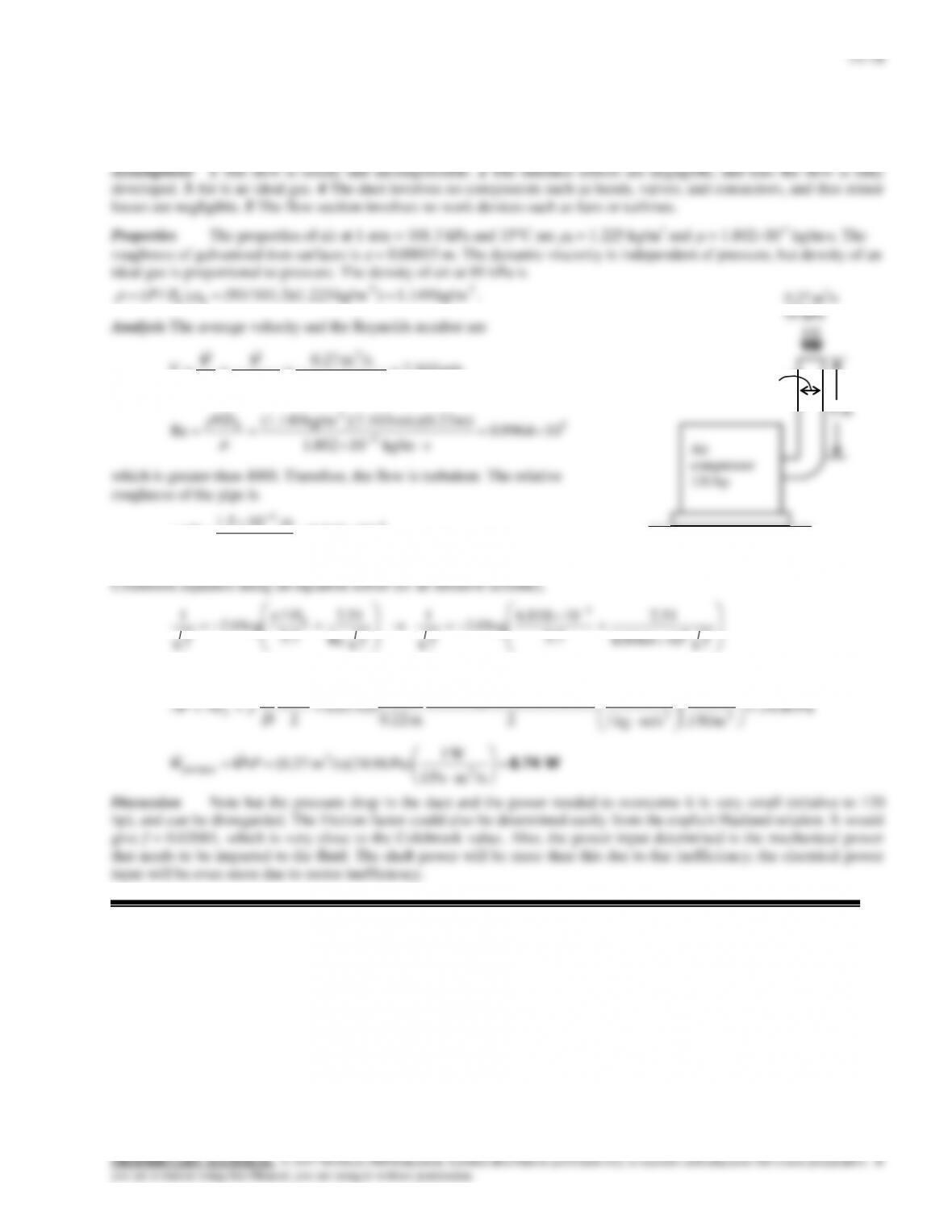
Solution A compressor takes in air at a specified rate at the outdoor conditions. The useful power used by the
compressor to overcome the frictional losses in the duct is to be determined.
m/s 103.7
4/m) (0.22
/sm 0.27
4/ 2
3
2
D
A
V
c
VV
5
5
3
109964.0
skg/m 10802.1
m) m/s)(0.22 )(7.103kg/m (1.149
Re
h
VD
which is greater than 4000. Therefore, the flow is turbulent. The relative
roughness of the pipe is
10818.6
m 22.0
m 105.1
/4
4
D
The friction factor can be determined from the Moody chart, but to avoid the reading error, we determine it from the
fff
D
f
h
5
4
109964.0
51.2
7.3
10818.6
log0.2
1
Re
51.2
7.3
/
log0.2
1
It gives f = 0.02105. Then the pressure drop in the duct and the required pumping power become
Pa 1
N 1
m/s) 103.7)(kg/m 149.1(
m 9
23
2
L
9 m
22 cm
Air
compressor
120 hp
14–79
14–97
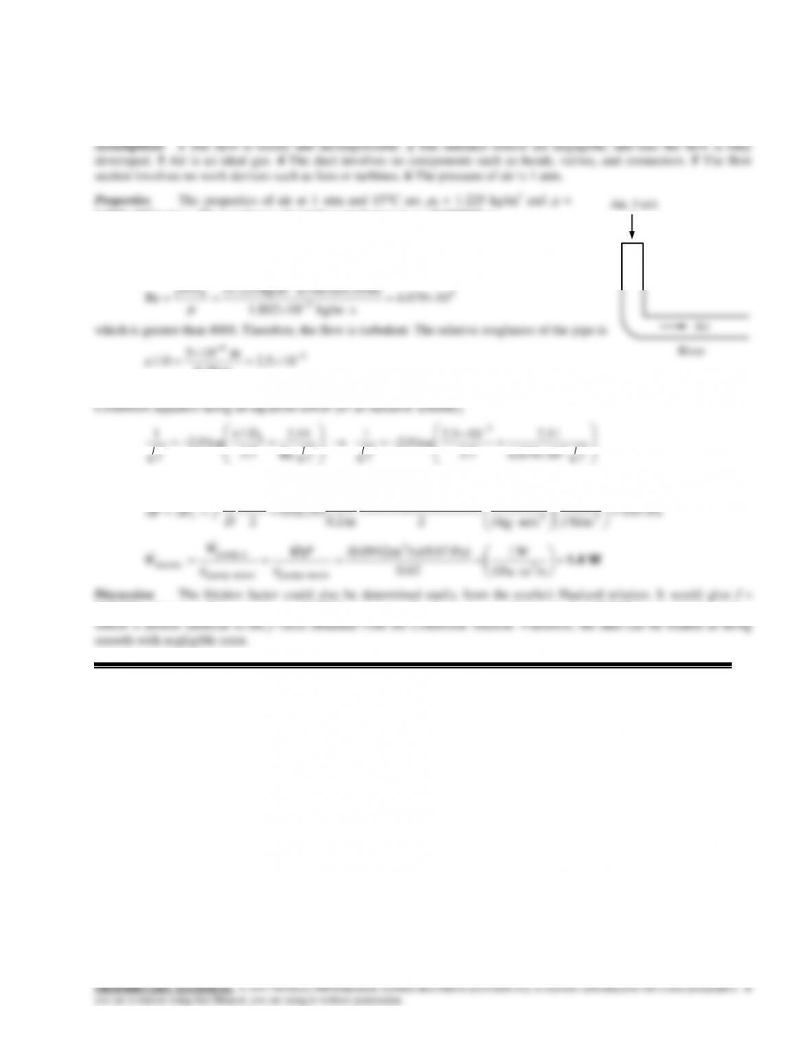
Solution Air enters the underwater section of a circular duct. The fan power needed to overcome the flow resistance
in this section of the duct is to be determined.
1.80210-5 kg/ms. The roughness of stainless steel pipes is
= 0.000005 m.
Analysis The volume flow rate and the Reynolds number are
/sm 0942.0]4/m) (0.20m/s)[ 3()4/( 322
DVVAc
V
4
5
3
10079.4
s kg/m10802.1
m) m/s)(0.20 )(3 kg/m(1.225
Re
h
VD
which is greater than 4000. Therefore, the flow is turbulent. The relative roughness of the pipe is
105.2
m 20.0
m 105
/5
6
D
The friction factor can be determined from the Moody chart, but to avoid the reading error, we determine it from the
fff
D
f
h
4
5
10079.4
51.2
7.3
105.2
log0.2
1
Re
51.2
7.3
/
log0.2
1
It gives f = 0.02195. Then the pressure drop in the duct and the required pumping power become
Pa 1
N 1
m/s) 3)( kg/m225.1(
m 15
23
2
L
River
Air
Air, 3 m/s
14–80
14–98
Solution The velocity profile in fully developed laminar flow in a circular pipe is given. The radius of the pipe, the