14–41
Piping Systems and Pump Selection
14-62C
Solution We are to discuss whether the required pump head is equal to the elevation difference when irreversible
14-63C
Solution We are to explain how the operating point of a pipe/pump system is determined.
14–64C
Solution We are to discuss whether attaching a nozzle to a garden hose will increase or decrease the filling time
14–42
14–65C
Solution We are to compare discharge times of two water tanks for two cases.
14–66C
Solution We are to compare the flow rate and pressure drop in two pipes of different diameters in series.
14–67C
Solution We are to compare the pressure drop of two different-length pipes in parallel.
14–68C
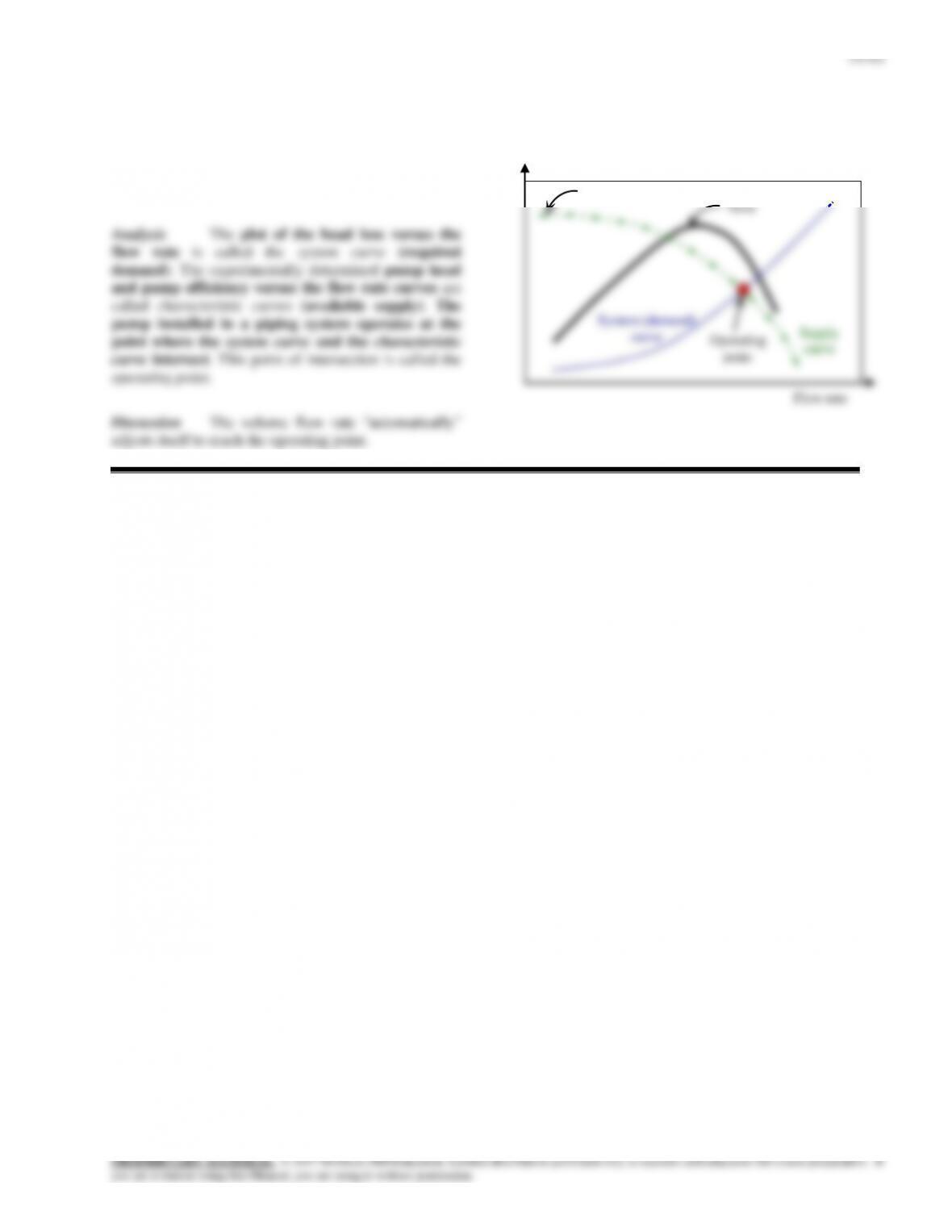
Solution We are to draw a pump head versus
flow rate chart and identify several parameters.
hpump
pump
Head
14–44
14–69
Solution Water is withdrawn from a hole at the bottom of a cylindrical tank. The time it will take for the water in
the tank to empty completely is to be determined.
Assumptions 1 The flow is steady and incompressible. 1 The Bernoulli equation is applicable.
Analysis
h2=2 m
oil
h1=2 m
14-70
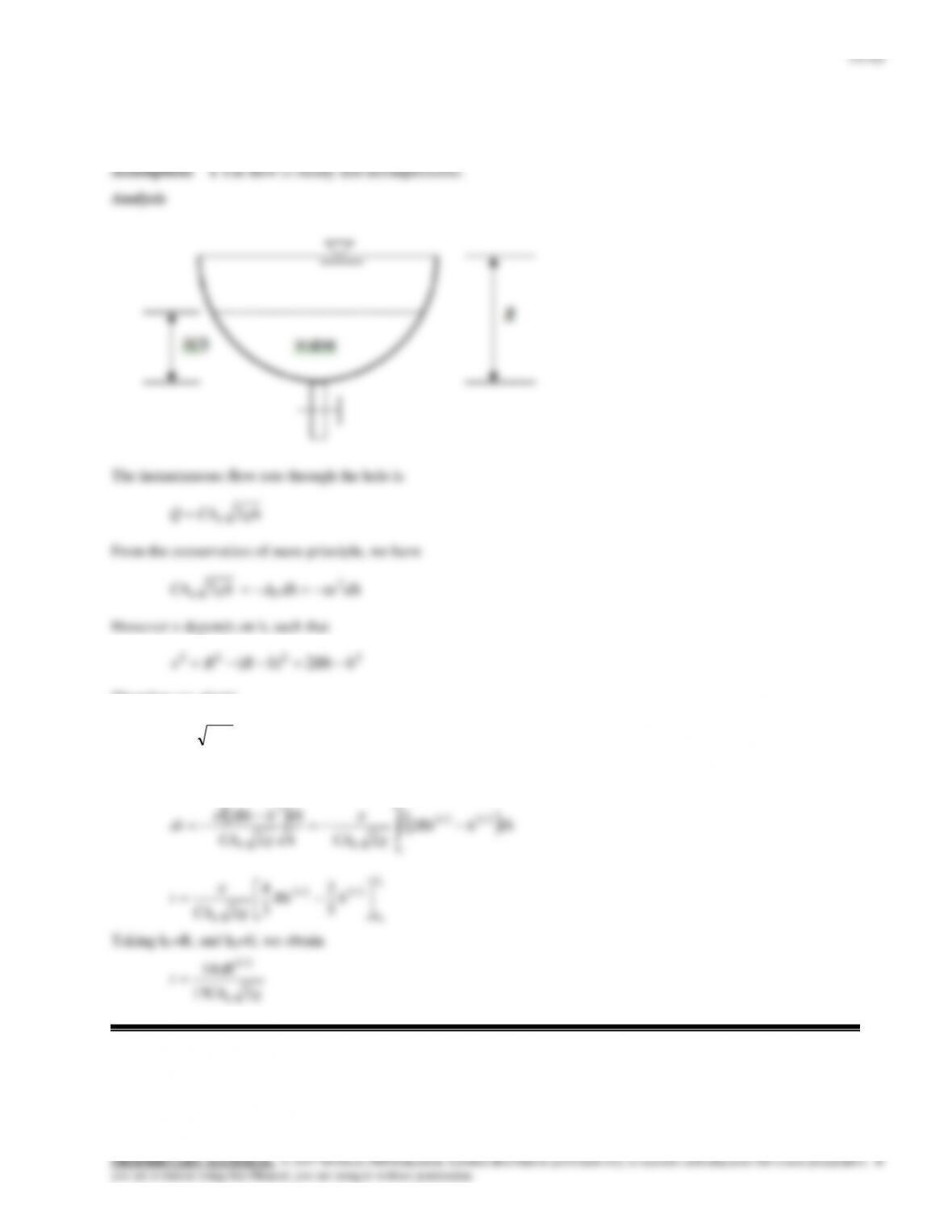
Solution Water is withdrawn from a hole at the bottom of a semi-spherical tank. An expression for the time needed to
empty the tank completely is to be determined.
Therefore we obtain
dhhRhdtghCAh
2
22
Separating variables would yield
dhhRh
gCAhgCA
dhhRh
dt
h
h
hh
2
1
2/32/1
2
2
22
2
1
2
2/52/3
5
2
3
4
2
h
h
h
hRh
gCA
t
Taking h1=R, and h2=0, we obtain
gCA
R
t
h215
14 2/5
14–46
14-71
Solution Underground water is to be pumped to a reservoir at a much higher elevation using plastic pipes. The
required power input to the pump is to be determined.
Assumptions 1 The flow is steady and incompressible. 2 The entrance effects are negligible, and thus the flow is fully
developed. 3 The total minor loss coefficient due to the use elbows, vanes, etc is estimated to be 12. 4 Water level in the
14–47
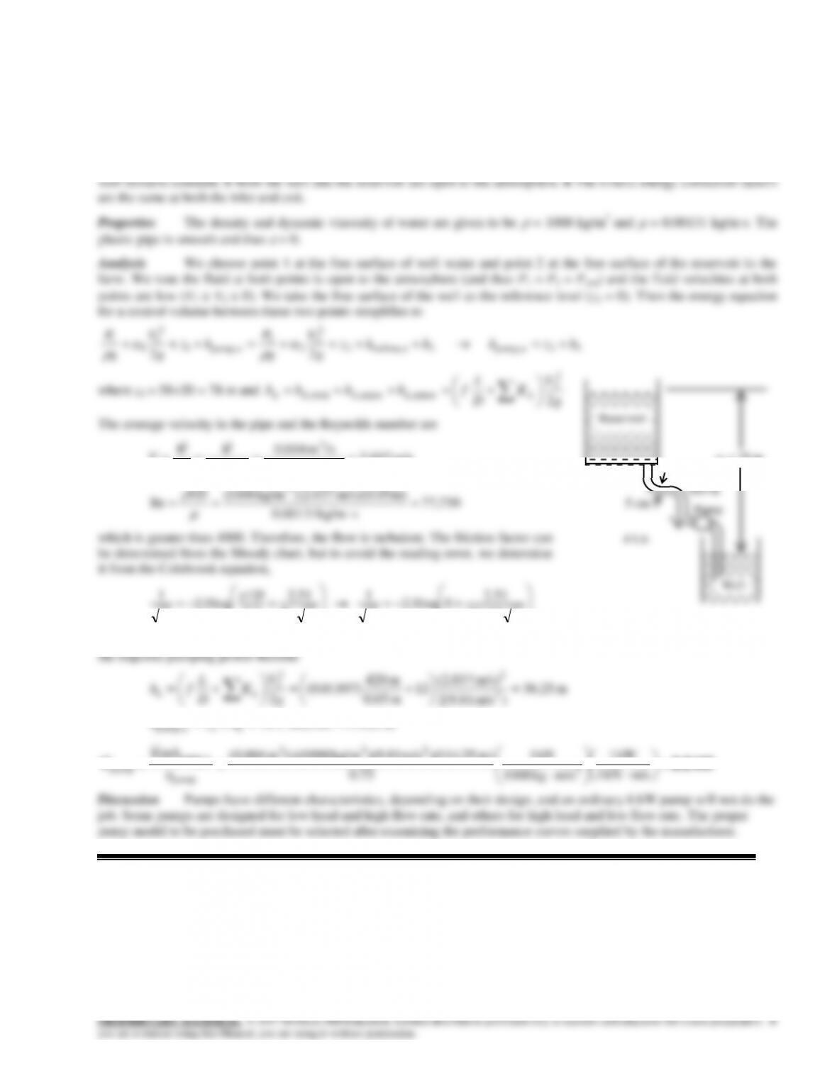
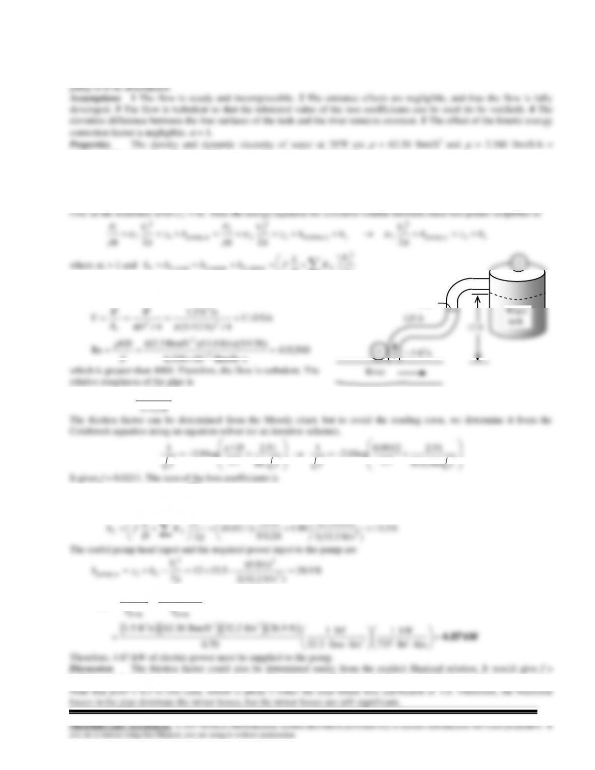
14–72E
Solution The flow rate through a piping system connecting two reservoirs is given. The elevation of the source is to
6.55610-4 lbm/fts. The roughness of cast iron pipe is
= 0.00085 ft.
Analysis The piping system involves 60 ft of 2-in diameter piping, a well-rounded entrance (KL = 0.03), 4 standard
flanged elbows (KL = 0.3 each), a fully open gate valve (KL = 0.2), and a sharp-edged exit (KL = 1.0). We choose points 1
and 2 at the free surfaces of the two reservoirs. Noting that the fluid at both points is open to the atmosphere (and thus P1 =
P2 = Patm), the fluid velocities at both points are zero (V1 = V2 =0), the free surface of the lower reservoir is the reference
g
D
since the diameter of the piping system is constant. The average velocity in the
pipe and the Reynolds number are
700,60
slbm/ft 10307.1
ft) ft/s)(2/12 64.7)(lbm/ft 3.62(
Re
ft/s 64.7
4/ft) 12/2(
/sft 10/60
4/
3
3
2
3
2
VD
D
A
V
c
VV
which is greater than 4000. Therefore, the flow is turbulent. The relative
fff
D
f700,60
51.2
7.3
0051.0
log0.2
1
Re
51.2
7.3
/
log0.2
1
43.20.12.03.0403.04 exit,valve,elbow,entrance,
LLLLL KKKKK
Then the total head loss and the elevation of the source become
ft 6.12
)ft/s 2.32(2
ft/s) 64.7(
43.2
ft 2/12
ft 60
)0320.0(
22
2
2
g
V
K
D
L
fh LL
ft 12.6 L
hz1
Therefore, the free surface of the first reservoir must be 12.6 ft above the free surface of the lower reservoir to ensure water
flow between the two reservoirs at the specified rate.
Discussion Note that fL/D = 11.5 in this case, which is about 5 folds of the total minor loss coefficient. Therefore,
ignoring the sources of minor losses in this case would result in an error of about 20%.
2 in
60 ft
z1
2
1
14-73
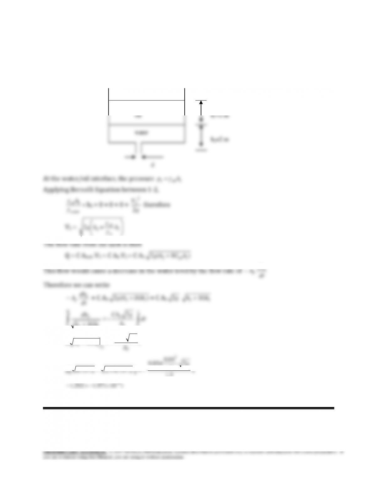
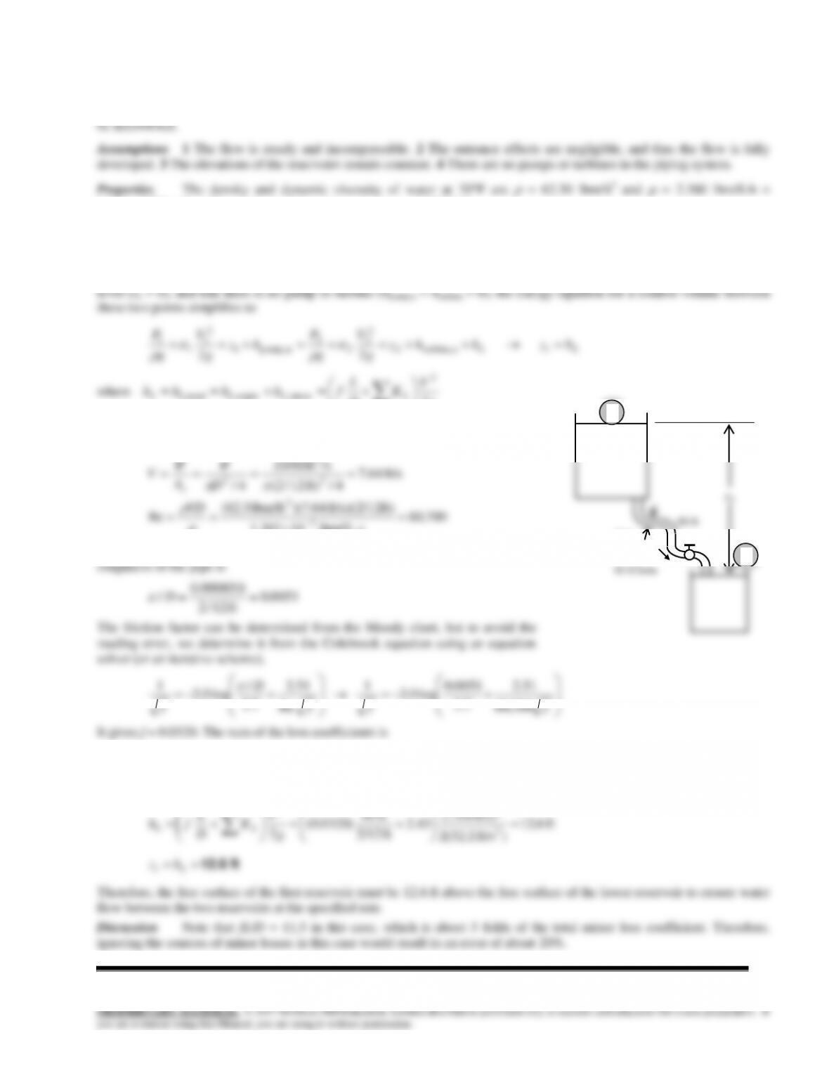
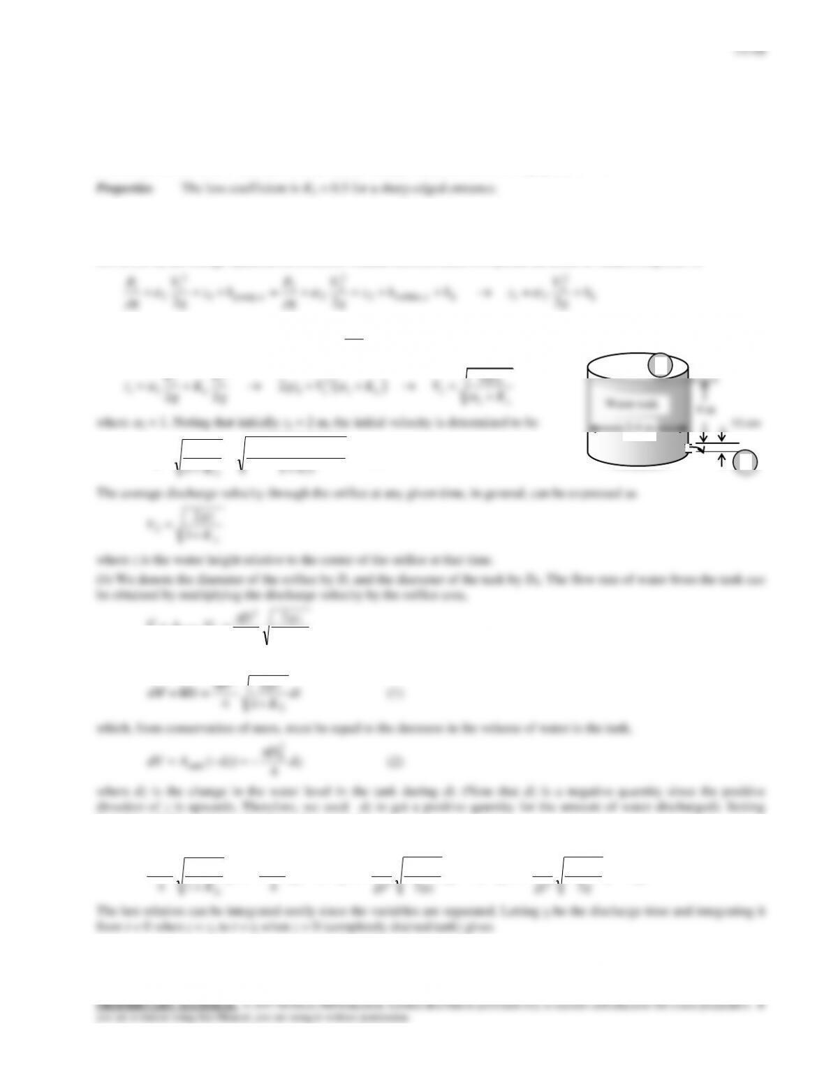
Solution A water tank open to the atmosphere is initially filled with water. A sharp-edged orifice at the bottom drains
to the atmosphere. The initial velocity from the tank and the time required to empty the tank are to be determined.
Assumptions 1 The flow is uniform and incompressible. 2 The flow is turbulent so that the tabulated value of the loss
coefficient can be used. 3 The effect of the kinetic energy correction factor is negligible,
= 1.
Analysis (a) We take point 1 at the free surface of the tank, and point 2 at the exit of the orifice. We also take the
reference level at the centerline of the orifice (z2 = 0), and take the positive direction of z to be upwards. Noting that the
fluid at both points is open to the atmosphere (and thus P1 = P2 = Patm) and that the fluid velocity at the free surface is very
low (V1 0), the energy equation for a control volume between these two points (in terms of heads) simplifies to
2
22
2
2
21e turbine,2
2
2
2
2
upump,1
2
1
1
1
LL h
g
V
zhhz
g
V
g
P
hz
g
V
g
P
where the head loss is expressed as
g
V
Kh LL 2
2
. Substituting and solving for V2 gives
22
2
2 2 1
1 2 1 2 2 2
2
2
2
22
LL
L
V V gz
z K gz V K V
g g K
where
2 = 1. Noting that initially z1 = 2 m, the initial velocity is determined to be
m/s 7.23
0.51
m) 4)(m/s 81.9(2
1
22
1
2
L
K
gz
V
L
K
gz
D
VAV
1
2
4
2
2orifice
Then the amount of water that flows through the orifice during a differential time interval dt is
dt
K
gz
D
dtd
L
1
2
4
2
VV
(1)
which, from conservation of mass, must be equal to the decrease in the volume of water in the tank,
dz
D
dzAdV 4
)(
2
0
tank
(2)
where dz is the change in the water level in the tank during dt. (Note that dz is a negative quantity since the positive
direction of z is upwards. Therefore, we used –dz to get a positive quantity for the amount of water discharged). Setting
Eqs. (1) and (2) equal to each other and rearranging,
dzz
g
K
D
D
dtdz
gz
K
D
D
dtdz
D
dt
K
gz
DLL
L
2/1
2
2
0
2
2
0
2
0
2
2
1
2
1
41
2
4
Water tank
4 m
10 cm
2.4 m
1
2
14–49
2/1
1
2
2
0
0
2
1
1
2
2
0
0
2/1
2
2
0
0 2
1
2
1
2
1
–
2
1
1
2
1
1
z
g
K
D
D
z
g
K
D
D
tdzz
g
K
D
D
dt L
z
L
f
zz
L
t
t
f
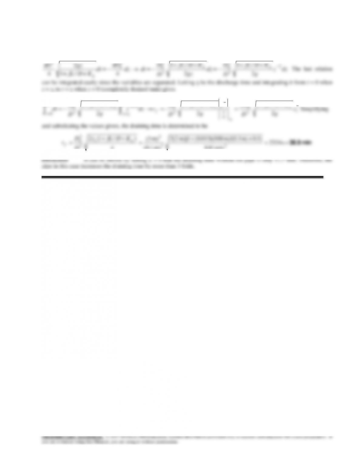
Simplifying and substituting the values given, the draining time is determined to be
min 10.6 s 637
22
2
1
2
2
0
m/s 81.9
0.5)m)(1 4(2
m) 1.0(
m) 4.2(
)1(2
g
Kz
D
D
tL
f
Discussion The effect of the loss coefficient KL on the draining time can be assessed by setting it equal to zero in the
min 8.7 s 520
m/s 81.9
m) 4(2
m) 1.0(
m) 4.2(
2
22
2
1
2
2
0
loss zero, g
z
D
D
tf
14–74
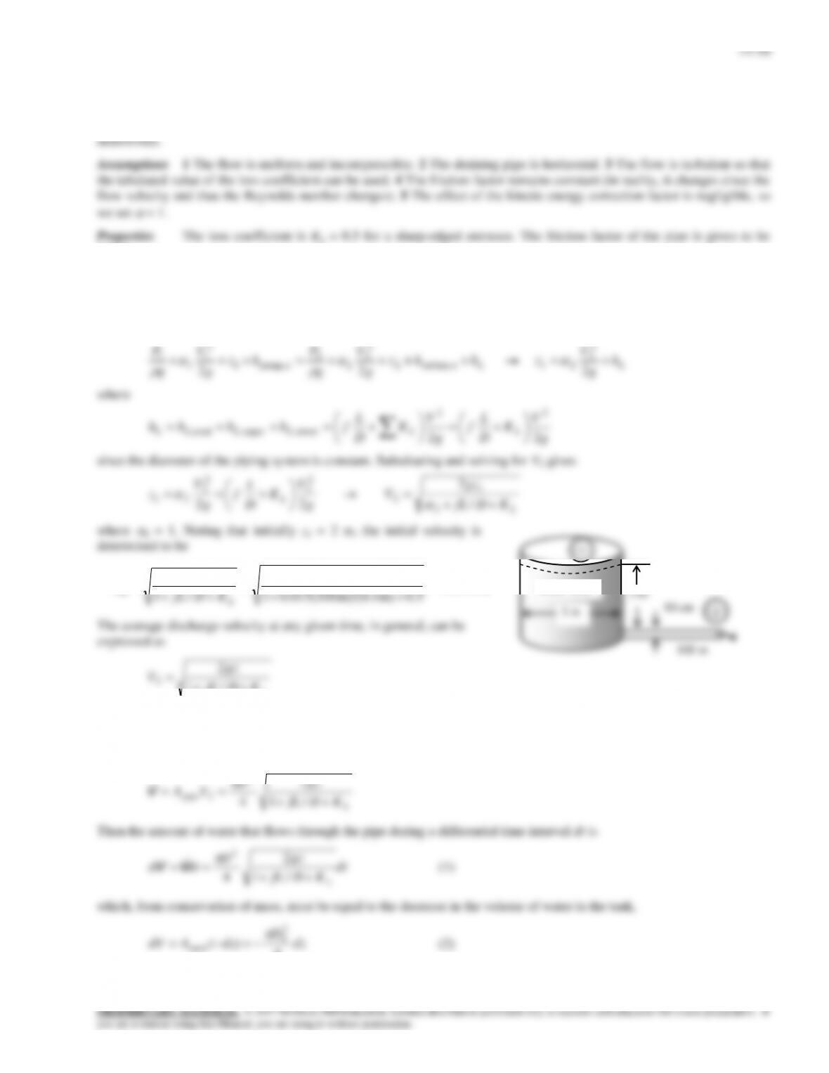
Solution A water tank open to the atmosphere is initially filled with water. A sharp-edged orifice at the bottom drains
to the atmosphere through a long pipe. The initial velocity from the tank and the time required to empty the tank are to be
0.015.
Analysis (a) We take point 1 at the free surface of the tank, and point 2 at the exit of the pipe. We take the reference
level at the centerline of the pipe (z2 = 0), and take the positive direction of z to be upwards. Noting that the fluid at both
points is open to the atmosphere (and thus P1 = P2 = Patm) and that the fluid velocity at the free surface is very low (V1 0),
the energy equation for a control volume between these two points (in terms of heads) simplifies to
2
22
2
2
21e turbine,2
2
2
2
2
upump,1
2
1
1
1
LL h
g
V
zhhz
g
V
g
P
hz
g
V
g
P
where
g
V
K
D
L
f
g
V
K
D
L
fhhhh LLLLLL 22
22
minor,major,total,
since the diameter of the piping system is constant. Substituting and solving for V2 gives
L
LKDfL
gz
V
g
V
K
D
L
f
g
V
z
/
2
22 2
1
2
2
2
2
2
21
where
2 = 1. Noting that initially z1 = 2 m, the initial velocity is
determined to be
m/s 1.54
0.5m) m)/(0.1 0.015(1001
m) 2)(m/s 81.9(2
/1
22
1
,2
L
iKDfL
gz
V
L
KDfL
gz
V
/1
2
2
where z is the water height relative to the center of the orifice at that time.
(b) We denote the diameter of the pipe by D, and the diameter of the tank by Do. The flow rate of water from the tank can
be obtained by multiplying the discharge velocity by the pipe cross-sectional area,
L
pipe KDfL
gz
D
VA
/1
2
4
2
2
V
Then the amount of water that flows through the pipe during a differential time interval dt is
dt
KDfL
gz
D
dtd
L
/1
2
4
2
VV
(1)
which, from conservation of mass, must be equal to the decrease in the volume of water in the tank,
dz
D
dzAdV k4
)(
2
0
tan
(2)
Water tank
2 m
10 cm
3 m
100 m
1
2
14–51
where dz is the change in the water level in the tank during dt. (Note that dz is a negative quantity since the positive
direction of z is upwards. Therefore, we used –dz to get a positive quantity for the amount of water discharged). Setting
Eqs. (1) and (2) equal to each other and rearranging,
dzz
g
KDfL
D
D
dz
gz
KDfL
D
D
dtdz
D
dt
KDfL
gz
DLL
L
2
1
2
/1
2
/1
4/1
2
42
2
0
2
2
0
2
0
2
The last relation
can be integrated easily since the variables are separated. Letting tf be the discharge time and integrating it from t = 0 when
z = z1 to t = tf when z = 0 (completely drained tank) gives
2
1
1
2
1
1
1
2
2
0
0
2
12
2
0
0
2/1
2
2
0
0 2
/1
2
2
/1
–
2
/1
z
g
KDfL
D
D
z
g
KDfL
D
D
tdzz
g
KDfL
D
D
dt L
z
L
f
zz
L
t
t
f
Simplifying
and substituting the values given, the draining time is determined to be
min 38.9
s 2334
m/s 81.9
0.5]m) m)/(0.1 100)(015.0(m)[1 2(2
m) 1.0(
m) 3(
)/1(2
22
2
1
2
2
0
g
KDfLz
D
D
tL
f
Discussion It can be shown by setting L = 0 that the draining time without the pipe is only 11.7 min. Therefore, the
pipe in this case increases the draining time by more than 3 folds.
14–52
14–75
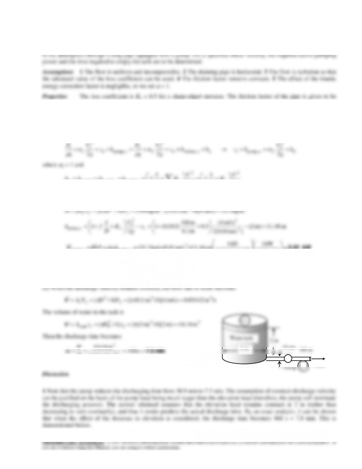
Solution A water tank open to the atmosphere is initially filled with water. A sharp-edged orifice at the bottom drains
0.015. The density of water at 30C is
= 996 kg/m3.
Analysis (a) We take point 1 at the free surface of the tank, and point 2 at the exit of the pipe. We take the reference
level at the centerline of the orifice (z2 = 0), and take the positive direction of z to be upwards. Noting that the fluid at both
points is open to the atmosphere (and thus P1 = P2 = Patm) and that the fluid velocity at the free surface is very low (V1 0),
the energy equation for a control volume between these two points (in terms of heads) simplifies to
2
22
2
2
2 upump,1e turbine,2
2
2
2
2
upump,1
2
1
1
1
LL h
g
V
hzhhz
g
V
g
P
hz
g
V
g
P
where
2 = 1 and
g
V
K
D
L
f
g
V
K
D
L
fhhhh LLLLLL 22
22
minor,major,total,
since the diameter of the piping system is constant. Substituting and noting that the initial discharge velocity is 4 m/s, the
required useful pumping head and power are determined to be
323
2
2
2 kg/m3.31)m/s 4(/4]m) 1.0()[ kg/m996()4/(
VDVAm c
m 46.11m) 2(
)m/s 2(9.81
m/s) 4(
5.0
m 0.1
m 100
)015.0(1
2
12
2
1
2
2
upump,
z
g
V
K
D
L
fh L
kW 3.52
m/skN 1
kW 1
m/skg 1000
kN 1
m) 46.11)(m/s 81.9)(kg/s 3.31(2
2
u pump,u pump, ghmPW
V
Therefore, the pump must supply 3.52 kW of mechanical energy to water. Note that the shaft power of the pump must be
greater than this to account for the pump inefficiency.
14–53
PROPRIETARY MATERIAL. © 2017 McGraw-Hill Education. Limited distribution permitted only to teachers and educators for course preparation. If
2 The required pump head (of water) is 11.46 m, which is more than 10.3 m of water column which corresponds to the
atmospheric pressure at sea level. If the pump exit is at 1 atm, then the absolute pressure at pump inlet must be negative ( =
-1.16 m or – 11.4 kPa), which is impossible. Therefore, the system cannot work if the pump is installed near the pipe exit,
and cavitation will occur long before the pipe exit where the pressure drops to 4.2 kPa and thus the pump must be installed
close to the pipe entrance. A detailed analysis is given below.
Demonstration 1 for Prob. 14–84 (extra) (the effect of drop in water level on discharge time)
Noting that the water height z in the tank is variable, the average discharge velocity through the pipe at any given time, in
the cross-sectional area of the pipe,
L
pipe KDfL
hzg
D
VA
/1
)(2
4
upump,
2
2
V
dz
D
dzAd k4
)(
2
0
tan
V
(2)
where dz is the change in the water level in the tank during dt. (Note that dz is a negative quantity since the positive
direction of z is upwards. Therefore, we used –dz to get a positive quantity for the amount of water discharged). Setting
Eqs. (1) and (2) equal to each other and rearranging,
dzhz
g
KDfL
D
D
dtdz
D
dt
KDfL
hzg
DL
L
2
1
)(
2
/1
4/1
)(2
4up ump,
2
2
0
2
0
up ump,
2
The last relation can be integrated easily since the variables are separated. Letting tf be the discharge time and integrating it
from t = 0 when z = z1 to t = tf when z = 0 (completely drained tank) gives
0
2/1
upump,
2
2
0
0 1
)(
2
/1
zz
L
t
t
dzhz
g
KDfL
D
D
dt
f
g
KDfLh
g
KDfLhz
D
D
hz
g
KDfL
D
D
tLL
z
L
f
)/1(2)/1)((2)(
2
/1
– pumppump1
2
2
0
0
2
1
pump
2
2
0
1
2
1
Substituting the
min 7.8
s 468
m/s 81.9
0.5]/0.1100015.0m)[1 46.11(2
m/s 81.9
0.5]/0.1100015.0m)[1 46.112(2
m) 1.0(
m) 3(
222
2
f
t
14–54
have z1 z2 and V1 V2. The pump is located near the pipe exit, and thus the pump exit pressure is equal to the pressure at
the pipe exit, which is the atmospheric pressure, P2 = Patm. Also, the can take hL = 0 since the frictional effects and loses in
the pump are accounted for by the pump efficiency. Then the energy equation for the pump (in terms of heads) reduces to
22
atm
upump,
abs,1
e turbine,2
2
2
2
2
upump,1
2
1
1
1
g
P
h
g
P
hhz
g
V
g
P
hz
g
V
g
P
L
Solving for P1 and substituting,
kPa 10.7–
22
23
u pump,atmabs,1
kN/m 1
kPa 1
m/skg 1000
kN 1
m) 46.11)(m/s 81.9)(kg/m 996(kPa) 3.101(
ghPP
which is impossible (absolute pressure cannot be negative). The technical answer to the question is that cavitation will
occur since the pressure drops below the vapor pressure of 4.246 kPa. The practical answer is that the question is invalid
2
*
22
2
atm
upump,
abs,1
e turbine,2
2
2
2
2
upump,1
2
1
1
1
g
V
D
L
f
g
P
h
g
P
hhz
g
V
g
P
hz
g
V
g
P
L
atmabs,1
2
*h
PP
V
L
14–55
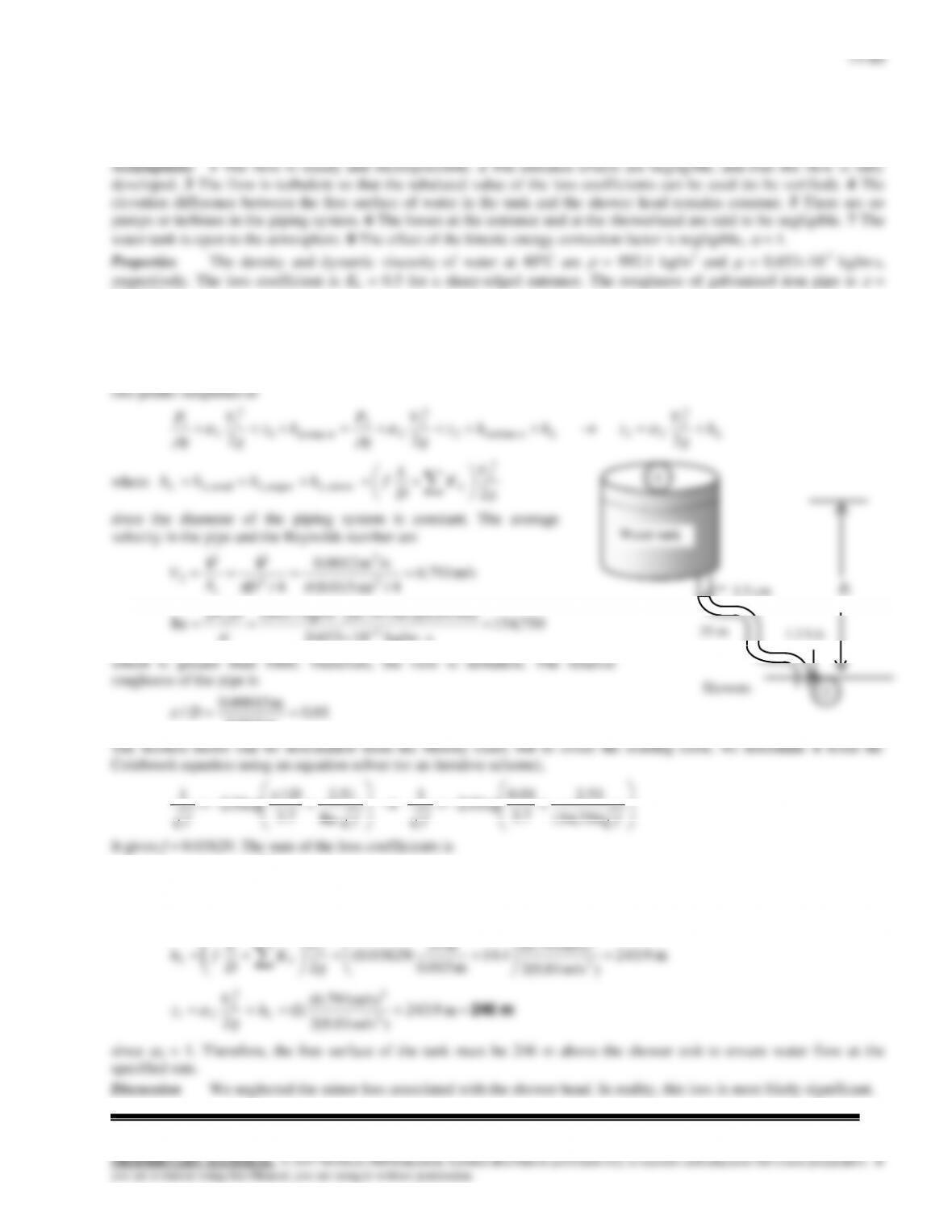
14–76
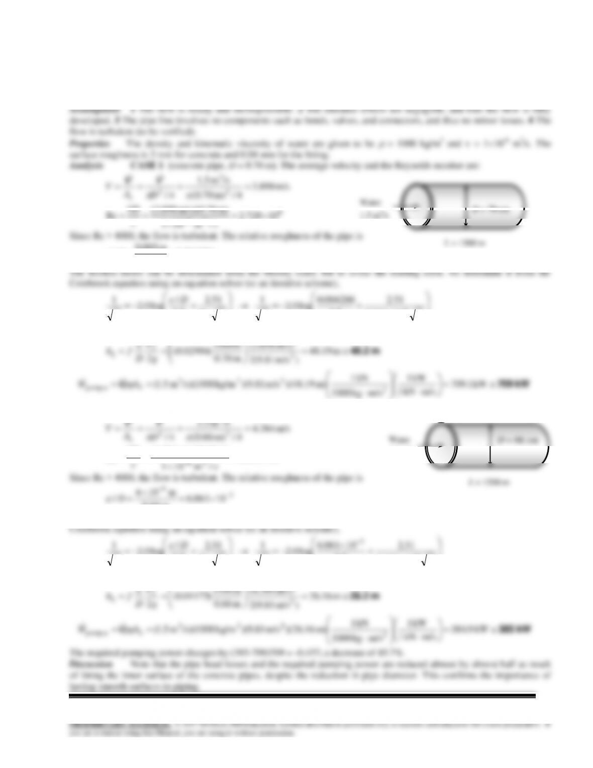
Solution Water is transported to a residential area through concrete pipes, and the idea of lining the interior surfaces
of the pipe is being evaluated to reduce frictional losses. The percent increase or decrease in the pumping power
requirements as a result of lining the concrete pipes is to be determined.
14–77
Solution Water is drained from a large reservoir through two pipes connected in series. The discharge rate of water
from the reservoir is to be determined.
Assumptions 1 The flow is steady and incompressible. 2 The pipes are horizontal. 3 The entrance effects are negligible,
and thus the flow is fully developed. 4 The flow is turbulent so that the tabulated value of the loss coefficients can be used.
equation for a control volume between these two points (in terms of heads) simplifies to
2
2
2
2
2
2
1
1
V
V
P
V
P
14–58
14–78E
Solution The flow rate through a piping system between a river and a storage tank is given. The power input to the
6.55610-4 lbm/fts. The roughness of galvanized iron pipe is
= 0.0005 ft.
Analysis The piping system involves 125 ft of 5-in diameter piping, an entrance with negligible loses, 3 standard
flanged 90 smooth elbows (KL = 0.3 each), and a sharp-edged exit (KL = 1.0). We choose points 1 and 2 at the free surfaces
of the river and the tank, respectively. We note that the fluid at both points is open to the atmosphere (and thus P1 = P2 =
Patm), and the fluid velocity is 6 ft/s at point 1 and zero at point 2 (V1 = 6 ft/s and V2 =0). We take the free surface of the
g
D
since the diameter of the piping system is constant. The average velocity in the
pipe and the Reynolds number are
ft/s 0.11
4/ft) 12/5(
/sft 1.5
4/
2
3
2
D
A
V
c
VV
0012.0
ft 12/5
ft 0005.0
/D
fff
D
f500,435
51.2
7.3
0012.0
log0.2
1
Re
51.2
7.3
/
log0.2
1
9.10.13.0303 exit,elbow,entrance,
LLLL KKKK
Then the total head loss becomes
ft 5.15
)ft/s 2.32(2
ft/s) 0.11(
90.1
ft 5/12
ft 125
)0211.0(
22
2
2
g
V
K
D
L
fh LL
The useful pump head input and the required power input to the pump are
ft 9.26
)ft/s 2.32(2
ft/s) 6(
5.1512
2
2
2
2
1
2 up ump, g
V
hzh L
pump, u pump, u
pump
pump pump
3 3 2
2
1 5 ft /s 62 30 lbm/ft 32 2 ft/s 26 9 ft 1 lbf 1 kW
0 70 737 lbf ft/s
32.2 lbm ft/s
W gh
W
. . . .
.
V
4.87 kW
Therefore, 4.87 kW of electric power must be supplied to the pump.
Discussion The friction factor could also be determined easily from the explicit Haaland relation. It would give f =
0.0211, which is identical to the calculated value. The friction coefficient would drop to 0.0135 if smooth pipes were used.
12 ft
5 in
125 ft
Water
tank
14–79E
g=32.2
rho=62.30
nu=mu/rho
eff=0.70
Vdot= 1.5
V1=6
eps1=0.0005
KL= 1.9
HL=(f1*(L/D)+KL)*(V2^2/(2*g))
hpump=z2+HL-V1^2/(2*32.2)
Wpump=(Vdot*rho*hpump)/eff/737
EES Hint: You may need to set the initial guess for variable f1 as 0.02 and Re as 1000 or something reasonable in
14-80
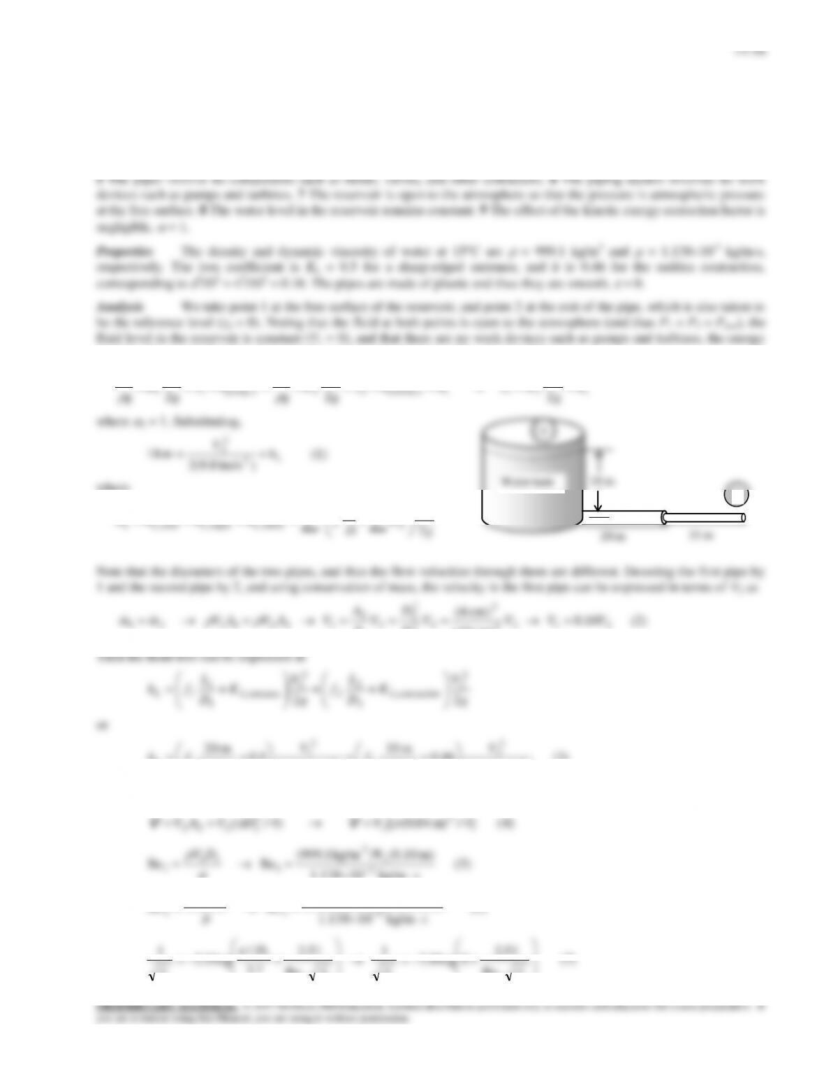
Solution A solar heated water tank is to be used for showers using gravity driven flow. For a specified flow rate, the
elevation of the water level in the tank relative to showerhead is to be determined.
0.00015 m.
Analysis The piping system involves 20 m of 1.5-cm diameter piping, an entrance with negligible loss, 4 miter bends
(90) without vanes (KL = 1.1 each), and a wide open globe valve (KL = 10). We choose point 1 at the free surface of water
in the tank, and point 2 at the shower exit, which is also taken to be the reference level (z2 = 0). The fluid at both points is
open to the atmosphere (and thus P1 = P2 = Patm), and V1 = 0. Then the energy equation for a control volume between these