14–21
14–39
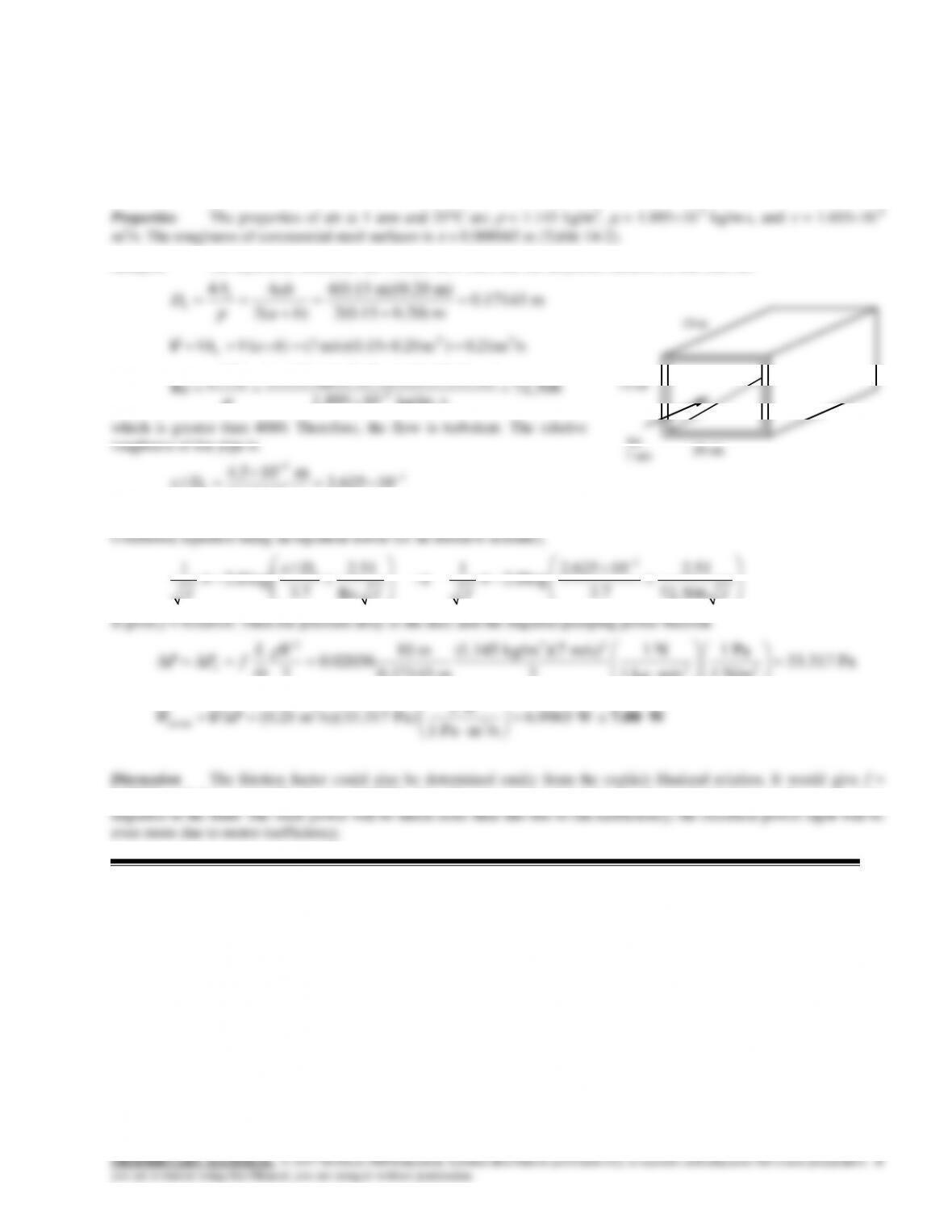
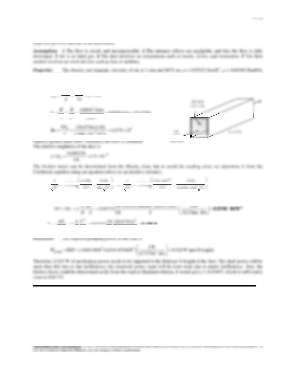
Solution Air enters a rectangular duct. The fan power needed to overcome the pressure losses is to be determined.
Assumptions 1 The flow is steady and incompressible. 2 The entrance effects are negligible, and thus the flow is fully
developed. 3 Air is an ideal gas. 4 The duct involves no components such as bends, valves, and connectors. 5 The flow
section involves no work devices such as fans or turbines
Analysis The hydraulic diameter, the volume flow rate, and the Reynolds number in this case are
44 4(0.15 m)(0.20 m) 0.17143 m
2( ) 2(0.15 0.20) m
c
h
Aab
Dp a b
/sm 21.0)m 0.20m/s)(0.15 7()( 32 baVVAc
V
3
(1.145 kg/m )(7 m/s)(0.17143 m)
h
VD
10 m
15 cm
14-40E
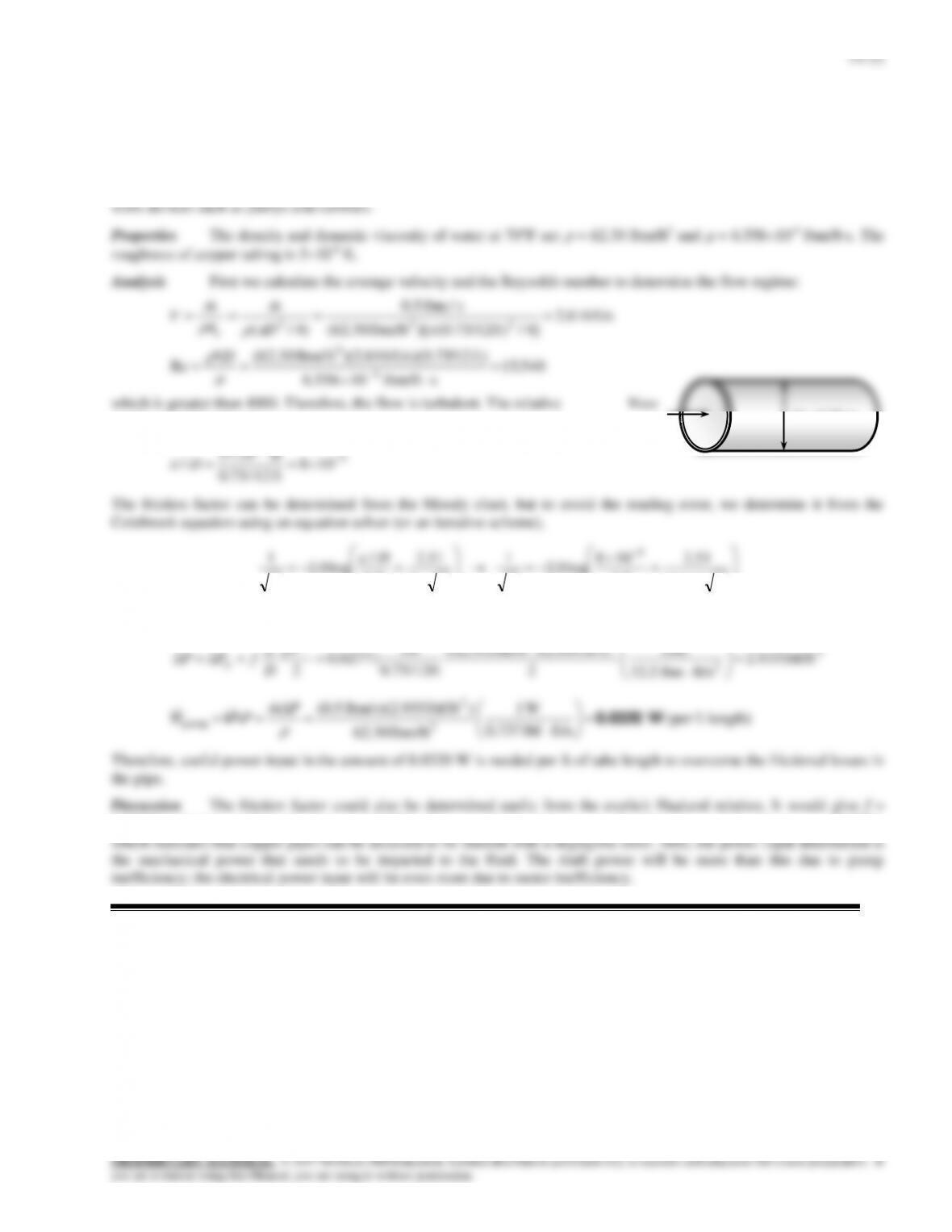
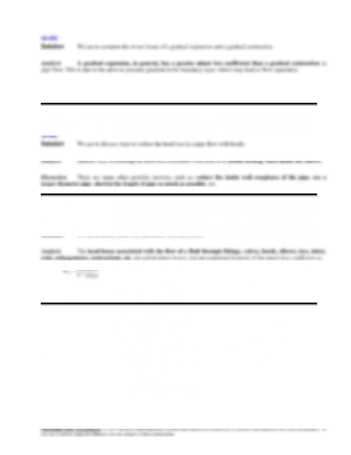
Solution Water passes through copper tubes at a specified rate. The pumping power required per ft length to maintain
flow is to be determined.
Assumptions 1 The flow is steady and incompressible. 2 The entrance effects are negligible, and thus the flow is fully
developed. 3 The pipe involves no components such as bends, valves, and connectors. 4 The piping section involves no
roughness of the pipe is
108
ft 12/75.0
ft 105
/5
6
D
The friction factor can be determined from the Moody chart, but to avoid the reading error, we determine it from the
Colebrook equation using an equation solver (or an iterative scheme),
fff
D
f540,15
51.2
7.3
108
log0.2
1
Re
51.2
7.3
/
log0.2
15
It gives f = 0.02771. Then the pressure drop and the required power input become
2
2
23
2
lbf/ft 935.2
ft/slbm 2.32
lbf 1
2
ft/s) 616.2)(lbm/ft 30.62(
ft 0.75/12
ft 1
02771.0
2
V
D
L
fPP L
length)ft (per
ft/slbf 0.737
W1
lbm/ft 30.62
)lbf/ft 935.2)(lbm/s 5.0(
3
2
pump W0.0320
Pm
PW
V
Therefore, useful power input in the amount of 0.0320 W is needed per ft of tube length to overcome the frictional losses in
the pipe.
Discussion The friction factor could also be determined easily from the explicit Haaland relation. It would give f =
0.02757, which is sufficiently close to 0.02771. Also, the friction factor corresponding to = 0 in this case is 0.02756,
D = 0.75 in
0.5 lbm/s
14-41
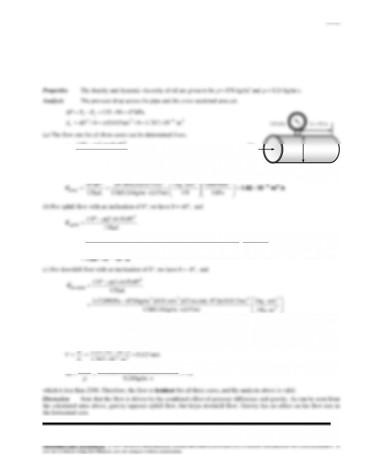
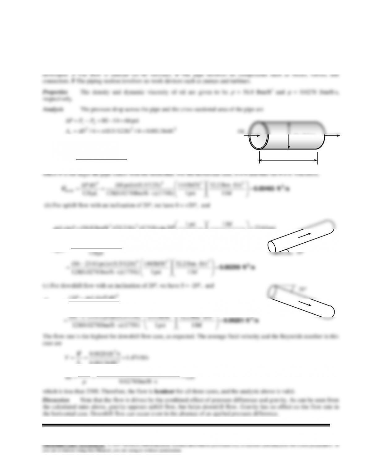
Solution The pressure of oil in a pipe which discharges into the atmosphere is measured at a certain location. The
flow rates are to be determined for 3 different orientations.
Assumptions 1 The flow is steady and incompressible. 2 The entrance effects are negligible, and thus the flow is fully
developed. 3 The flow is laminar (to be verified). 4 The pipe involves no components such as bends, valves, and
connectors. 5 The piping section involves no work devices such as pumps and turbines.
L
DgLP
128
)sin( 4
V
where is the angle the pipe makes with the horizontal. For the horizontal
case, = 0 and thus sin = 0. Therefore,
/sm 101.62 35
kPa 1
N/m 1000
N 1
m/skg 1
m) s)(15kg/m 24.0(128
m) (0.015kPa) 47(
128
2
24
4
horiz
L
DP
V
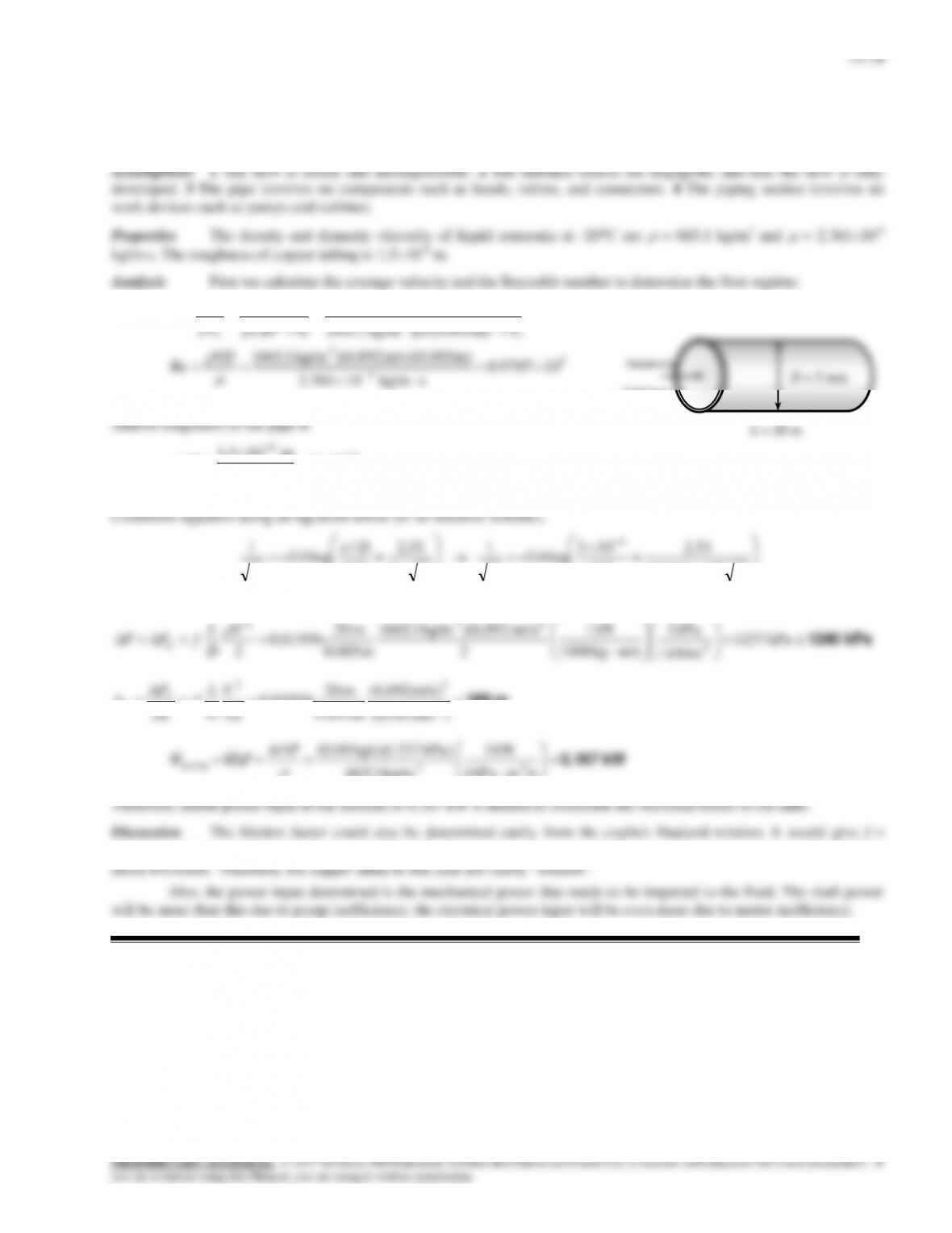
(b) For uphill flow with an inclination of 8, we have = +8, and
/sm 101.00 35
2
2423
4
uphill
mPa 1
m/skg 1
m) s)(15kg/m 24.0(128
)m 015.0(]8sin)m 15)(m/s 81.9)(kg/m 876(Pa 000,47[(
128
)sin(
L
DgLP
V
/sm 102.24 35
2
mPa 1
m) s)(15kg/m 24.0(128
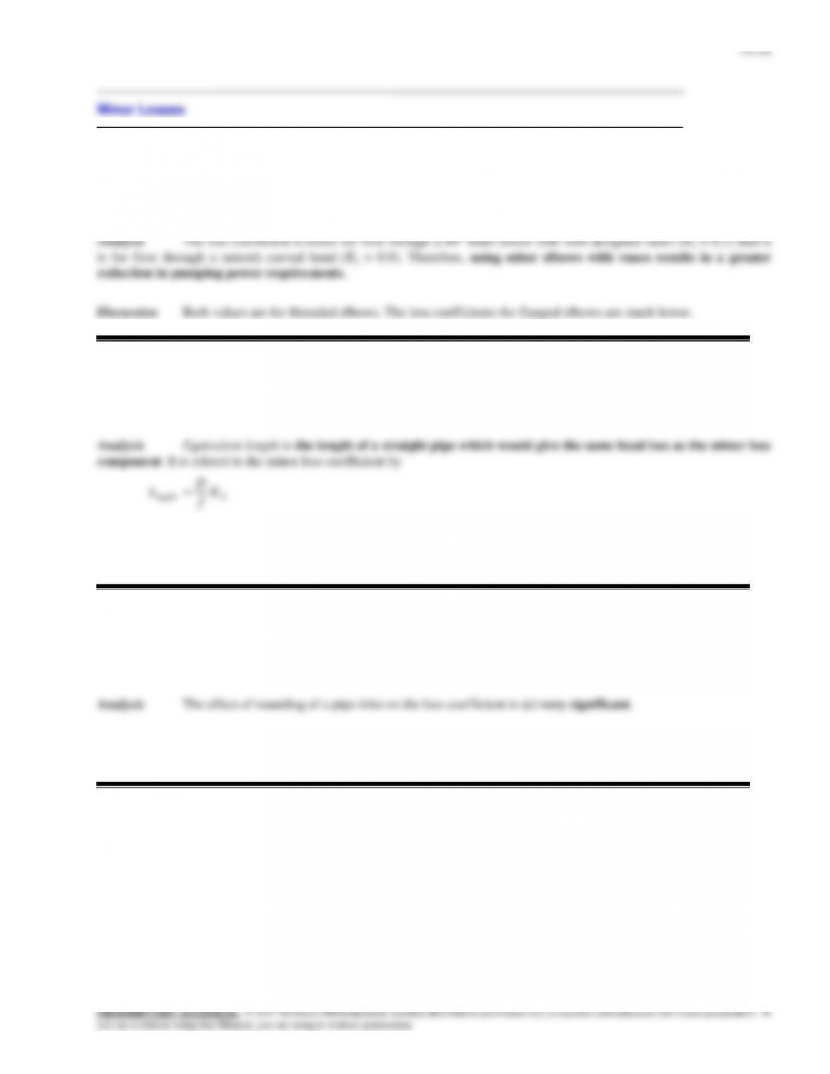
The flow rate is the highest for downhill flow case, as expected. The average fluid velocity and the Reynolds number in this
case are
0.7
s kg/m24.0
m) m/s)(0.015 127.0)( kg/m876(
Re
m/s 127.0
m 101.767
/sm.1024.2
3
24–
35
VD
A
V
c
V
Oil
D = 1.5 cm
14–24
14-42
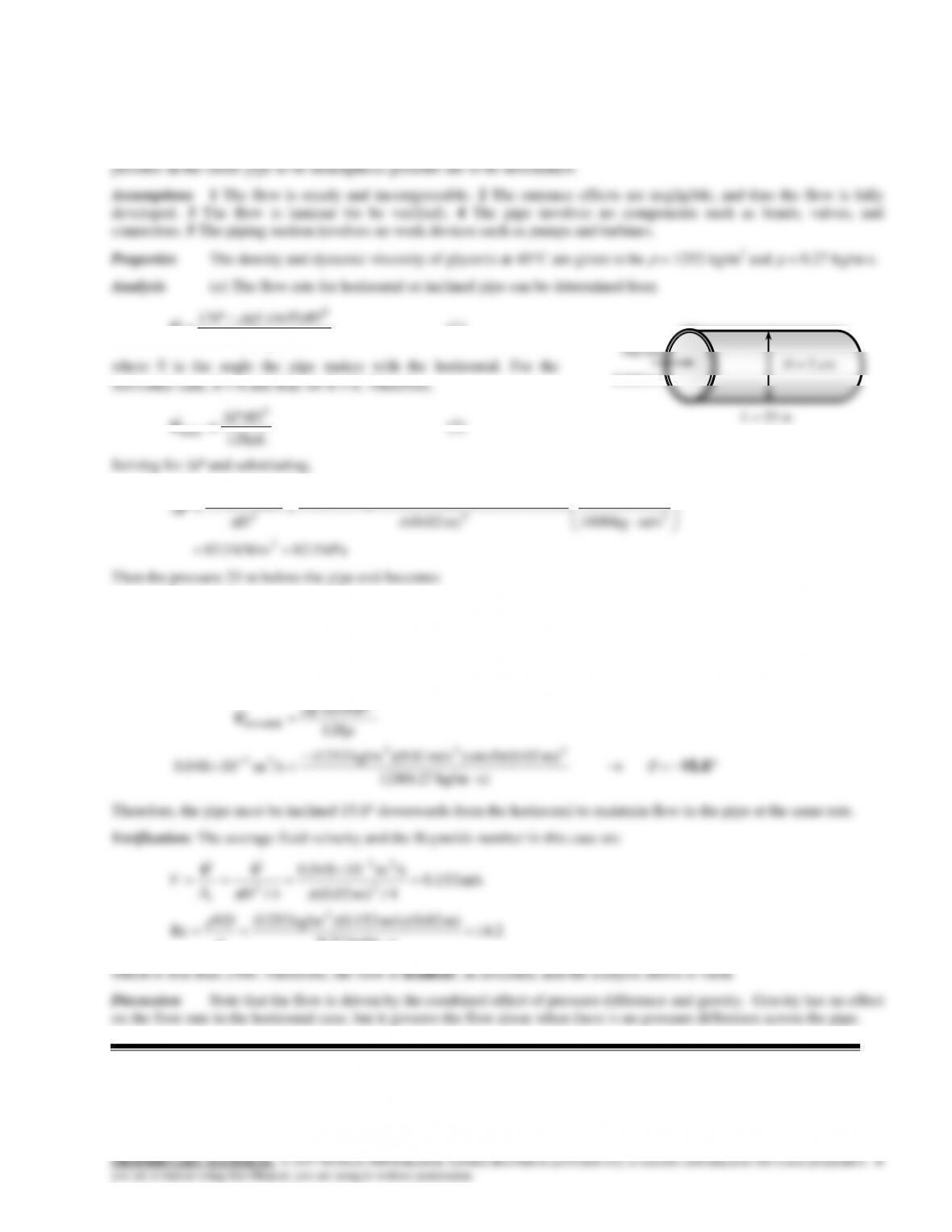
Solution Glycerin is flowing through a horizontal pipe which discharges into the atmosphere at a specified flow rate.
The absolute pressure at a specified location in the pipe, and the angle
that the pipe must be inclined downwards for the
L
DgLP
128
)sin( 4
V
(1)
Glycerin
14–43E
Solution Air is flowing through a square duct made of commercial steel at a specified rate. The pressure drop and
and
= 0.5718 ft2/s = 1.58810-4 ft2/s. The roughness of commercial steel surfaces is
= 0.00015 ft.
Analysis The hydraulic diameter, the average velocity, and the Reynolds number in this case are
ft 1
4
4
42
a
a
a
p
A
Dc
h
ft/s 26.67ft/min 1600
ft) (1
/minft 1600
2
3
2
a
A
V
c
VV
5
ft) ft/s)(1 (26.67
h
VD
Air duct
1 ft 1 ft
14-44
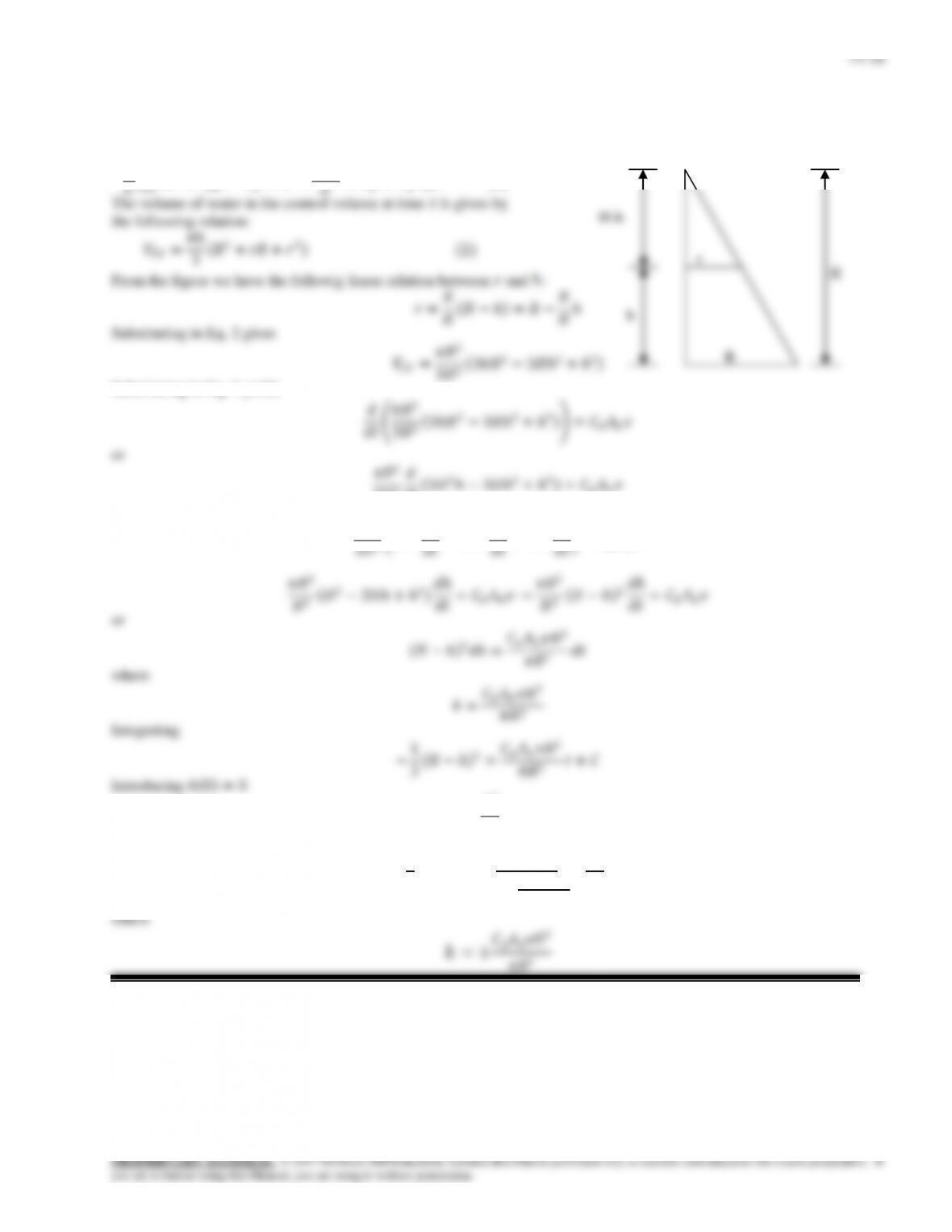
Solution Water enters into a cone through a small hole at the base. A relation for the variation of water height from
the cone base with time is to be obtained.
Analysis From the conservation of mass principle we write
𝑑
Substituting in Eq. 1 yields 𝑑
3𝐻2𝑑
𝑑𝑡 3𝐻2ℎ−3𝐻ℎ2+ℎ3 =𝐶𝑑𝐴ℎ𝑣
𝜋𝑅2
3=𝐶
Then we obtain −1
3 𝐻−ℎ 3=𝐶𝑑𝐴ℎ𝑣𝐻2
𝜋𝑅2𝑡−𝐻3
3
ℎ 𝑡 =𝐻− 𝐻3−𝑘𝑡
3
14–27
14-45
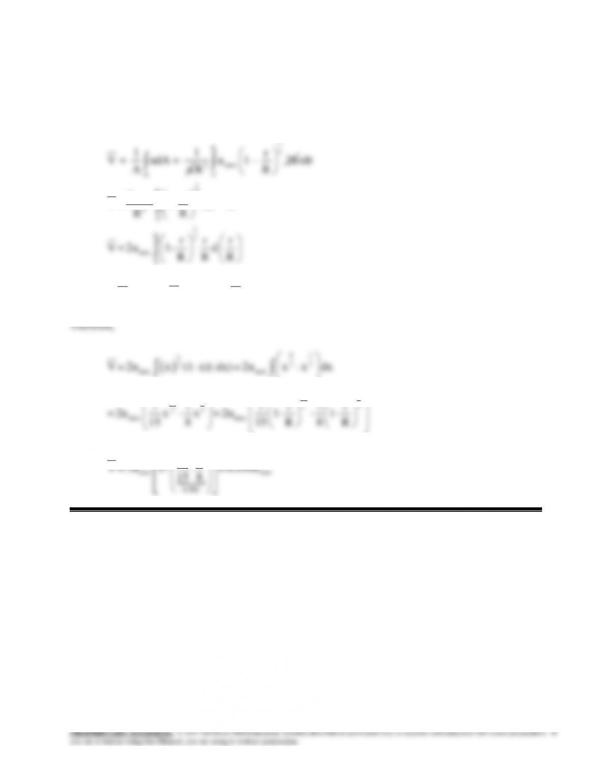
Solution The velocity profile for incompressible turbulent flow in a pipe is given. An expression for the average
velocity in the pipe is to be obtained.
Assumptions 1 The flow is steady and incompressible.
Analysis
A
11
V = udA =
Au
1
R7
max
2
0
r
u 1 – 2π
R
R
1
R7
max
2
0
1
R7
max
0
rdr
2u r
V = 1– rdr or
RR
r r r
V = 2u 1– d
R R R
Letting
r
1- = x
R
,
r
–d = dx
R
and
r=1- x
R
14–46
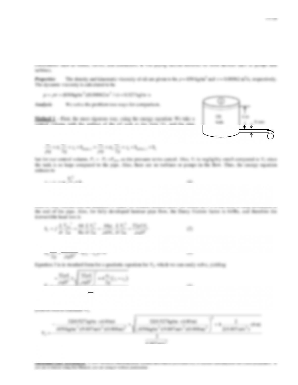
Solution Oil is being discharged by a horizontal pipe from a storage tank open to the atmosphere. The flow rate of oil
through the pipe is to be determined.
Assumptions 1 The flow is steady and incompressible. 2 The entrance effects are negligible, and thus the flow is fully
developed. 3 The entrance and exit loses are negligible. 4 The flow is laminar (to be verified). 5 The pipe involves no
control volume with the surface of the oil tank as the inlet (1), and the pipe
discharge as the outlet (2), as sketched. The energy equation in head form from 1
to 2 (see Chapter 5) is
22
1 1 2 2
22
P V P V
g g g g
but for our control volume, P1 = P2 =Patm, so the pressure terms cancel. Also, V1 is negligibly small compared to V2 since
the tank is so large compared to the pipe. Also, there are no turbines or pumps in the flow. Thus, the energy equation
reduces to
2
2
1 2 2 2L
V
z z h
g
(1)
The kinetic energy correction factor and the equation for the head loss term both depend on whether the flow in the pipe is
laminar or turbulent. We assume one or the other, and then verify at the end whether our assumption was correct. Since the
2
2
2 Re 2 2
D g D g DV D g gD
where we have also used the fact that V2 = Vavg. Combining Eqs. 1 and 2, we get
2
22
32 0
V LV zz
tank
8 mm
2
14–29
from which we calculate the volume flow rate,
2
14–30
14–47
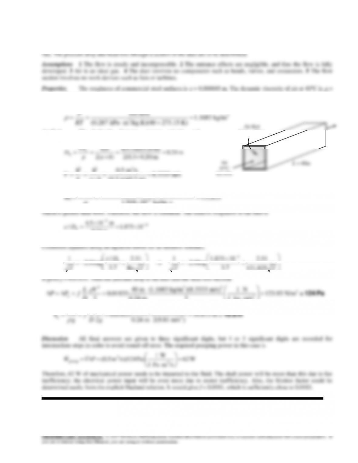
Solution Air in a heating system is distributed through a rectangular duct made of commercial steel at a specified
1.91810-5 kg/ms, and it is independent of pressure. The density of air listed in that table is for 1 atm. The density at 105
kPa and 315 K can be determined from the ideal gas relation to be
3
3
105 kPa 1.1683 kg/m
(0.287 kPa m /kg.K)(40 273.15 K)
P
RT
Analysis The hydraulic diameter, average velocity, and
Reynolds number are
m 24.0
m 0.20)2(0.3
m) m)(0.20 (0.34
)(2
4
4
ba
ab
p
A
Dc
h
3
0.5 m /s 8.3333 m/s
VV
Air
43C
L = 40m
Air duct
0.2 m 0.3 m
14–31
14–48
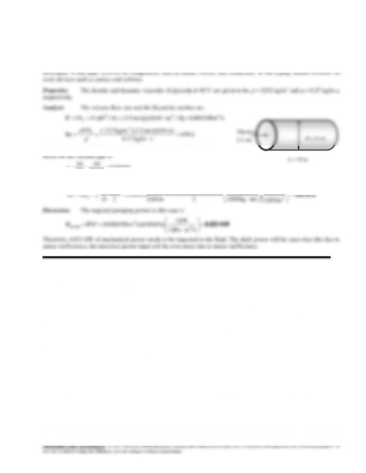
Solution Glycerin is flowing through a smooth pipe with a specified average velocity. The pressure drop per 10 m of
the pipe is to be determined.
Assumptions 1 The flow is steady and incompressible. 2 The entrance effects are negligible, and thus the flow is fully
skg/m 27.0
which is less than 2300. Therefore, the flow is laminar, and the friction
09859.0
2.649
64
Re
64 f
Then the pressure drop in the pipe becomes
23
2
kPa 1
kN 1
)m/s 5.3)(kg/m 1252(
m 10
V
L
L = 10 m
D = 4 cm
3.5 m/s
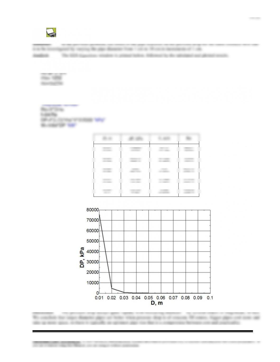
14–49
g=9.81
Vdot=3.5*pi*(0.05)^2/4
mu=0.27
L= 10
V=Vdot/Ac
14–33
14–50E
Solution The pressure readings across a pipe are given. The flow rates are to be determined for three different
orientations of horizontal, uphill, and downhill flow.
Assumptions 1 The flow is steady and incompressible. 2 The entrance effects are negligible, and thus the flow is fully
222
ft 001364.04/ft) 12/5.0(4/
DA
c
(a) The flow rate for all three cases can be determined from
L
DgLP
128
)sin( 4
V
psi 61.23
ft/slbm 2.32
lbf 1
lbf/ft 144
psi 1
20sin)ft 175)(ft/s 2.32)(lbm/ft 8.56(sin 22
23
gL
20
128
)sin(
4
uphill
L
DgLP
V
20
Oil
L = 175 ft
D = 0.5 in
14-51
Solution Liquid ammonia is flowing through a copper tube at a specified mass flow rate. The pressure drop, the head
loss, and the pumping power required to overcome the frictional losses in the tube are to be determined.
PROPRIETARY MATERIAL. © 2017 McGraw-Hill Education. Limited distribution permitted only to teachers and educators for course preparation. If
you are a student using this Manual, you are using it without permission.
14–52C
Solution We are to compare two different ways to reduce the minor loss in pipe bends.
14-53C
Solution We are to define equivalent length and its relationship to the minor loss coefficient.
f
Discussion Equivalent length is not as universal as minor loss coefficient because it depends on the roughness and
Reynolds number of the equivalent straight section of pipe.
14-54C
Solution We are to discuss the effect of rounding a pipe inlet.
Discussion In fact, the minor loss coefficient changes from 0.8 for a reentrant pipe inlet to about 0.03 for a well–
rounded pipe inlet – quite a significant improvement.
14–36
Discussion Note, however, that pressure is “recovered” in a gradual expansion. In other words, the pressure rises in the
direction of flow. Such a device is called a diffuser.
14–57C
Solution We are to define minor loss and minor loss coefficient.
14–58
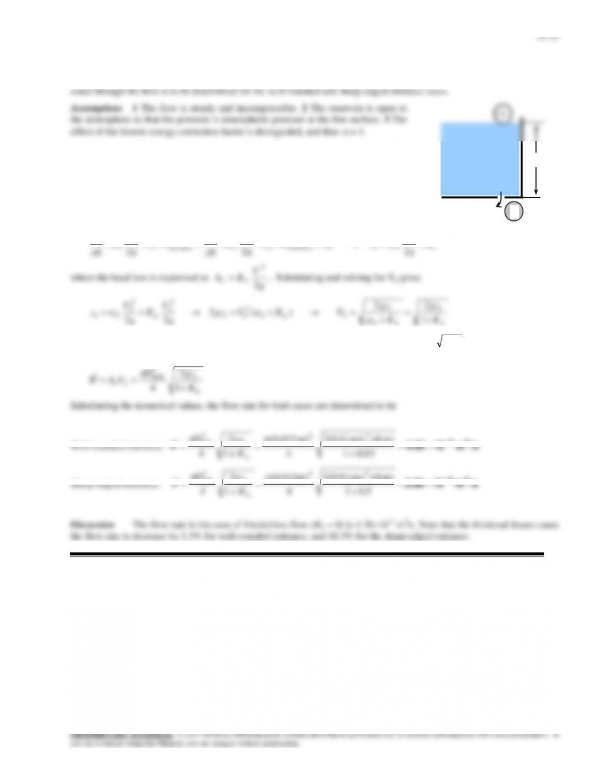
Solution Water is to be withdrawn from a water reservoir by drilling a hole at the bottom surface. The flow rate of
1
Analysis The loss coefficient is KL = 0.5 for the sharp-edged entrance, and KL
= 0.03 for the well-rounded entrance. We take point 1 at the free surface of the
reservoir and point 2 at the exit of the hole. We also take the reference level at the
exit of the hole (z2 = 0). Noting that the fluid at both points is open to the atmosphere
(and thus P1 = P2 = Patm) and that the fluid velocity at the free surface is zero (V1 =
0), the energy equation for a control volume between these two points (in terms of
heads) simplifies to
2
22
2
2
21e turbine,2
2
2
2
2
upump,1
2
1
1
1
LL h
g
V
zhhz
g
V
g
P
hz
g
V
g
P
where the head loss is expressed as
g
V
Kh LL 2
2
. Substituting and solving for V2 gives
LL
LL K
gz
K
gz
VKVgz
g
V
K
g
V
z
1
22
)(2
22
1
2
1
22
2
21
2
2
2
2
21
since
2 = 1. Note that in the special case of KL = 0, it reduces to the Toricelli equation
12 2gzV
, as expected. Then the
volume flow rate becomes
L
hole
cK
gz
D
VA
1
2
4
1
2
2
V
Substituting the numerical values, the flow rate for both cases are determined to be
m) 8)(m/s 81.9(2
)m 022.0(
2
22
1
2
hole
gz
D
8 m
Dhole= 2.2 cm
Water
2
14–38
14–59
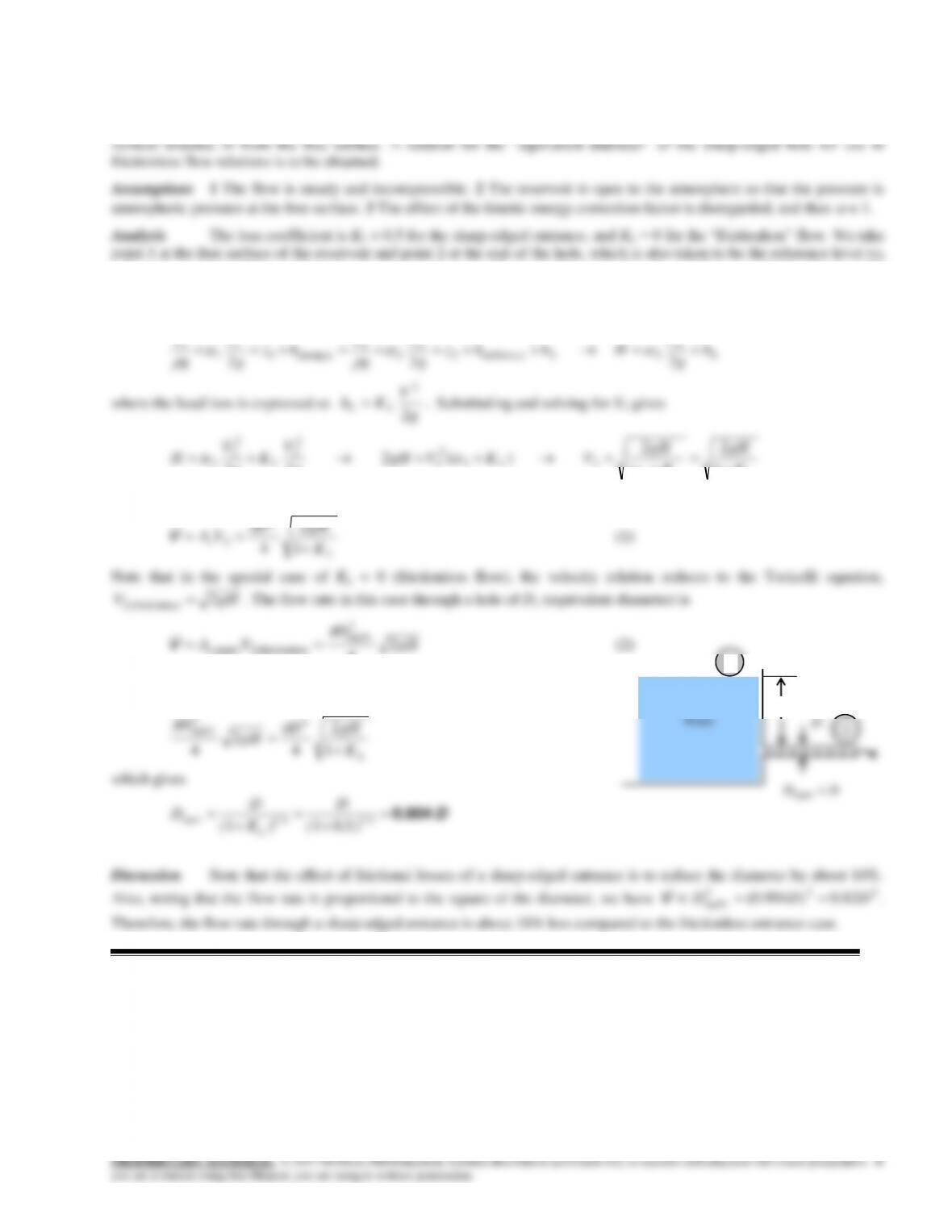
Solution Water is discharged from a water reservoir through a circular hole of diameter D at the side wall at a
= 0). Noting that the fluid at both points is open to the atmosphere (and thus P1 = P2 = Patm) and that the fluid velocity at the
free surface is zero (V1 = 0), the energy equation for a control volume between these two points (in terms of heads)
simplifies to
2
22
2
2
2e e, turbin2
2
2
2
2
upump,1
2
1
1
1
LL h
g
V
Hhhz
g
V
g
P
hz
g
V
g
P
where the head loss is expressed as
g
V
Kh LL 2
2
. Substituting and solving for V2 gives
LL
LL K
gH
K
gH
VKVgH
g
V
K
g
V
H
1
22
)(2
22 2
22
2
2
2
2
2
2
2
since
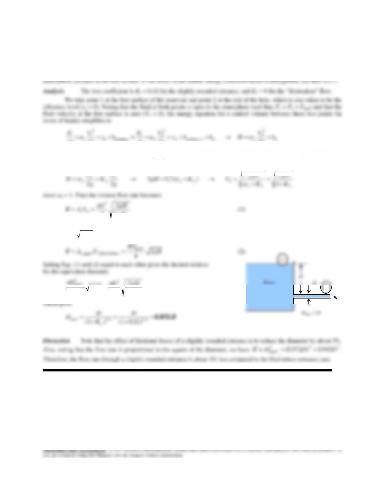
2 = 1. Then the volume flow rate becomes
L
cK
gH
D
VA
1
2
4
2
2
V
(1)
Note that in the special case of KL = 0 (frictionless flow), the velocity relation reduces to the Toricelli equation,
gHV2
ssfrictionle,2
. The flow rate in this case through a hole of De (equivalent diameter) is
gH
D
VAc2
4
2
equiv
ssfrictionle,2equiv,
V
(2)
Setting Eqs. (1) and (2) equal to each other gives the desired relation for the
equivalent diameter,
L
K
gH
D
gH
D
1
2
4
2
4
2
2
equiv
which gives
equiv 1 4 1 4
1 1 0 5
//
L
DD
D( K ) ( . )
0.904 D
Discussion Note that the effect of frictional losses of a sharp-edged entrance is to reduce the diameter by about 10%.
Also, noting that the flow rate is proportional to the square of the diameter, we have
222
equiv 82.0)904.0( DDD
V
.
Therefore, the flow rate through a sharp-edged entrance is about 18% less compared to the frictionless entrance case.
Dequiv < D
H
D
Water
1
2
14–39
14-60
Solution Water is discharged from a water reservoir through a circular hole of diameter D at the side wall at a
vertical distance H from the free surface. A relation for the “equivalent diameter” of the slightly rounded hole for use in
frictionless flow relations is to be obtained.
Assumptions 1 The flow is steady and incompressible. 2 The reservoir is open to the atmosphere so that the pressure is
14–40
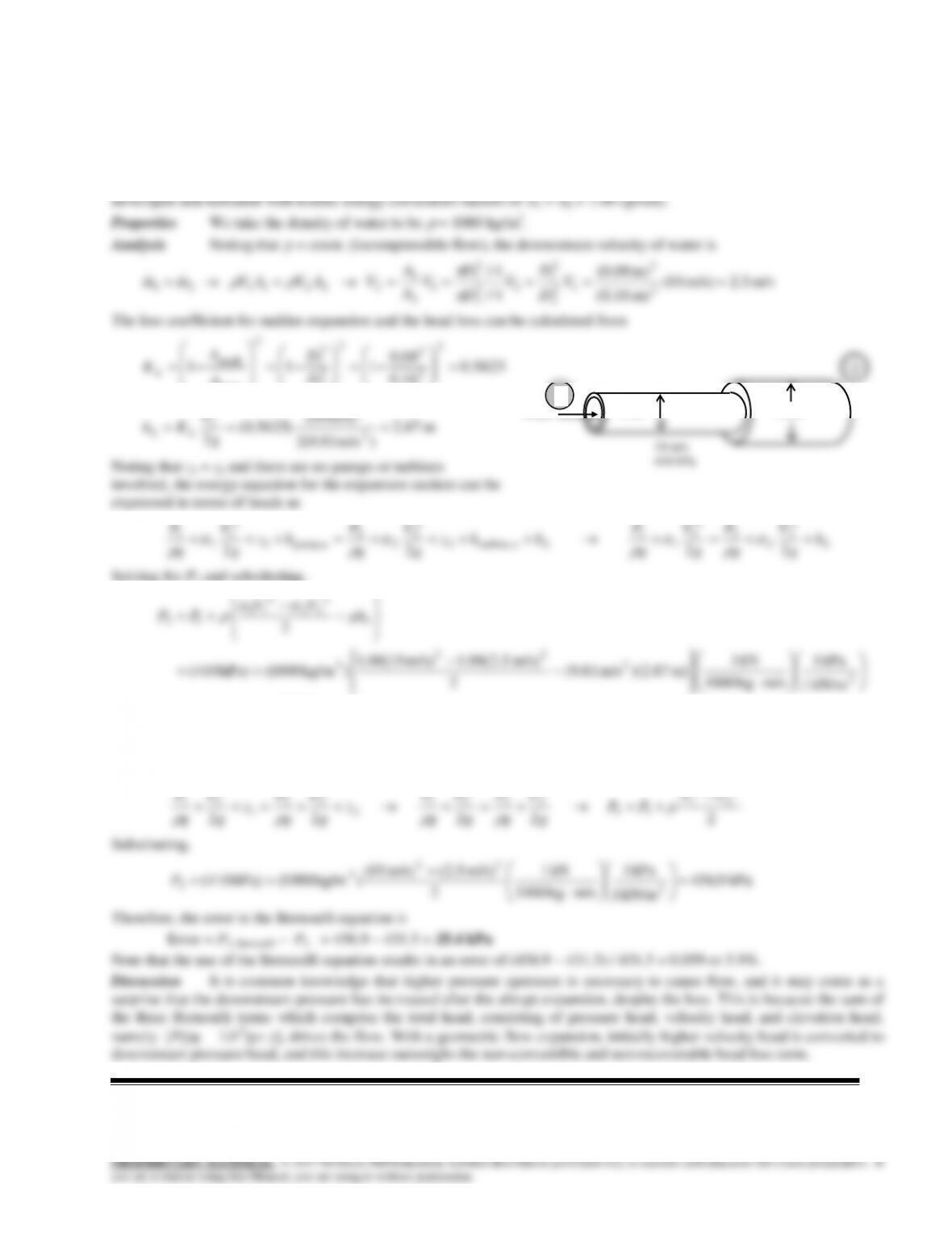
14-61
Solution A horizontal water pipe has an abrupt expansion. The water velocity and pressure in the smaller diameter
pipe are given. The pressure after the expansion and the error that would have occurred if the Bernoulli Equation had been
used are to be determined.
Assumptions 1 The flow is steady, horizontal, and incompressible. 2 The flow at both the inlet and the outlet is fully