Unlock document.
This document is partially blurred.
Unlock all pages and 1 million more documents.
Get Access
13-49
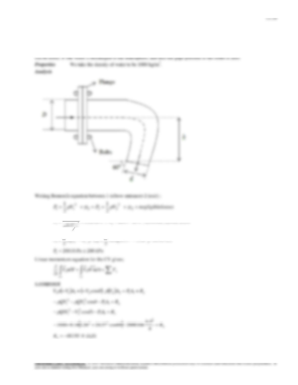
Solution Water is deflected by an elbow. The force acting on the flanges of the elbow and the angle its line of
action makes with the horizontal are to be determined by taking into consideration of the weight of the elbow.
Assumptions 1 The flow is steady and incompressible. 2 Frictional effects are negligible (so that the Bernoulli equation
2
smV /26.2
4
3.0
16.0
2
1
,
smV /37.20
2
, z1=0.5m , z2=0m ,P2=0
1
122
2
2
13-40
To include elbow weight we must modify y-momentum equation as follows:
y component:
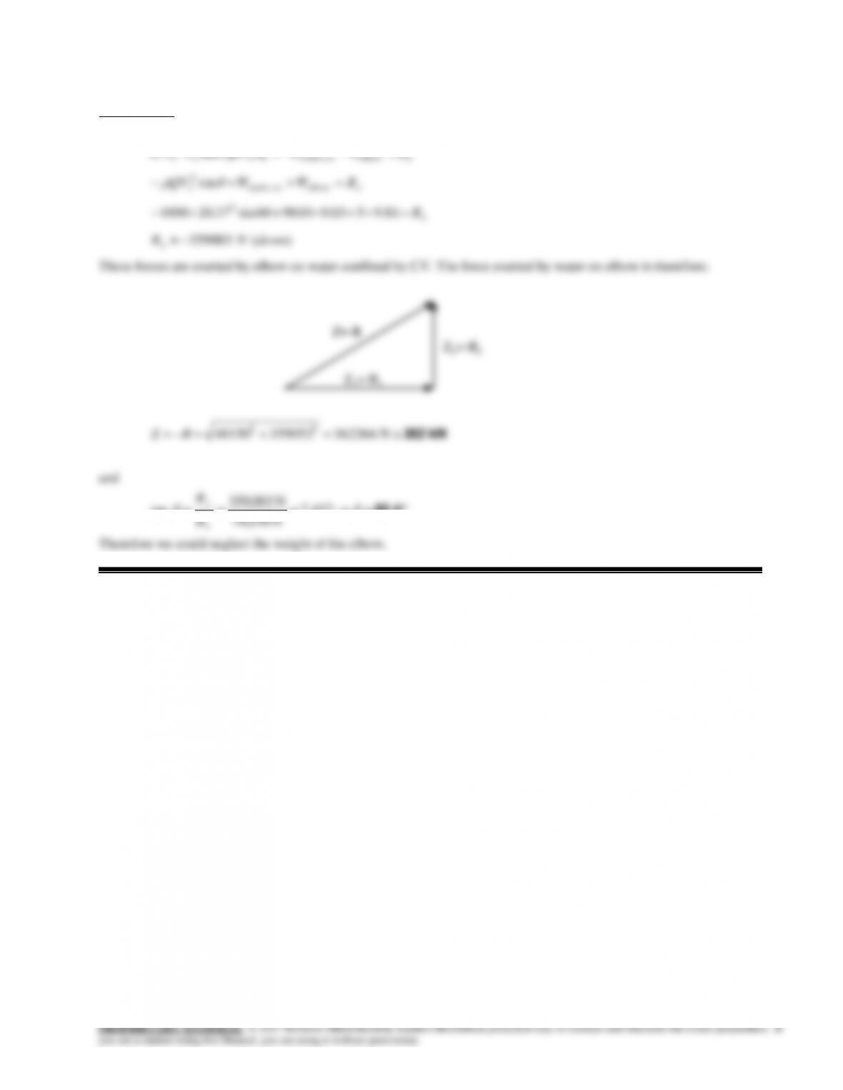
82.4
457.7
N 150,48
N 003,359
tan
x
y
R
R
13-41
13-50
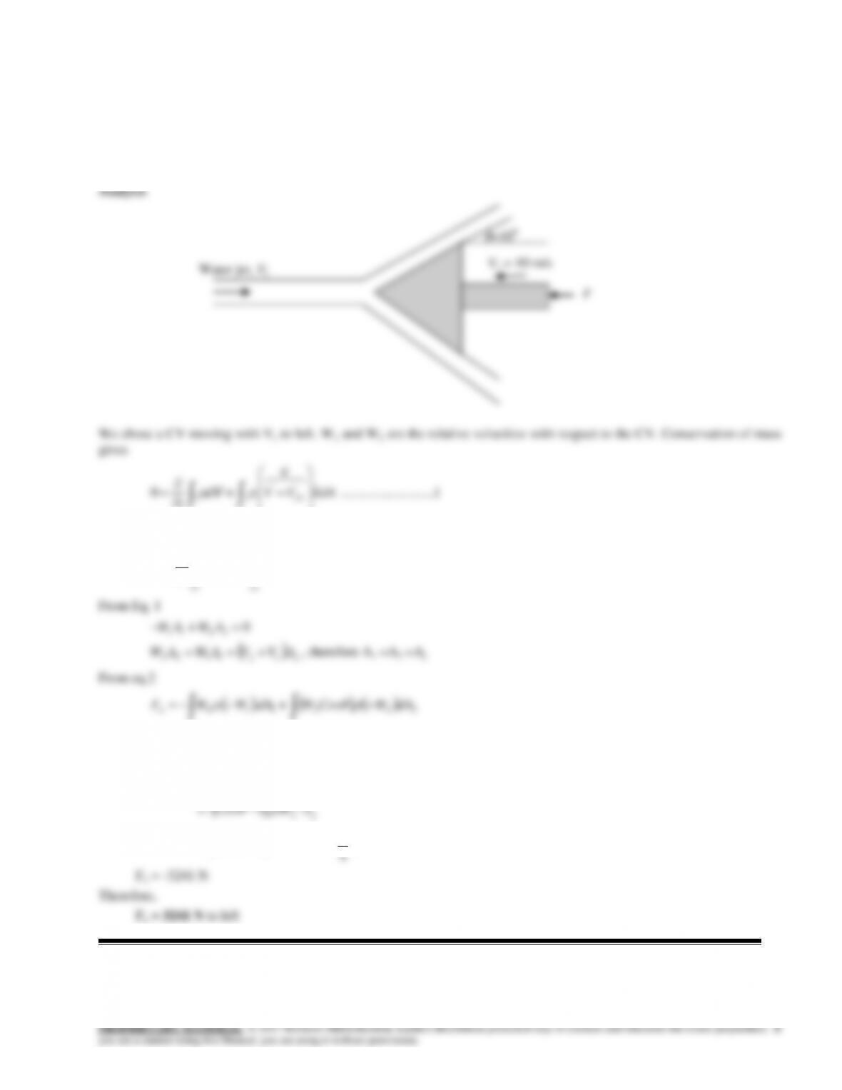
Solution A horizontal water jet is deflected by a cone. The external force needed to maintain the motion of the
cone is to be determined.
Assumptions 1 The flow is steady and incompressible. 2 The flow is uniform ine each section.
Properties We take the density of water to be 1000 kg/m3.
13-51
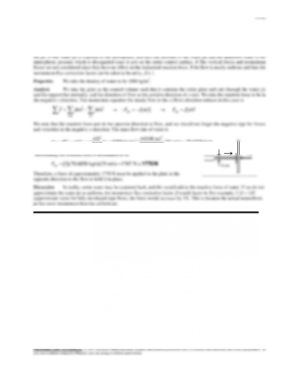
Solution A horizontal water jet strikes a vertical stationary flat plate normally at a specified velocity. For a given
flow velocity, the anchoring force needed to hold the plate in place is to be determined.
Assumptions 1 The flow is steady and incompressible. 2 The water splatters off the sides of the plate in a plane normal to
13-43
13-52
Solution Steady developing laminar flow is considered in a constant horizontal diameter discharge pipe. A relation is
1. 4 The momentum-flux correction factor is
= 2 at the outlet.
Analysis We take the developing flow section of the pipe (including the water inside) as the control volume. We
assume the reaction force to act in the positive direction. Noting that the flow is incompressible and thus the average
velocity is constant V1 = V2 = V, the momentum equation for steady flow in the z (flow) direction in this case reduces to
inout
VmVmF
VmVmAPAPF ccR 1221
VmDPP
VmAPP
VmAPPF
c
cR
4/)(
)21()(
)()(
2
21
21
2121
Or, using the definition of the mass flow rate,
222
21 ]4/[4/)( VDDPPFR
Or,
2
21
2
)(
4VPP
D
FR
Discussion Note that the cause of this reaction force is non-uniform velocity profile at the end.
13-53
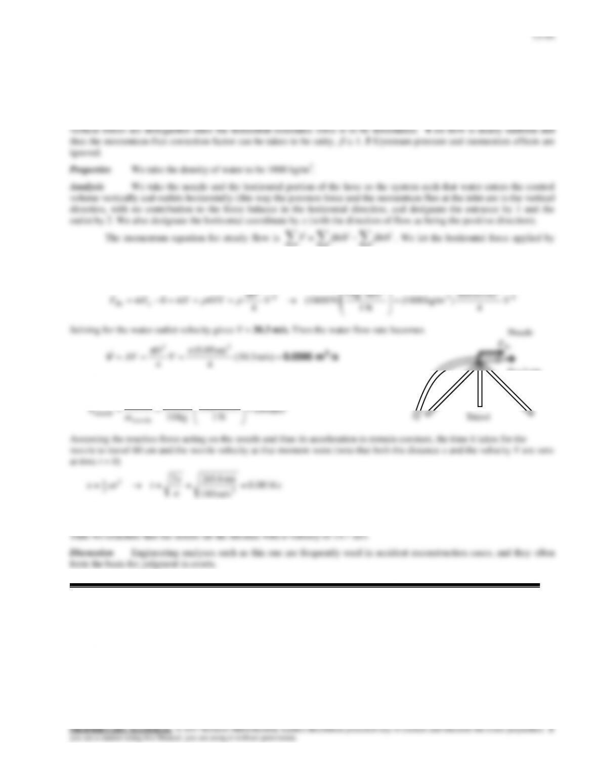
Solution A fireman was hit by a nozzle held by a tripod with a rated holding force. The accident is to be investigated
by calculating the water velocity, the flow rate, and the nozzle velocity.
Assumptions 1 The flow is steady and incompressible. 2 The water jet is exposed to the atmosphere, and thus the pressure
of the water jet is the atmospheric pressure, which is disregarded since it acts on all surfaces. 3 Gravitational effects and
13-45
13-54
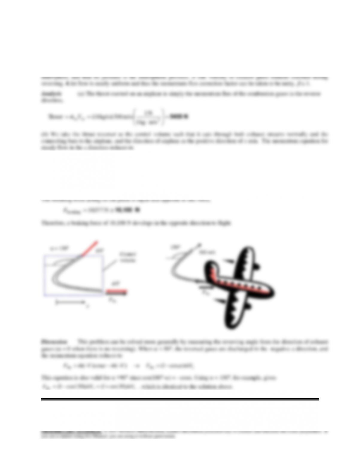
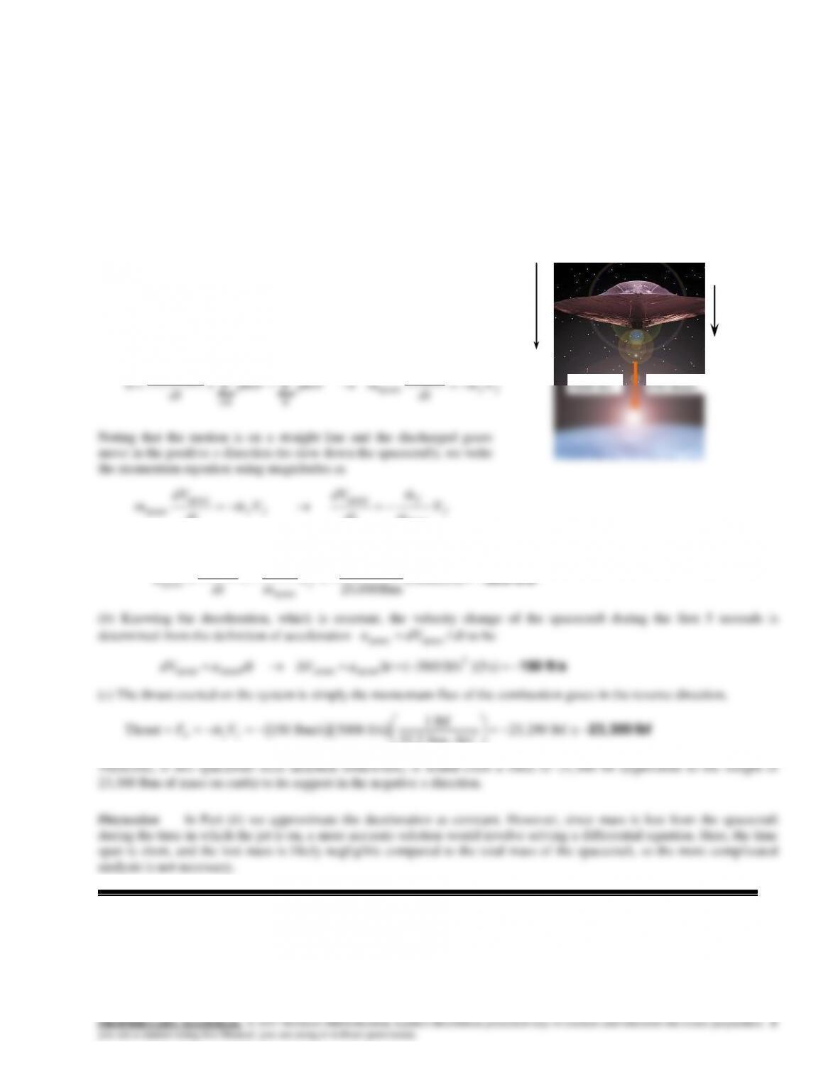
Solution During landing of an airplane, the thrust reverser is lowered in the path of the exhaust jet, which deflects the
exhaust and provides braking. The thrust of the engine and the braking force produced after the thrust reverser is deployed
are to be determined.
Assumptions 1 The flow of exhaust gases is steady and one-dimensional. 2 The exhaust gas stream is exposed to the
inout
VmVmF
)20cos1( )( )cos20( iRxRx VmFVmVmF
Substituting, the reaction force is determined to be
N 077,10m/s) kg/s)(300 18)(30cos1(
Rx
F
13-55
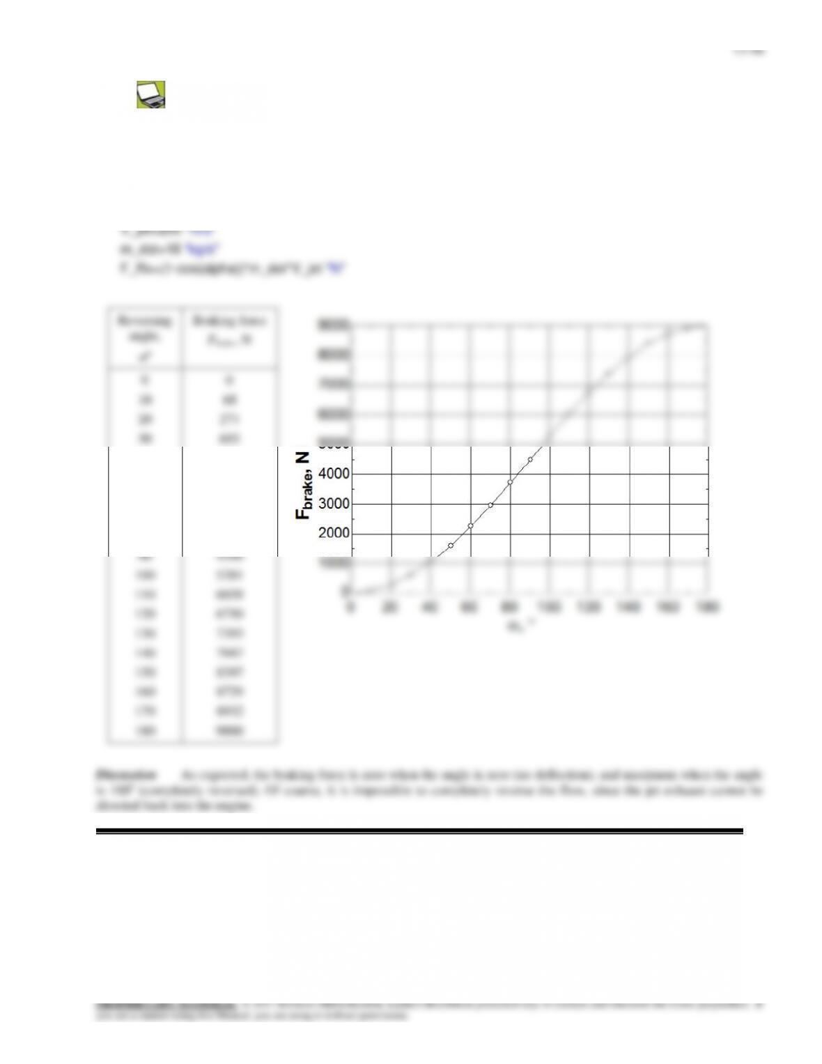
Solution The previous problem is reconsidered. The effect of thrust reverser angle on the braking force exerted on
the airplane as the reverser angle varies from 0 (no reversing) to 180 (full reversing) in increments of 10 is to be
investigated.
Analysis The EES Equations window is printed below, followed by the tabulated and plotted results.
Discussion As expected, the braking force is zero when the angle is zero (no deflection), and maximum when the angle
is 180o (completely reversed). Of course, it is impossible to completely reverse the flow, since the jet exhaust cannot be
directed back into the engine.
13-47
13-56E
Solution The rocket of a spacecraft is fired in the opposite direction to motion. The deceleration, the velocity change,
and the thrust are to be determined.
Assumptions 1 The flow of combustion gases is steady and one-dimensional during the firing period, but the flight of the
spacecraft is unsteady. 2 There are no external forces acting on the spacecraft, and the effect of pressure force at the nozzle
outlet is negligible. 3 The mass of discharged fuel is negligible relative to the mass of the spacecraft, and thus the spacecraft
may be treated as a solid body with a constant mass. 4 The nozzle is well-designed such that the effect of the momentum-
flux correction factor is negligible, and thus
1.
Analysis (a) We choose a reference frame in which the control
volume moves with the spacecraft. Then the velocities of fluid steams
become simply their relative velocities (relative to the moving body).
We take the direction of motion of the spacecraft as the positive
direction along the x axis. There are no external forces acting on the
spacecraft, and its mass is nearly constant. Therefore, the spacecraft can
be treated as a solid body with constant mass, and the momentum
equation in this case is
ff
CV Vm
dt
Vd
mVmVm
dt
Vmd
space
space
inout
)(
0
Noting that the motion is on a straight line and the discharged gases
move in the positive x direction (to slow down the spacecraft), we write
the momentum equation using magnitudes as
f
f
ff V
m
m
dt
dV
Vm
dt
dV
m
space
spacespace
space
Substituting, the deceleration of the spacecraft during the first 5 seconds is determined to be
lbm/s 150
space
fV
m
dV
2000 ft/s
25,000 lbm
150 lbm/s
5000 ft/s
x
13-57
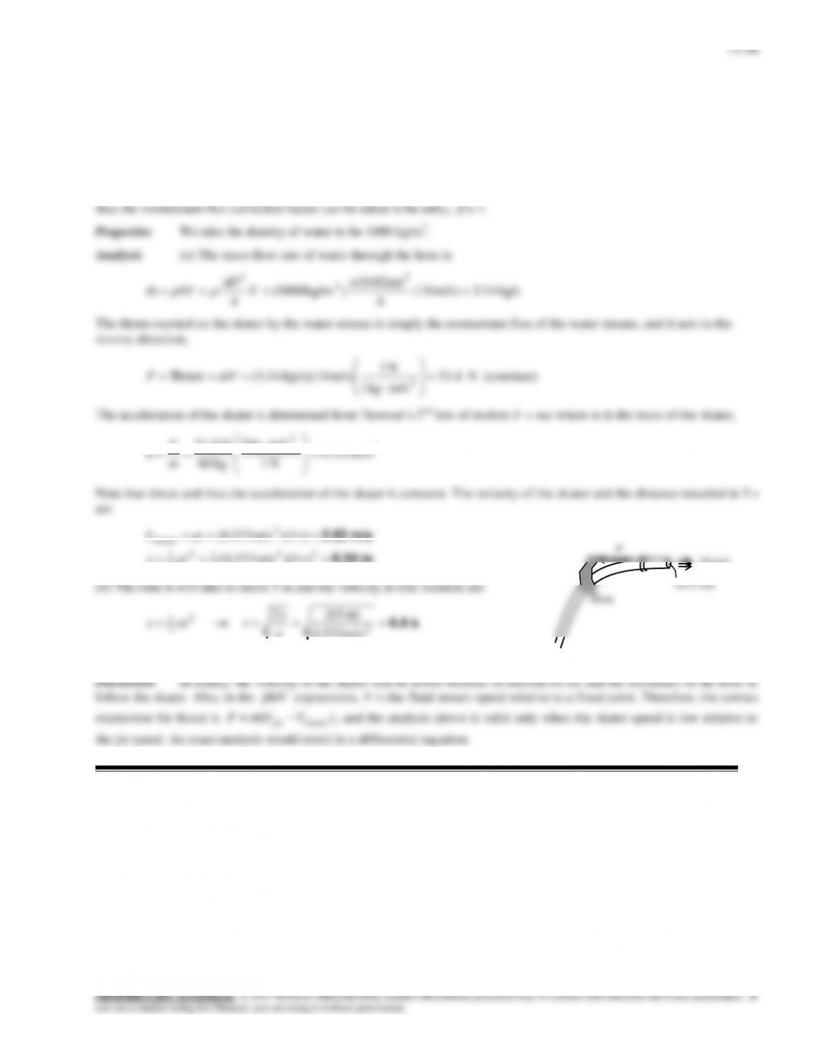
Solution An ice skater is holding a flexible hose (essentially weightless) which directs a stream of water horizontally
at a specified velocity. The velocity and the distance traveled in 5 seconds, and the time it takes to move 5 m and the
velocity at that moment are to be determined.
Assumptions 1 Friction between the skates and ice is negligible. 2 The flow of water is steady and one-dimensional (but
the motion of skater is unsteady). 3 The ice skating arena is level, and the water jet is discharged horizontally. 4 The mass
of the hose and the water in it is negligible. 5 The skater is standing still initially at t = 0. 6 Jet flow is nearly uniform and
2
2
m/s 0.523
N 1
m/skg 1
kg 60
N 4.31
m
F
a
Note that thrust and thus the acceleration of the skater is constant. The velocity of the skater and the distance traveled in 5 s
are
m/s 2.62
2
skater
s) 5)(m/s 0.523(
atV
m/s 2.3
s 4.4
s) 4.4)(m/s 0.523(
m/s 0.523
m) 5(2
2
2
skater
2
2
2
1
atV
a
x
tatx
Hose
13-58
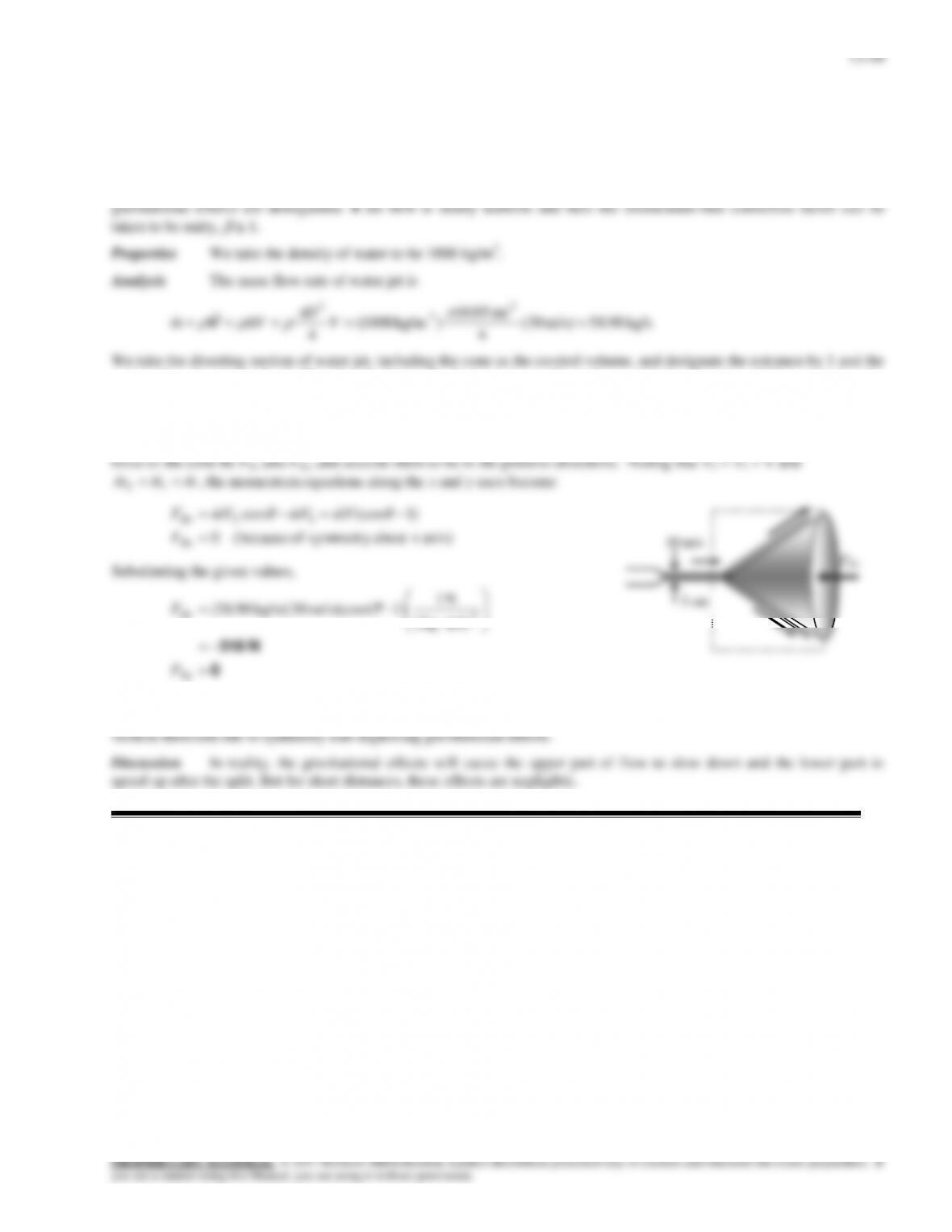
Solution A water jet hits a stationary cone, such that the flow is diverted equally in all directions at 45. The force
required to hold the cone in place against the water stream is to be determined.
Assumptions 1 The flow is steady and incompressible. 2 The water jet is exposed to the atmosphere, and thus the pressure
of the water jet before and after the split is the atmospheric pressure which is disregarded since it acts on all surfaces. 3 The
outlet after divergence by 2. We also designate the horizontal coordinate by x with the direction of flow as being the
positive direction and the vertical coordinate by y.
The momentum equation for steady flow is
inout
VmVmF
. We let the x- and y- components of the anchoring
13-50
13-59
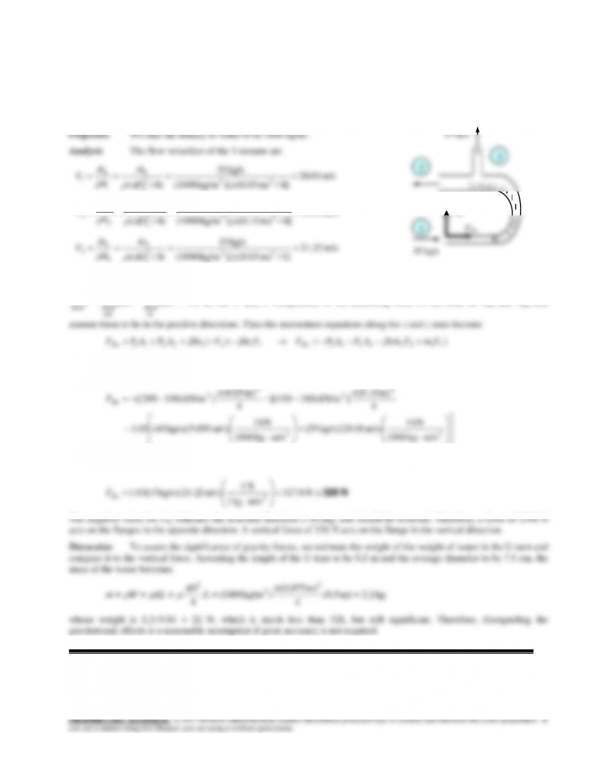
Solution Water is flowing into and discharging from a pipe U-section with a secondary discharge section normal to
return flow. Net x- and z- forces at the two flanges that connect the pipes are to be determined.
Assumptions 1 The flow is steady and incompressible. 2 The weight of the U-turn and the water in it is negligible. 4 The
momentum-flux correction factor for each inlet and outlet is given to be
= 1.03.
]4/m) 05.0()[kg/m (1000
)4/( 232
1
1
D
A
m/s 093.5
]4/m) 10.0()[kg/m (1000
kg/s 40
)4/( 232
2
2
2
2
2
D
m
A
m
V
]4/m) 03.0()[kg/m (1000
kg/s 15
)4/( 232
3
3
3
3
D
m
A
m
We take the entire U-section as the control volume. We designate the horizontal coordinate by x with the direction of
incoming flow as being the positive direction and the vertical coordinate by z. The momentum equation for steady flow is
inout
VmVmF
. We let the x- and z- components of the anchoring force of the cone be FRx and FRz, and
0-0
)( )(
3333
1122221111222211
VmFVmF
VmVmAPAPFVmVmAPAPF
RzRz
RxRx
Substituting the given values,
N 2390
kN 386.2
m/skg 1000
kN 1
m/s) 1kg/s)(28.0 55(
m/skg 1000
kN 1
m/s) 3kg/s)(5.09 40(03.1
4
m) (0.10
]kN/m )100150[(
4
m) (0.05
]kN/m )100200[(
22
2
2
2
2
Rx
F
N 328
N .8327
m/skg 1
N 1
m/s) 2kg/s)(21.2 15(03.1 2
Rz
F
The negative value for FRx indicates the assumed direction is wrong, and should be reversed. Therefore, a force of 2390 N
acts on the flanges in the opposite direction. A vertical force of 328 N acts on the flange in the vertical direction.
Discussion To assess the significance of gravity forces, we estimate the weight of the weight of water in the U-turn and
compare it to the vertical force. Assuming the length of the U-turn to be 0.5 m and the average diameter to be 7.5 cm, the
mass of the water becomes
kg2.2m) (0.5
4
m) (0.075
) kg/m1000(
4
2
3
2
L
D
ALm
V
whose weight is 2.29.81 = 22 N, which is much less than 328, but still significant. Therefore, disregarding the
gravitational effects is a reasonable assumption if great accuracy is not required.
1
40 kg/s
55 kg/s
FRz
FRx
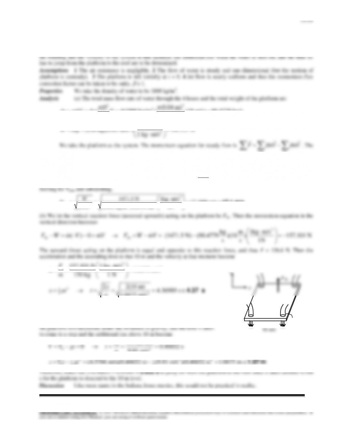
13-60
Solution Indiana Jones is to ascend a building by building a platform, and mounting four water nozzles pointing
down at each corner. The minimum water jet velocity needed to raise the system, the time it will take to rise to the top of
13-61E
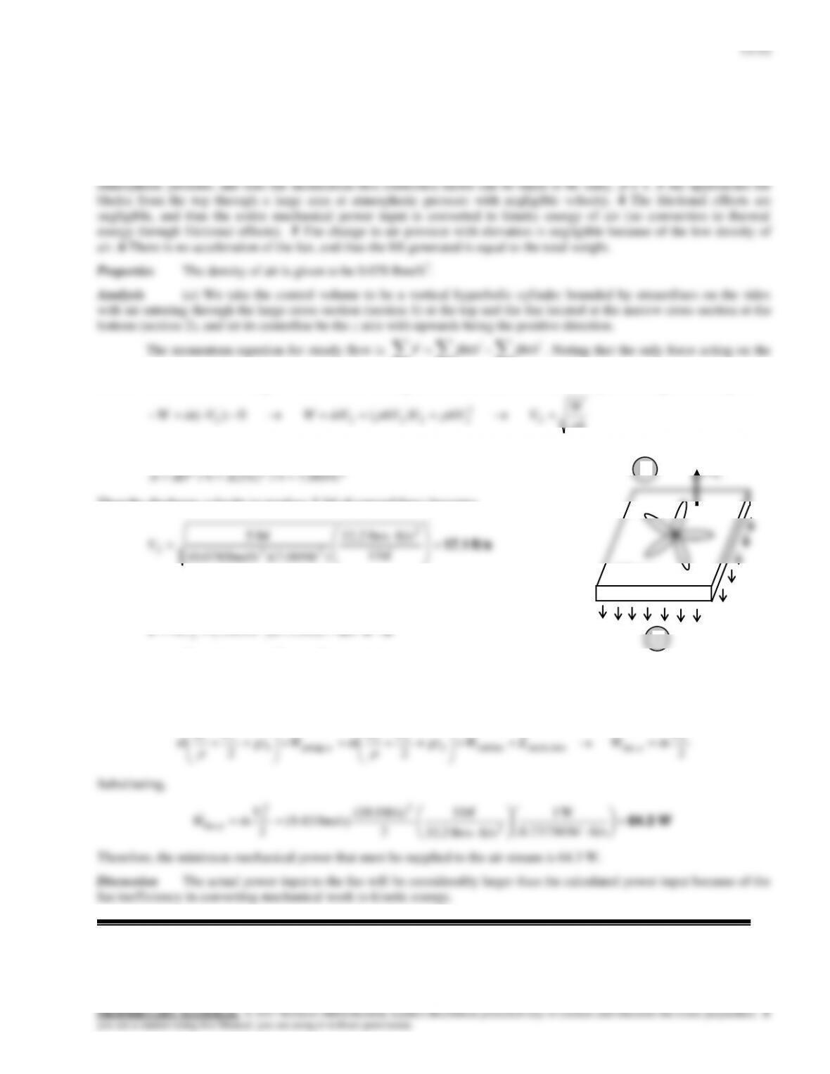
Solution A box-enclosed fan is faced down so the air blast is directed downwards, and it is to be hovered by
increasing the blade rpm. The required blade rpm, air outlet velocity, the volumetric flow rate, and the minimum
mechanical power are to be determined.
Assumptions 1 The flow of air is steady and incompressible. 2 The air leaves the blades at a uniform velocity at
inout
control volume is the total weight W and it acts in the negative z direction, the momentum equation along the z axis gives
)( 0)( 2
2
22222 A
W
VAVVAVVmWVmW
where A is the blade span area,
222 ft 069.74/ft) 3(4/
DA
Then the discharge velocity to produce 5 lbf of upward force becomes
ft/s 17.1
lbf 1
ft/slbm 32.2
)ft )(7.069lbm/ft (0.078
lbf 5 2
23
2
V
(b) The volume flow rate and the mass flow rate of air are determined from their
definitions,
/sft 121 3
ft/s) 1.17)(ft 069.7( 2
2
AV
V
lbm/s 43.9/s)ft 121)(lbm/ft 078.0( 33
V
m
(c) Noting that P1 = P2 = Patm, V1 0, the elevation effects are negligible, and the frictional effects are disregarded, the
energy equation for the selected control volume reduces to
lossmech,turbine2
2
22
upump,1
2
11
22 EWgz
VP
mWgz
VP
m
2
2
2
ufan,
V
mW
Substituting,
W64.3
ft/slbf 0.73756
W 1
ft/slbm 2.32
lbf 1
2
ft/s) (18.0
lbm/s) 43.9(
22
2
2
2
ufan,
V
mW
Therefore, the minimum mechanical power that must be supplied to the air stream is 64.3 W.
Discussion The actual power input to the fan will be considerably larger than the calculated power input because of the
fan inefficiency in converting mechanical work to kinetic energy.
600 rpm
FRy
1
2
13-53
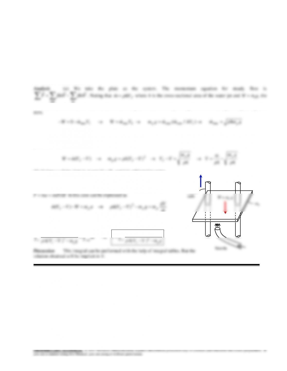
13-62
Solution A plate is maintained in a horizontal position by frictionless vertical guide rails. The underside of the plate
is subjected to a water jet. The minimum mass flow rate
min
m
to just levitate the plate is to be determined, and a relation is
to be obtained for the steady state upward velocity. Also, the integral that relates velocity to time when the water is first
turned on is to be obtained.
Assumptions 1 The flow of water is steady and one-dimensional. 2 The water jet splatters in the plane of he plate. 3 The
vertical guide rails are frictionless. 4 Times are short, so the velocity of the rising jet can be considered to remain constant
with height. 5 At time t = 0, the plate is at rest. 6 Jet flow is nearly uniform and thus the momentum-flux correction factor
can be taken to be unity,
1.
inout
J
minimum mass flow rate of water needed to raise the plate is determined by setting the net force acting on the plate equal to
For
min
mm
, a relation for the steady state upward velocity V is obtained setting the upward impulse applied by water jet
to the weight of the plate (during steady motion, the plate velocity V is constant, and the velocity of water jet relative to
plate is VJ –V),
A
gm
A
m
V
A
gm
VVVVAgmVVmW pp
JJpJ
)( )( 2
(b) At time t = 0 the plate is at rest (V = 0), and it is subjected to water
jet with
min
mm
and thus the net force acting on it is greater than the
weight of the plate, and the difference between the jet impulse and the
weight will accelerate the plate upwards. Therefore, Newton’s 2nd law
dt
dV
mgmVVAamWVVm ppJpJ 2
)( )(
Separating the variables and integrating from t = 0 when V = 0 to t = t
when V = V gives the desired integral,
V
2
0 0
t
p
t
Jp
m dV dt
A(V V ) m g
V
2
0
p
Jp
m dV
tA(V V ) m g
Discussion This integral can be performed with the help of integral tables. But the
relation obtained will be implicit in V.
mp
Guide
m
Nozzle
FRz
W = mp g
.
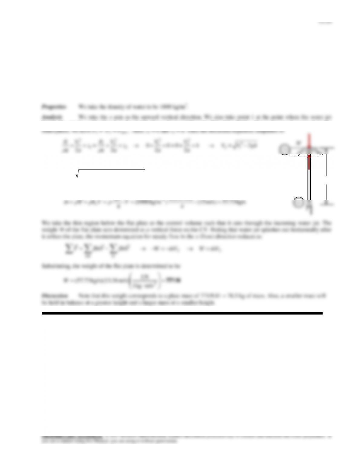
13-63
Solution A vertical water jet strikes a horizontal stationary plate normally. The maximum weight of the plate that can
be supported by the water jet at a specified height is to be determined.
Assumptions 1 The flow of water at the nozzle outlet is steady and incompressible. 2 The water splatters in directions
normal to the approach direction of the water jet. 3 The water jet is exposed to the atmosphere, and thus the pressure of the
water jet and the splattered water leaving the control volume is atmospheric pressure . 4 Friction between the water and air
is negligible. 5 The effect of the momentum-flux correction factor is negligible, and thus
1 for the jet.
leaves the nozzle, and point 2 at the point where the jet strikes the flat plate. Noting that water jet is exposed to the
g
g
g
g
g
g
2
2
22
12
2
1
Substituting, the jet velocity when the jet strikes the flat plate is determined to be
m/s 63.13)m 2)(m/s 81.9(2)m/s 15(22
2
V
The mass flow rate of water is
kg/s73.57m/s) (15
4
m) (0.07
) kg/m1000(
4
2
3
2
V
D
VAm c
V
We take the thin region below the flat plate as the control volume such that it cuts through the incoming water jet. The
weight W of the flat plate acts downward as a vertical force on the CV. Noting that water jet splashes out horizontally after
it strikes the plate, the momentum equation for steady flow in the x (flow) direction reduces to
inout
VmVmF
22 VmWVmW
Substituting, the weight of the flat plate is determined to be
N 771
2
m/s kg1
N 1
m/s) 36 kg/s)(13.73.57(W
Discussion Note that this weight corresponds to a plate mass of 771/9.81 = 78.5 kg of mass. Also, a smaller mass will
be held in balance at a greater height and a larger mass at a smaller height.
V2
h
1
2
13-55
13-64
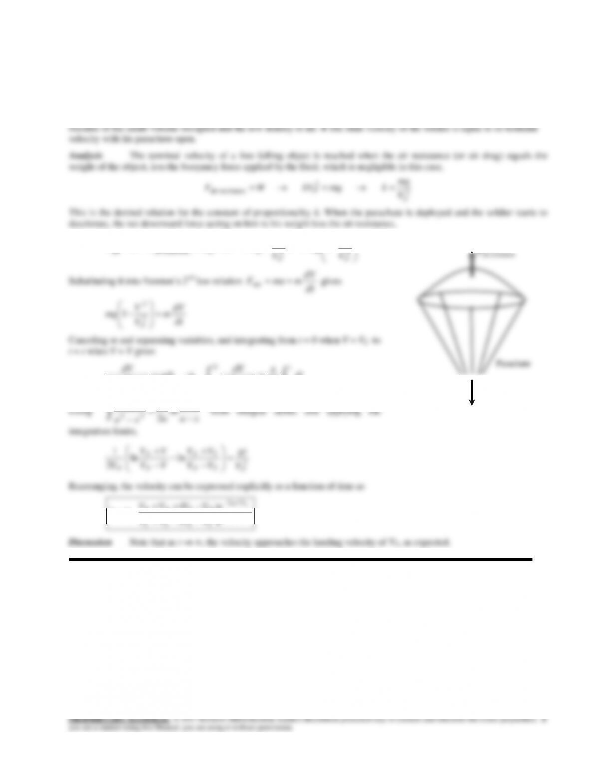
Solution A parachute slows a soldier from his terminal velocity VT to his landing velocity of VF. A relation is to be
developed for the soldier’s velocity after he opens the parachute at time t = 0.
Assumptions 1 The air resistance is proportional to the velocity squared (i.e. F = -kV2). 2 The variation of the air
properties with altitude is negligible. 3 The buoyancy force applied by air to the person (and the parachute) is negligible
2
2
2
2
2
anceair resistnet 1
FF V
V
mgV
V
mg
mgkVmgFWF
dV
gdt
VV
dV
F
22 /1
dt
V
g
VV
dV t
FF
T
0
2
V
V 22
xa
dx
1
Parachute
Fair resistance
W = mg
PROPRIETARY MATERIAL. © 2017 McGraw-Hill Education. Limited distribution permitted only to teachers and educators for course preparation. If
you are a student using this Manual, you are using it without permission.
13-65


