13-32E
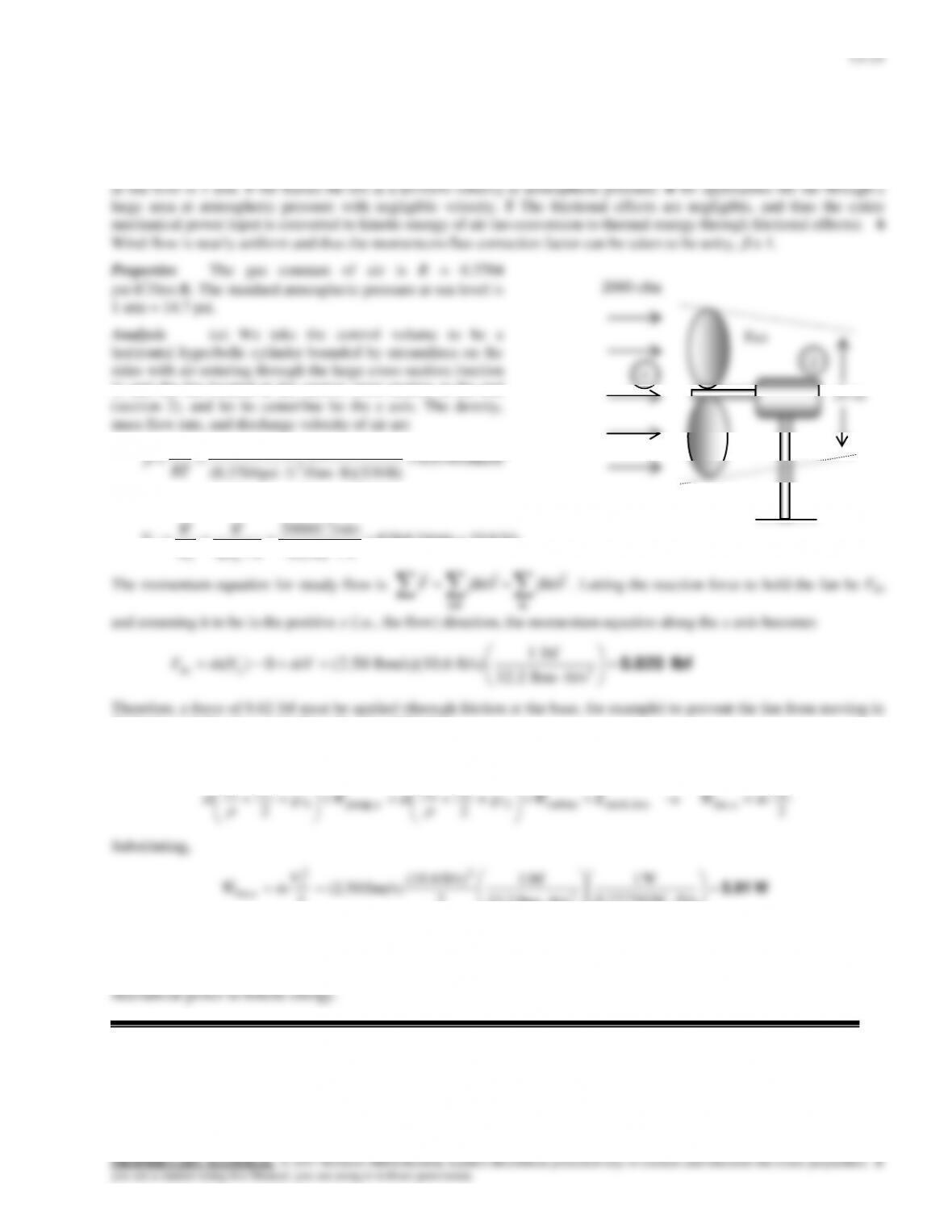
Solution A fan moves air at sea level at a specified rate. The force required to hold the fan and the minimum power
input required for the fan are to be determined.
Assumptions 1 The flow of air is steady and incompressible. 2 Standard atmospheric conditions exist so that the pressure
2
1) and the fan located at the narrow cross-section at the end
3
3lbm/ft 0749.0
R) R)(530/lbmftpsi (0.3704
psi 7.14
RT
P
lbm/s 2.50lbm/min 8.149/min)ft 2000)(lbm/ft 0749.0( 33
V
m
ft/s 10.6ft/min 6.636
4/ft) 2(
/minft 2000
4/ 2
3
2
2
2
2
D
A
V
VV
the horizontal direction under the influence of this force.
(b) Noting that P1 = P2 = Patm and V1 0, the energy equation for the selected control volume reduces to
lossmech,turbine2
2
22
upump ,1
2
11
22 EWgz
VP
mWgz
VP
m
2
2
2
ufan,
V
mW
Substituting,
W 5.91
ft/slbf 0.73756
W1
ft/slbm 2.32
lbf 1
2
ft/s) (10.6
lbm/s) 50.2(
22
2
2
2
ufan,
V
mW
Therefore, a useful mechanical power of 5.91 W must be supplied to air. This is the minimum required power input required
for the fan.
Discussion The actual power input to the fan will be larger than 5.91 W because of the fan inefficiency in converting
24 in
1
13–22
13-33E
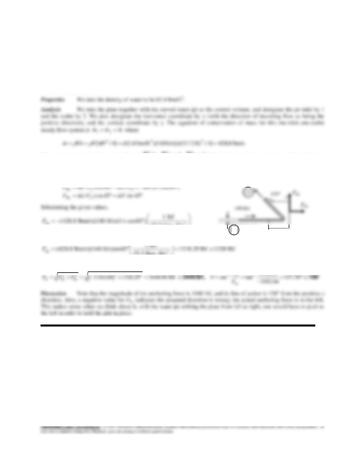
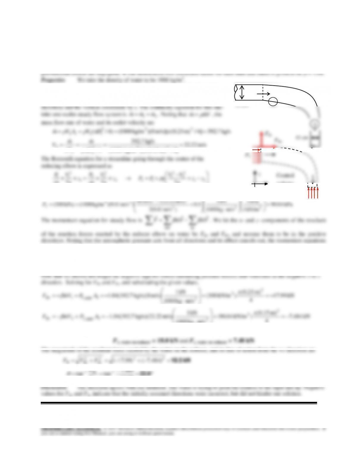
Solution A horizontal water jet strikes a bent plate, which deflects the water by 135 from its original direction. The
force required to hold the plate against the water stream is to be determined.
Assumptions 1 The flow is steady and incompressible. 2 The water jet is exposed to the atmosphere, and thus the pressure
of the water jet and the splattered water is the atmospheric pressure, which is disregarded since it acts on all surfaces. 3
Frictional and gravitational effects are negligible. 4 There is no splattering of water or the deformation of the jet, and the
reversed jet leaves at the same velocity and flow rate. 5 Jet flow is nearly uniform and thus the momentum-flux correction
factor is nearly unity,
1.
The momentum equation for steady flow is
inout
VmVmF
. We let the x- and z- components of the anchoring
force of the plate be FRx and FRz, and assume them to be in the positive directions. Then the momentum equations along the
x and y axes become
45sin45sin)(
)45cos1()(45cos)(
2
12
VmVmF
VmVmVmF
Rz
Rx
Substituting the given values,
2
1 lbf
(428.8 lbm/s)(140 ft/s)(1 cos45 ) 32.2 lbm ft/s
3182.64 lbf 3180 lbf
Rx
F
2
1 lbf
32.2 lbm ft/s
Rz
and
2
2 2 2 -1 1 1318 29
3182 64 1318 29 3444 86 lbf tan tan 157 50
3182 64
Ry –
R Rx Rz
Rx
F.
F F F . . . .
F.
,3440 lbf 158
Discussion Note that the magnitude of the anchoring force is 3440 lbf, and its line of action is 158 from the positive x
direction. Also, a negative value for FRx indicates the assumed direction is wrong; the actual anchoring force is to the left.
This makes sense when we think about it; with the water jet striking the plate from left to right, one would have to push to
the left in order to hold the plat in place.
140 ft/s
Waterjet
135
3 in
2
1
FRz
FRx
13-34
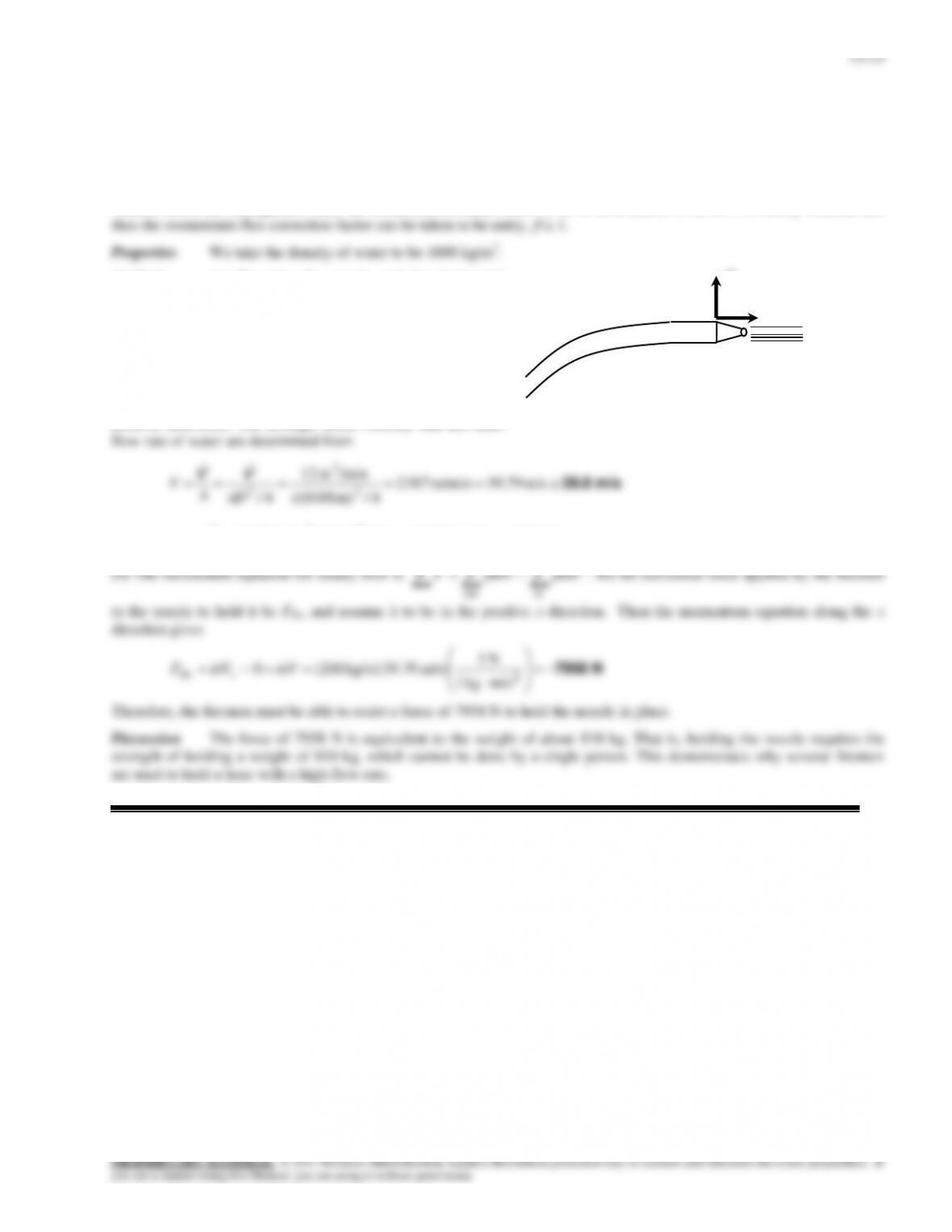
Solution Firemen are holding a nozzle at the end of a hose while trying to extinguish a fire. The average water outlet
velocity and the resistance force required of the firemen to hold the nozzle are to be determined.
Assumptions 1 The flow is steady and incompressible. 2 The water jet is exposed to the atmosphere, and thus the pressure
of the water jet is the atmospheric pressure, which is disregarded since it acts on all surfaces. 3 Gravitational effects and
vertical forces are disregarded since the horizontal resistance force is to be determined. 5 Jet flow is nearly uniform and
Analysis (a) We take the nozzle and the horizontal
portion of the hose as the system such that water enters the
control volume vertically and outlets horizontally (this way
the pressure force and the momentum flux at the inlet are in
the vertical direction, with no contribution to the force balance
in the horizontal direction), and designate the entrance by 1
and the outlet by 2. We also designate the horizontal
coordinate by x (with the direction of flow as being the
positive direction). The average outlet velocity and the mass
4/m) 08.0(
4/ 2
2
D
A
kg/s 200kg/min 000,12/min)m )(12kg/m 1000( 33
V
m
12 m3/min
FRz
FRx
13–24
13-35
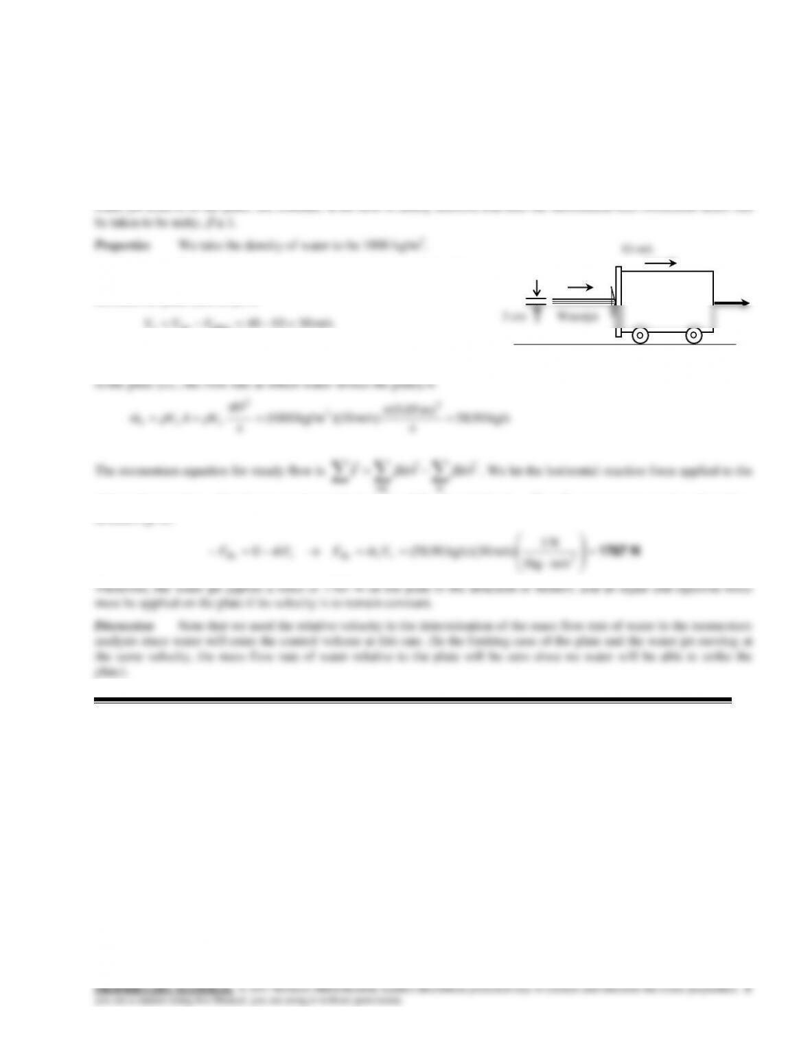
Solution A horizontal jet of water with a given velocity strikes a flat plate that is moving in the same direction at a
specified velocity. The force that the water stream exerts against the plate is to be determined.
Assumptions 1 The flow is steady and incompressible. 2 The water splatters in all directions in the plane of the plate. 3
The water jet is exposed to the atmosphere, and thus the pressure of the water jet and the splattered water is the atmospheric
pressure, which is disregarded since it acts on all surfaces. 4 The vertical forces and momentum fluxes are not considered
since they have no effect on the horizontal force exerted on the plate. 5 The velocity of the plate, and the velocity of the
Analysis We take the plate as the control volume, and the flow
direction as the positive direction of x axis. The relative velocity
between the plate and the jet is
Therefore, we can view the plate as being stationary and the jet to be
moving with a velocity of 30 m/s. The mass flow rate of water relative
inout
plate in the negative x direction to counteract the impulse of the water jet be FRx. Then the momentum equation along the x
direction gives
N 1767
2
m/s1kg
N 1
m/s) kg/s)(30 90.58( 0 rrRxiRx VmFVmF
Therefore, the water jet applies a force of 1767 N on the plate in the direction of motion, and an equal and opposite force
must be applied on the plate if its velocity is to remain constant.
Discussion Note that we used the relative velocity in the determination of the mass flow rate of water in the momentum
analysis since water will enter the control volume at this rate. (In the limiting case of the plate and the water jet moving at
the same velocity, the mass flow rate of water relative to the plate will be zero since no water will be able to strike the
plate).
40 m/s
Waterjet
10 m/s
5 cm
FRx
13-36
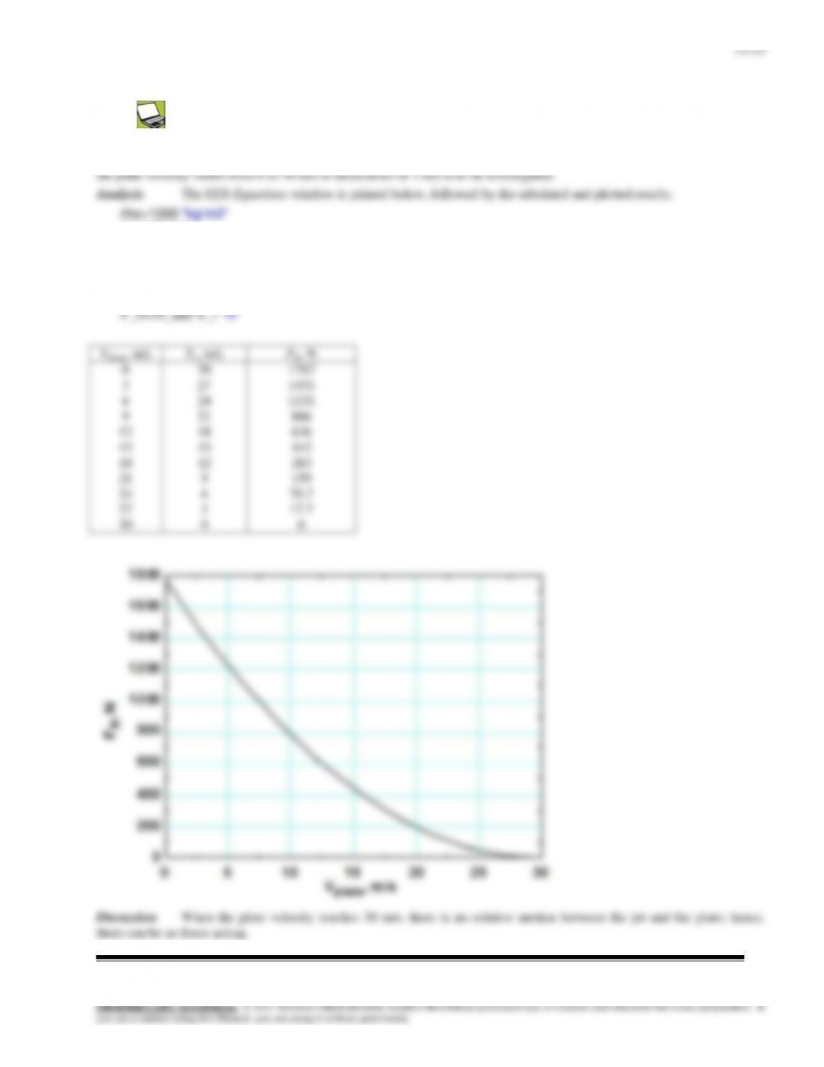
Solution The previous problem is reconsidered. The effect of the plate velocity on the force exerted on the plate as
D=0.05 “m“
V_jet=30 “m/s”
Ac=pi*D^2/4
V_r=V_jet-V_plate
m_dot=rho*Ac*V_r
13–26
13-37E
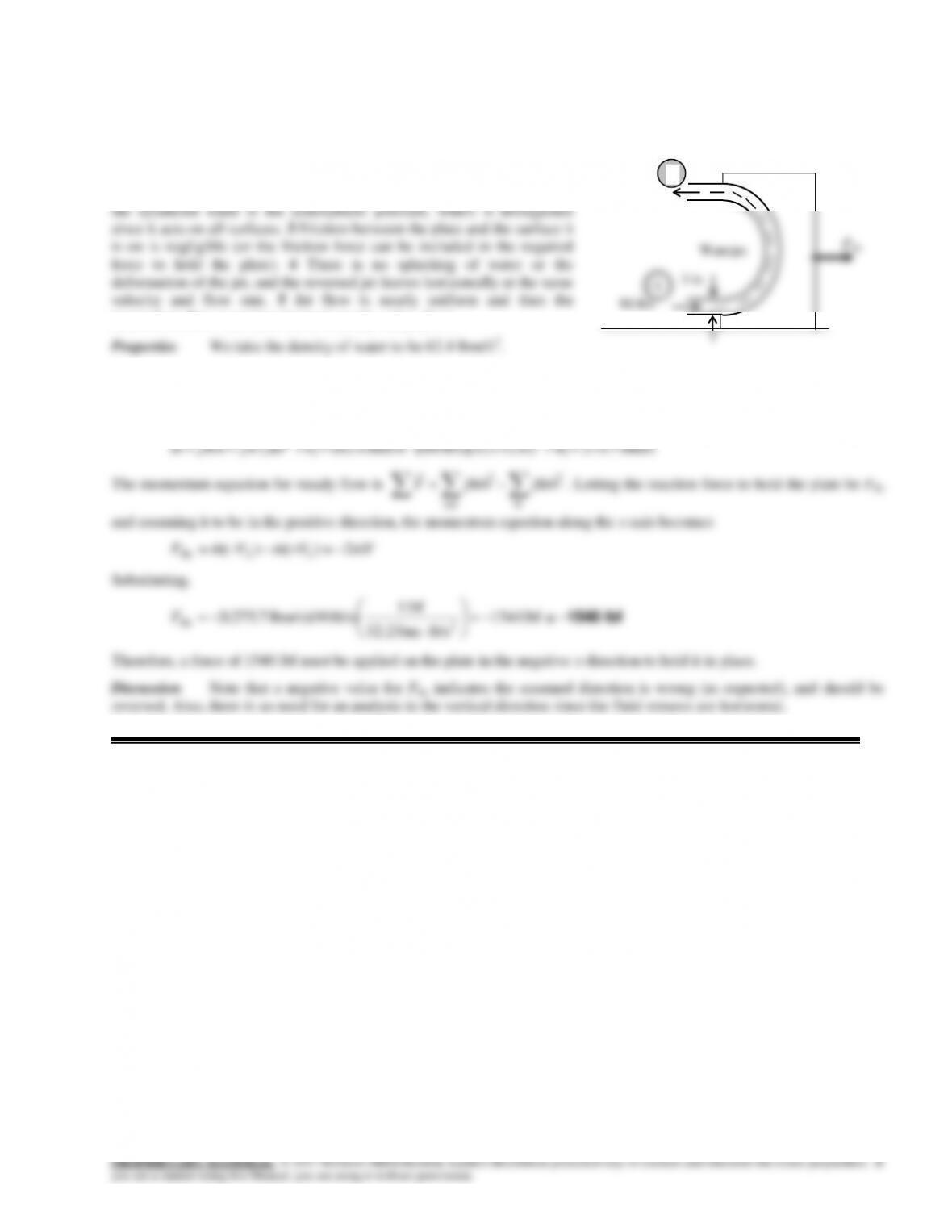
Solution A horizontal water jet strikes a curved plate, which deflects the water back to its original direction. The
force required to hold the plate against the water stream is to be determined.
Assumptions 1 The flow is steady and incompressible. 2 The water jet
is exposed to the atmosphere, and thus the pressure of the water jet and
1
momentum-flux correction factor is nearly unity,
1.
Analysis We take the plate together with the curved water jet as the control volume, and designate the jet inlet by 1
and the outlet by 2. We also designate the horizontal coordinate by x (with the direction of incoming flow as being the
positive direction). The continuity equation for this one–inlet one-outlet steady flow system is
mmm 21
where
lbm/s 7.275]4/ft) 12/3([ft/s) 90)(lbm/ft (62.4]4/[ 232
DVVAm
The momentum equation for steady flow is
inout
VmVmF
. Letting the reaction force to hold the plate be FRx
and assuming it to be in the positive direction, the momentum equation along the x axis becomes
VmVmVmFRx 2)()( 12
Substituting,
lbf 1540
lbf 1541
ft/slbm 32.2
lbf 1
ft/s) lbm/s)(90 7.275(2 2
Rx
F
Therefore, a force of 1540 lbf must be applied on the plate in the negative x direction to hold it in place.
Discussion Note that a negative value for FRx indicates the assumed direction is wrong (as expected), and should be
reversed. Also, there is no need for an analysis in the vertical direction since the fluid streams are horizontal.
90 ft/s
2
13-38
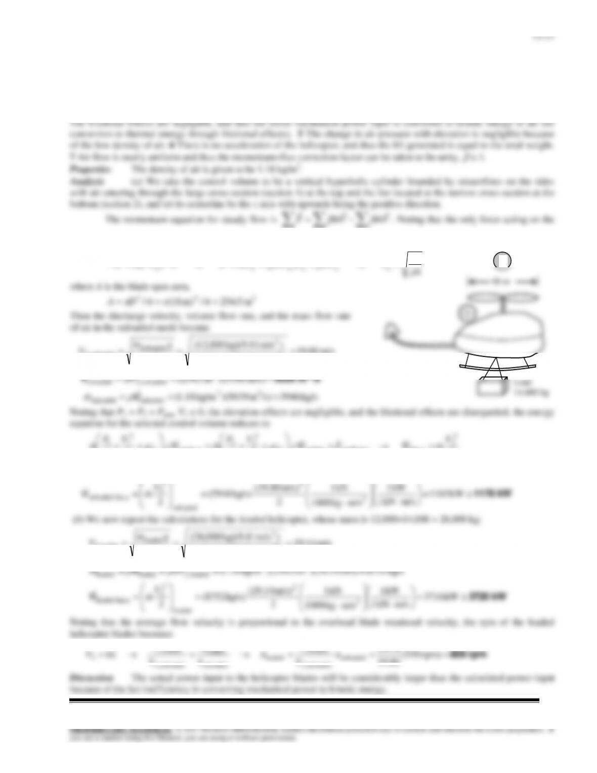
Solution A helicopter hovers at sea level while being loaded. The volumetric air flow rate and the required power
input during unloaded hover, and the rpm and the required power input during loaded hover are to be determined.
Assumptions 1 The flow of air is steady and incompressible. 2 Air leaves the blades at a uniform velocity at atmospheric
pressure. 3 Air approaches the blades from the top through a large area at atmospheric pressure with negligible velocity. 4

13–28
13-39
Solution A helicopter hovers on top of a high mountain where the air density considerably lower than that at sea
level. The blade rotational velocity to hover at the higher altitude and the percent increase in the required power input to
hover at high altitude relative to that at sea level are to be determined.
Assumptions 1 The flow of air is steady and incompressible. 2 The air leaves the blades at a uniform velocity at
13–29
13–40
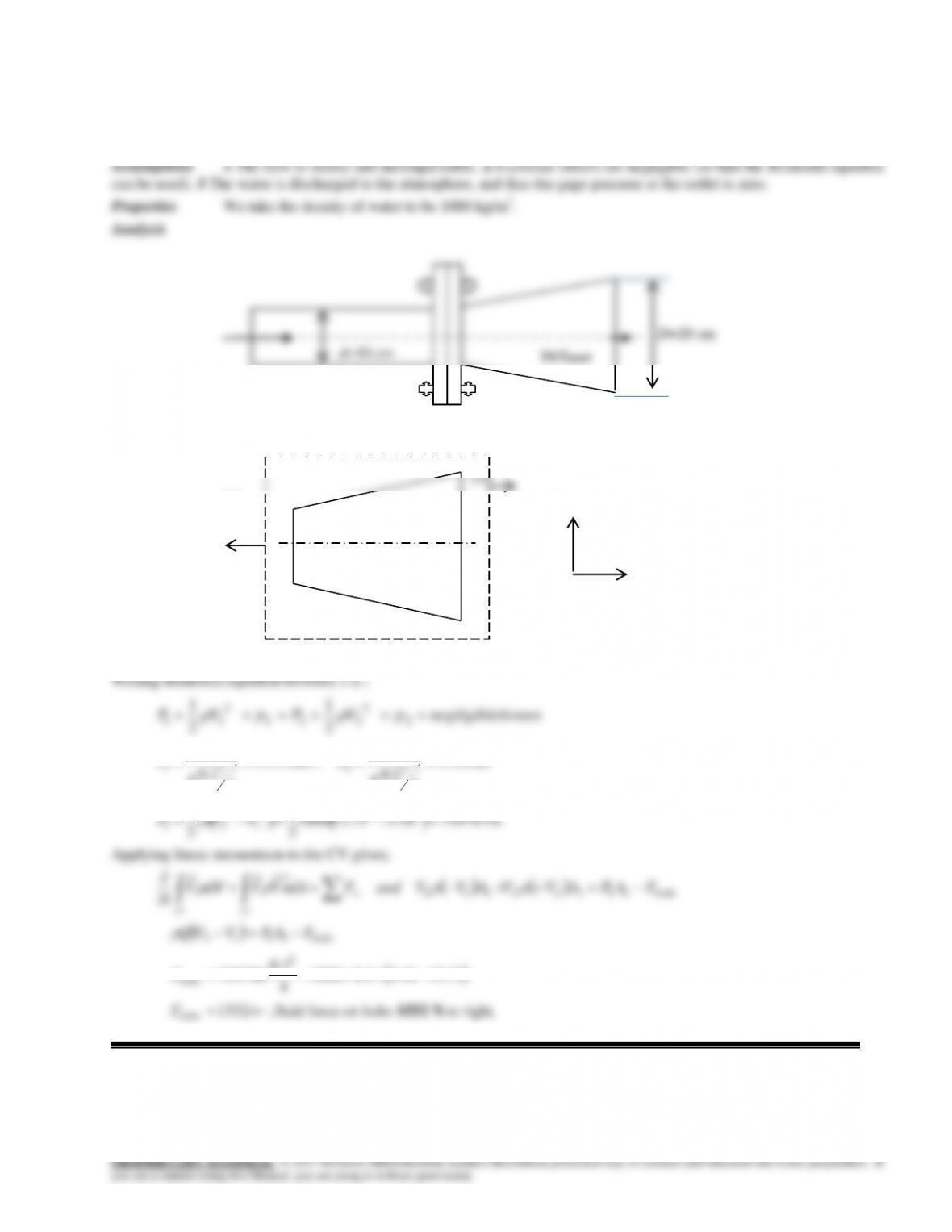
Solution Water flowing in a pipe is slowed down by a diffuser. The force exerted on the bolts due to water flow is
to be determined.
(1) y
Fbolts P2=0
x
2
73.12
4
1.0
1.0
2
1
V
m/s ,
18.3
4
2.0
1.0
2
2
V
m/s
PaVVP 7597018.373.121000
2
1
2
122
2
1
2
21
Applying linear momentum to the CV gives;
boltsx
cscv
FAPAVVAVVandFdAnVVdV
t
11222111
V
bolts
FAPVVQ 1112
73.1218.31.01000
4
1.0
75970
2
bolts
F
d=10 cm
Diffuser
13–41
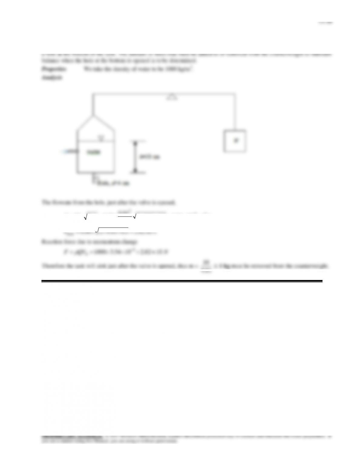
Solution The weight of a water tank is balanced by a counterweight. Water enters the tank horizontally and there is
smghCAQh/1054.35.081.92
4
04.0
90.02 33
2
81.9

13–31
13–42
Solution A wind turbine with a given span diameter and efficiency is subjected to steady winds. The power generated
and the horizontal force on the supporting mast of the turbine are to be determined.
Assumptions 1 The wind flow is steady and incompressible. 2 The efficiency of the turbine-generator is independent of
13–43
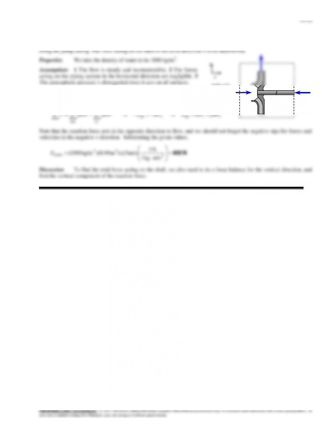
Solution Water enters a centrifugal pump axially at a specified rate and velocity, and leaves in the normal direction
Analysis We take the pump as the control volume, and the inlet
direction of flow as the positive direction of x axis. The momentum
equation for steady flow in the x (flow) direction reduces in this case to
0.09 m3/s
5 m/s
FRx
mV
13–33
13-44
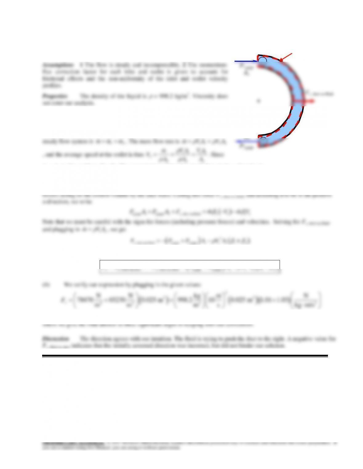
Solution A curved duct deflects a fluid. The horizontal force exerted on
the duct by the fluid is to be determined.
Analysis (a) We take the fluid within the duct as the control volume
(see sketch), and designate the inlet by 1 and the outlet by 2. We also
designate the horizontal coordinate by x (with the direction of flow as being
the positive direction). Conservation of mass for this one-inlet one-outlet
2 2 2
A1 = A2 in this problem, V2= V1. The momentum equation for steady flow in the x-direction is
on CV
out in
x
F mu mu
, where u is the horizontal velocity component: u1 = V1 and u2 = –V1. The total force on the
control volume consists of pressure forces at the inlet and outlet plus the total of all forces (including pressure and viscous
Finally, the force exerted by the fluid on the duct is the negative of this, i.e.,
2
, fluid on duct , duct on fluid 1,gage 2,gage 1 1 1 1 2x x x
F F F P P A V A
V1
1
V2
2
1
CV
13-45
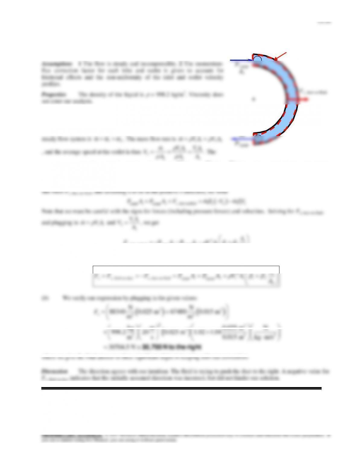
Solution A curved duct deflects a fluid. The horizontal force exerted on
the duct by the fluid is to be determined.
Analysis (a) We take the fluid within the duct as the control volume
(see sketch), and designate the inlet by 1 and the outlet by 2. We also
designate the horizontal coordinate by x (with the direction of flow as being
the positive direction). Conservation of mass for this one-inlet one-outlet
2 2 2
momentum equation for steady flow in the x-direction is
on CV
out in
x
F mu mu
, where u is the horizontal velocity
component: u1 = V1 and u2 = –V2. The total force on the control volume consists of pressure forces at the inlet and outlet
plus the total of all forces (including pressure and viscous forces) acting on the control volume by the duct walls. Calling
V1
1
V2
2
1
CV
A2
13–35
13-46
Solution A 90 reducer elbow deflects water downwards into a smaller diameter pipe. The resultant force exerted on
the reducer by water is to be determined.
Assumptions 1 The flow is steady and incompressible. 2 Frictional effects are negligible in the calculation of the pressure
drop (so that the Bernoulli equation can be used). 3 The weight of the elbow and the water in it is disregarded since the
Analysis We take the water within the elbow as the control volume (see
sketch), and designate the inlet by 1 and the outlet by 2. We also designate the
horizontal coordinate by x (with the direction of flow as being the positive
2
1
Water
8 m/s
25 cm
13–47
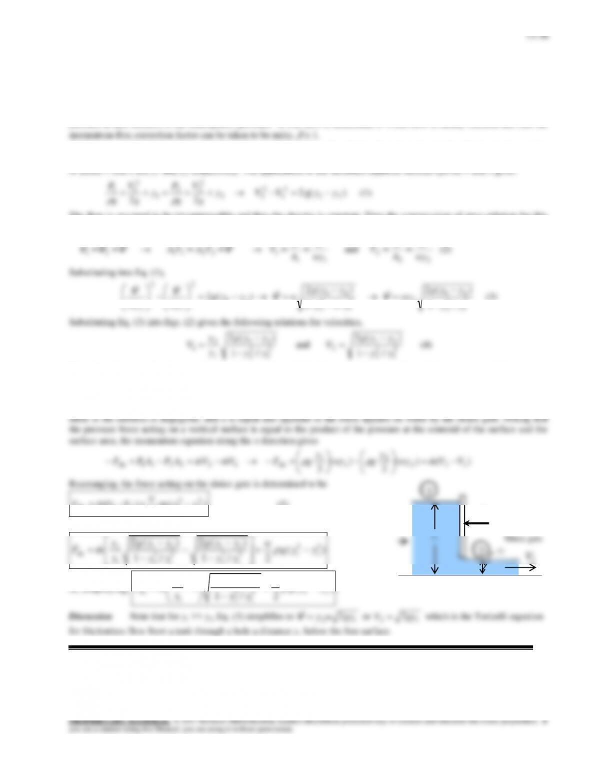
Solution The flow rate in a channel is controlled by a sluice gate by raising or lowering a vertical plate. A relation for
the force acting on a sluice gate of width w for steady and uniform flow is to be developed.
Assumptions 1 The flow is steady, incompressible, frictionless, and uniform (and thus the Bernoulli equation is
applicable.) 2 Wall shear forces at channel walls are negligible. 3 The channel is exposed to the atmosphere, and thus the
pressure at free surfaces is the atmospheric pressure. 4 The flow is horizontal. 5 Water flow is nearly uniform and thus the
Analysis We take point 1 at the free surface of the upstream flow before the gate and point 2 at the free surface of the
downstream flow after the gate. We also take the bottom surface of the channel as the reference level so that the elevations
of points 1 and 2 are y1 and y2, respectively. The application of the Bernoulli equation between points 1 and 2 gives
)g( 2
22 21
2
1
2
22
2
22
1
2
11 yyVVy
g
V
g
P
y
g
V
g
P
(1)
The flow is assumed to be incompressible and thus the density is constant. Then the conservation of mass relation for this
single stream steady flow device can be expressed as
VVVV
13–37
Review Problems
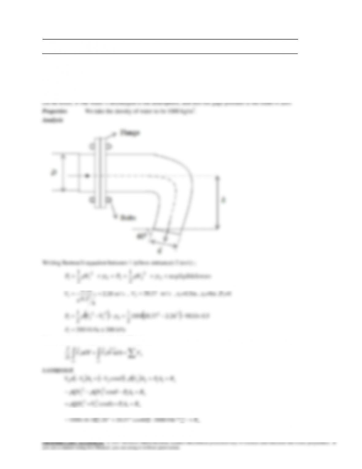
13–48
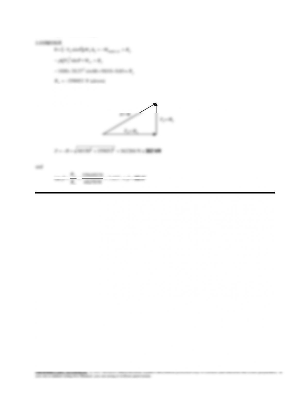
Solution Water is deflected by an elbow. The force acting on the flanges of the elbow and the angle its line of
action makes with the horizontal are to be determined.
Assumptions 1 The flow is steady and incompressible. 2 Frictional effects are negligible (so that the Bernoulli equation
2
smV /26.2
4
3.0
16.0
2
1
,
smV /37.20
2
, z1=0.5m , z2=0m ,P2=0
1
122
2
2
Linear momentum equation for the CV gives;
13–38
)(48150 leftNRx
These forces are exerted by elbow on water confined by CV. The force exerted by water on elbow is therefore;