12–55
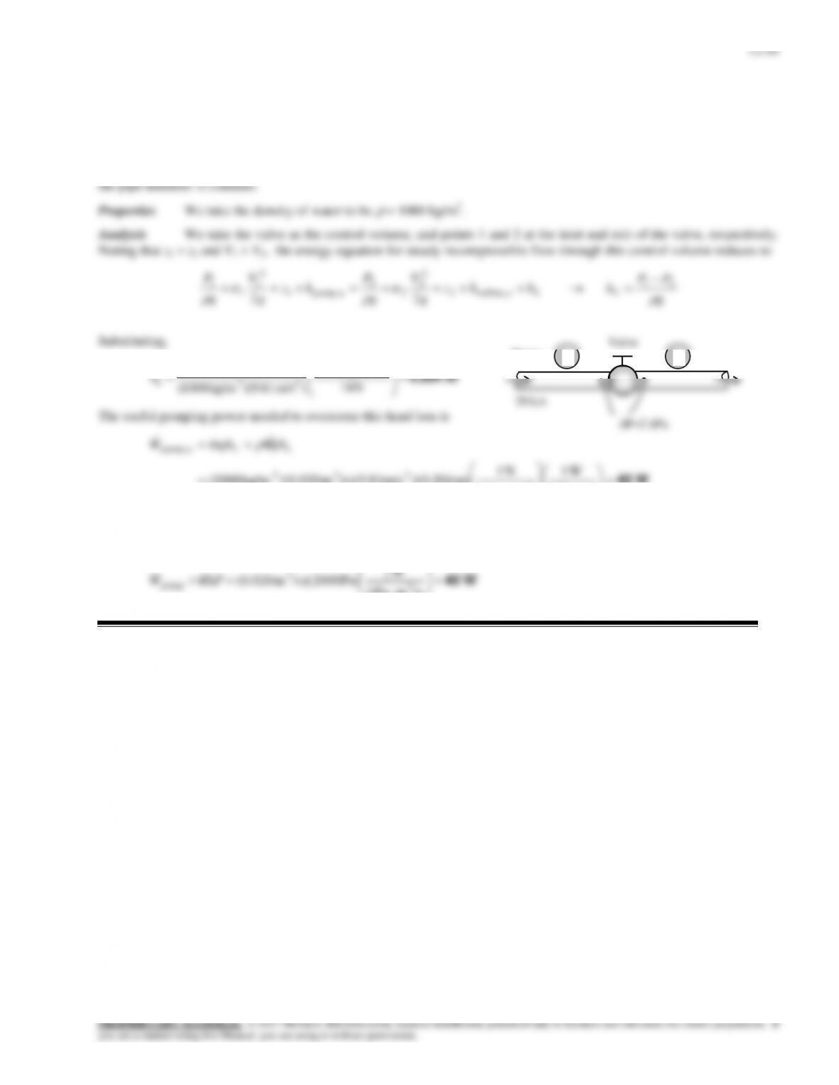
Solution Water flows through a horizontal pipe at a specified rate. The pressure drop across a valve in the pipe is
measured. The corresponding head loss and the power needed to overcome it are to be determined.
Assumptions 1 The flow is steady and incompressible. 2 The pipe is given to be horizontal (otherwise the elevation
difference across the valve is negligible). 3 The mean flow velocities at the inlet and the exit of the valve are equal since
12–42
12–56E
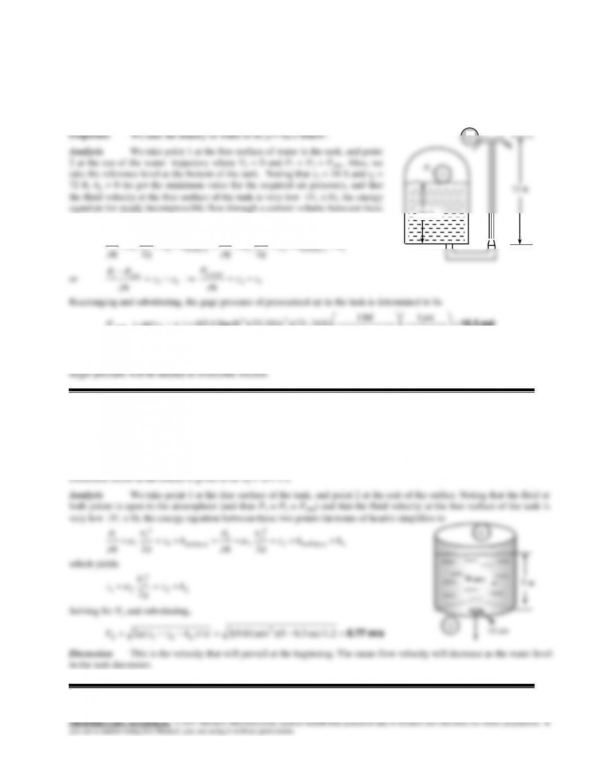
Solution A hose connected to the bottom of a pressurized tank is equipped with a nozzle at the end pointing straight
up. The minimum tank air pressure (gage) corresponding to a given height of water jet is to be determined.
Assumptions 1 The flow is steady and incompressible. 2 Friction between water and air as well as friction in the hose is
negligible. 3 The water surface is open to the atmosphere.
two points reduces to
L
hhz
g
V
g
P
hz
g
V
g
P e turbine,2
2
2
2
2
upump,1
2
1
1
1
22
or
12
1zz
g
PP atm
12
,1 zz
g
Pgage
Rearranging and substituting, the gage pressure of pressurized air in the tank is determined to be
psi 16.5
22
23
12gage1, lbf/ft 144
psi 1
ft/slbm 32.2
lbf 1
ft) 34–)(72ft/s )(32.2lbm/ft 4.62()( zzgP
Therefore, the gage air pressure on top of the water tank must be at least 10.4 psi.
Discussion The result obtained above represents the minimum value, and should be interpreted accordingly. In reality, a
12–57
Solution A water tank open to the atmosphere is initially filled with water. A sharp-edged orifice at the bottom drains
to the atmosphere. The initial discharge velocity from the tank is to be determined.
Assumptions 1 The flow is steady and incompressible. 2 The tank is open to the atmosphere. 3 The kinetic energy
L
g
V
g
P
g
V
g
P e turbine,2
34 ft
12–58
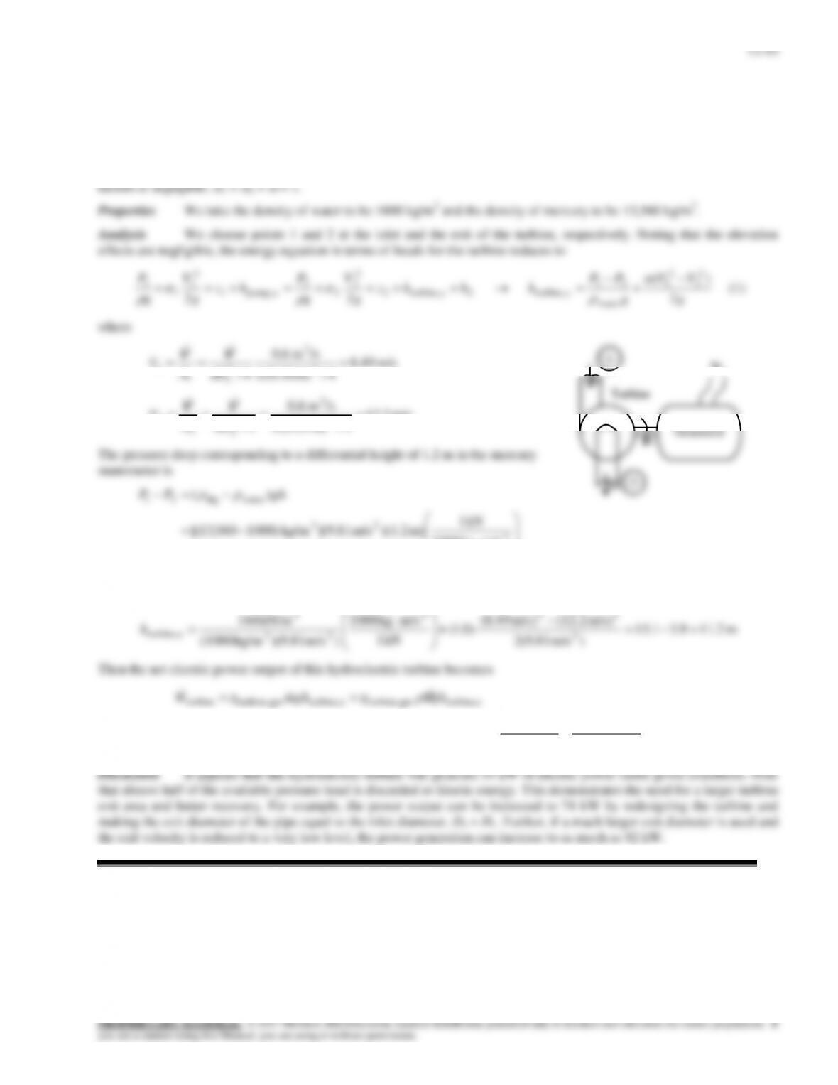
Solution Water enters a hydraulic turbine-generator system with a known flow rate, pressure drop, and efficiency.
The net electric power output is to be determined.
Assumptions 1 The flow is steady and incompressible. 2 All losses in the turbine are accounted for by turbine efficiency
and thus hL = 0. 3 The elevation difference across the turbine is negligible. 4 The effect of the kinetic energy correction
12–44
12–59
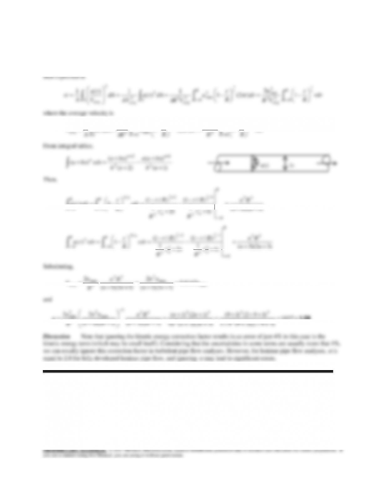
Solution The velocity profile for turbulent flow in a circular pipe is given. The kinetic energy correction factor for
this flow is to be determined.
Analysis The velocity profile is given by
n
Rruru /1
max )/1()(
with n = 9 The kinetic energy correction factor is
12–45
12–60
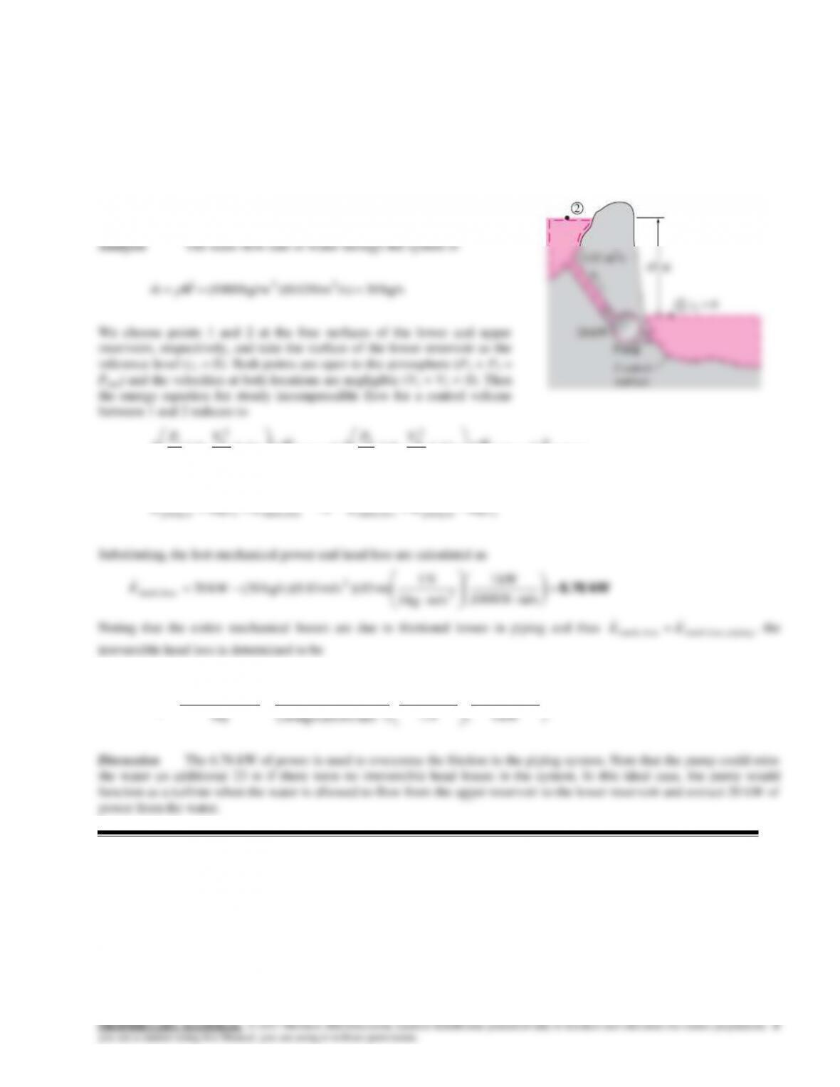
Solution Water is pumped from a lower reservoir to a higher one. The head loss and power loss associated with this
process are to be determined.
Assumptions 1 The flow is steady and incompressible. 2 The elevation difference between the reservoirs is constant.
Properties We take the density of water to be 1000 kg/m3.
lossmech,e turbine,2
2
2
2
2
up ump,1
2
1
1
1
22 EWgz
VP
mWgz
VP
m
12–61
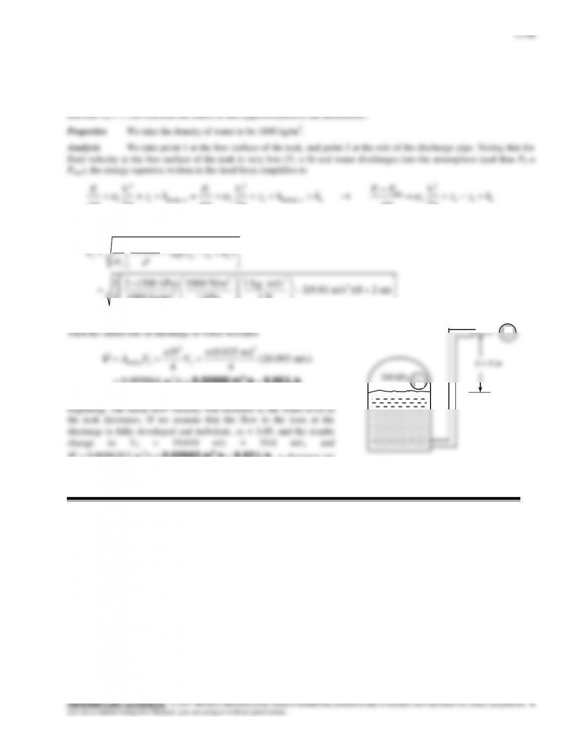
Solution Water from a pressurized tank is supplied to a roof top. The discharge rate of water from the tank is to be
determined.
Assumptions 1 The flow is steady and incompressible. 2 The effect of the kinetic energy correction factor is negligible
12–62
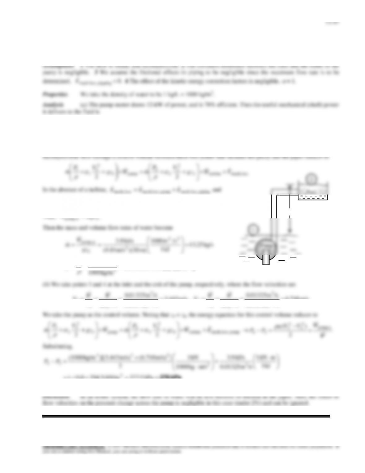
Solution Underground water is pumped to a pool at a given elevation. The maximum flow rate and the pressures at
the inlet and outlet of the pump are to be determined.
kW 9.3kW) 5)(78.0(
electricmotor–pumpu pump, WW
We take point 1 at the free surface of underground water, which is also taken as the reference level (z1 = 0), and point 2 at
the free surface of the pool. Also, both 1 and 2 are open to the atmosphere (P1 = P2 = Patm), the velocities are negligible at
both points (V1 V2 0), and frictional losses in piping are disregarded. Then the energy equation for steady
pumploss, mechpump upump, EWW
.
Thus,
2 upump, gzmW
.
kJ 1
m) )(30m/s (9.81
2
2
/sm 0.0133/ 3
sm 01325.0
kg/m 1000
kg/s 25.13 3
3
m
V
m/s 443.3
4/m) (0.07
/sm 01325.0
4/ 2
3
2
3
3
3
D
A
V
VV
,
m/s 748.6
4/m) (0.05
/sm 01325.0
4/ 2
3
2
4
4
4
D
A
V
VV
kPa 278
kPa 5.277kN/m )3.2948.16(
kJ 1
mkN 1
/sm 0.01325
kJ/s 9.3
m/skg 1000
kN 1
2
]m/s) (6.748)m/s 443.3()[kg/m (1000
2
32
223
34 PP
30 m
Pool
12–48
12–63
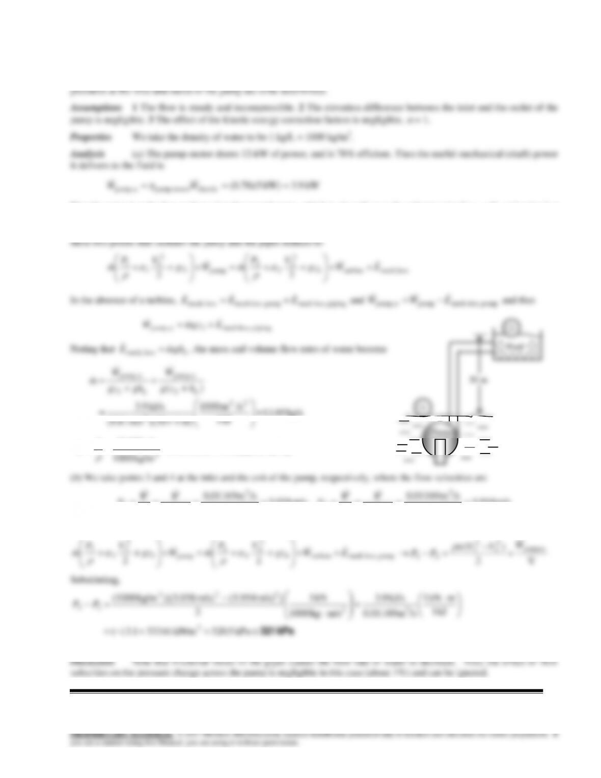
Solution Underground water is pumped to a pool at a given elevation. For a given head loss, the flow rate and the
We take point 1 at the free surface of underground water, which is also taken as the reference level (z1 = 0), and point 2 at
the free surface of the pool. Also, both 1 and 2 are open to the atmosphere (P1 = P2 = Patm), and the velocities are negligible
at both points (V1 V2 0). Then the energy equation for steady incompressible flow through a control volume between
kg/s 69.11
kJ 1
/sm 1000
m) 4 )(30m/s (9.81
kJ/s 9.3
22
2
/sm 0.0117 3
s/m 01169.0
kg/m 1000
kg/s 69.11 3
3
m
V
m/s 038.3
4/m) (0.07
/sm 01169.0
4/ 2
3
2
3
3
3
D
A
V
VV
,
m/s 954.5
4/m) (0.05
/sm 01169.0
4/ 2
3
2
4
4
4
D
A
V
VV
We take the pump as the control volume. Noting that z3 = z4, the energy equation for this control volume reduces to
pumploss, mechturbine4
2
4
4
4
pump3
2
3
3
3
22 EWgz
VP
mWgz
VP
m
V
2
)( upump,
2
4
2
3
34
W
VV
PP
Substituting,
kPa 321
kPa 5.320kN/m )6.3331.13(
kJ 1
mkN 1
/sm 0.01169
kJ/s 9.3
m/skg 1000
kN 1
2
]m/s) (5.954)m/s 038.3()[kg/m (1000
2
32
223
34
PP
Pump
1
12–49
12–64E
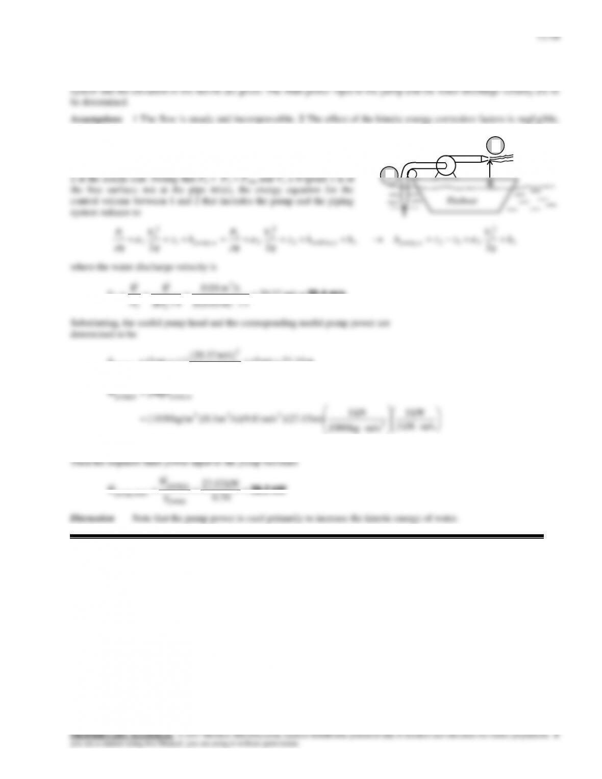
Solution Water is pumped from a lake to a nearby pool by a pump with specified power and efficiency. The head
ft 3.64
hp1
ft/slbf 550
lbf 1
ft/slbm 32.2
)ft/s /s)(32.2ft )(1.2lbm/ft (62.4
hp76.8 2
233
upump, upump,
upump,
g
W
gm
W
h
V
We choose points 1 and 2 at the free surfaces of the lake and the pool, respectively. Both points are open to the atmosphere
ft 29.3 353.64)( 12 upump, zzhhL
hp 4.0
ft/slbf 550
hp 1
ft/slbm 32.2
lbf 1
)ft (29.3)ft/s /s)(32.2ft )(1.2lbm/ft (62.4 2
233
piping loss,mech L
ghE
V
Discussion Note that the pump must raise the water an additional height of 29.3 ft to overcome the frictional losses in
pipes, which requires an additional useful pumping power of about 4 hp.
Pool
Pump
35 ft
1
2
12–65
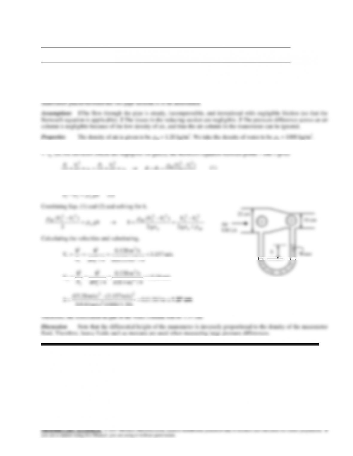
Solution A fireboat is fighting fires by drawing sea water and discharging it through a nozzle. The head loss of the
= 1.
Properties The density of sea water is given to be
=1030 kg/m3.
Analysis We take point 1 at the free surface of the sea and point
m/s 20.4 m/s 37.20
4/m) (0.05
/sm 04.0
4/ 2
3
2
2
2
2
D
A
V
VV
m 27.15m) 3(
)m/s 2(9.81
m/s) (20.37
(1)m) (3 2
2
,
upump
h
kW 27.43
m/skN 1
kW 1
m/skg 1000
kN 1
)m (27.15)m/s /s)(9.81m )(0.1kg/m (1030 2
233
,upump,
upump
ghW
V
Then the required shaft power input to the pump becomes
kW 39.2 0.70
kW 43.27
pump
upump,
shaft pump,
W
W
Discussion Note that the pump power is used primarily to increase the kinetic energy of water.
3 m
2
12–51
Review Problems
12–66
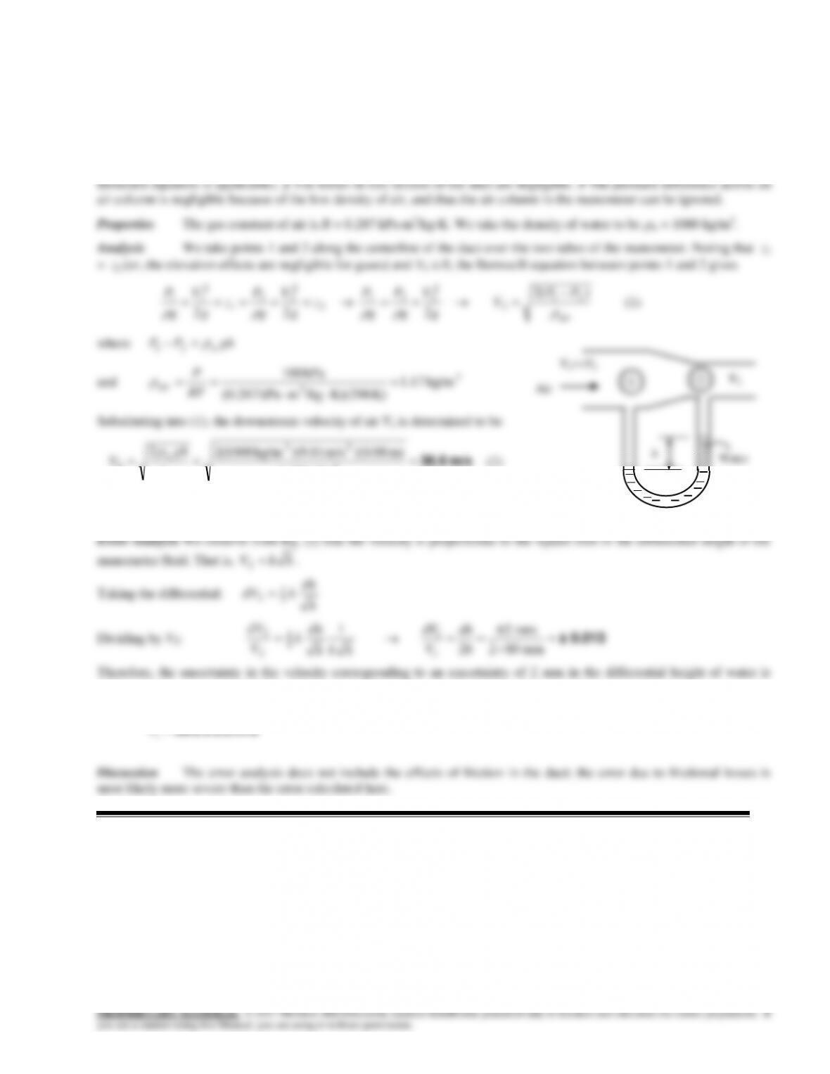
Solution Air flows through a pipe that consists of two sections at a specified rate. The differential height of a water
Analysis We take points 1 and 2 along the centerline of the pipe over the two tubes of the manometer. Noting that z1
2
22
212
1
g
g
g
g
We let the differential height of the water manometer be h. Then the pressure difference P2 – P1 can also be expressed as
12–52
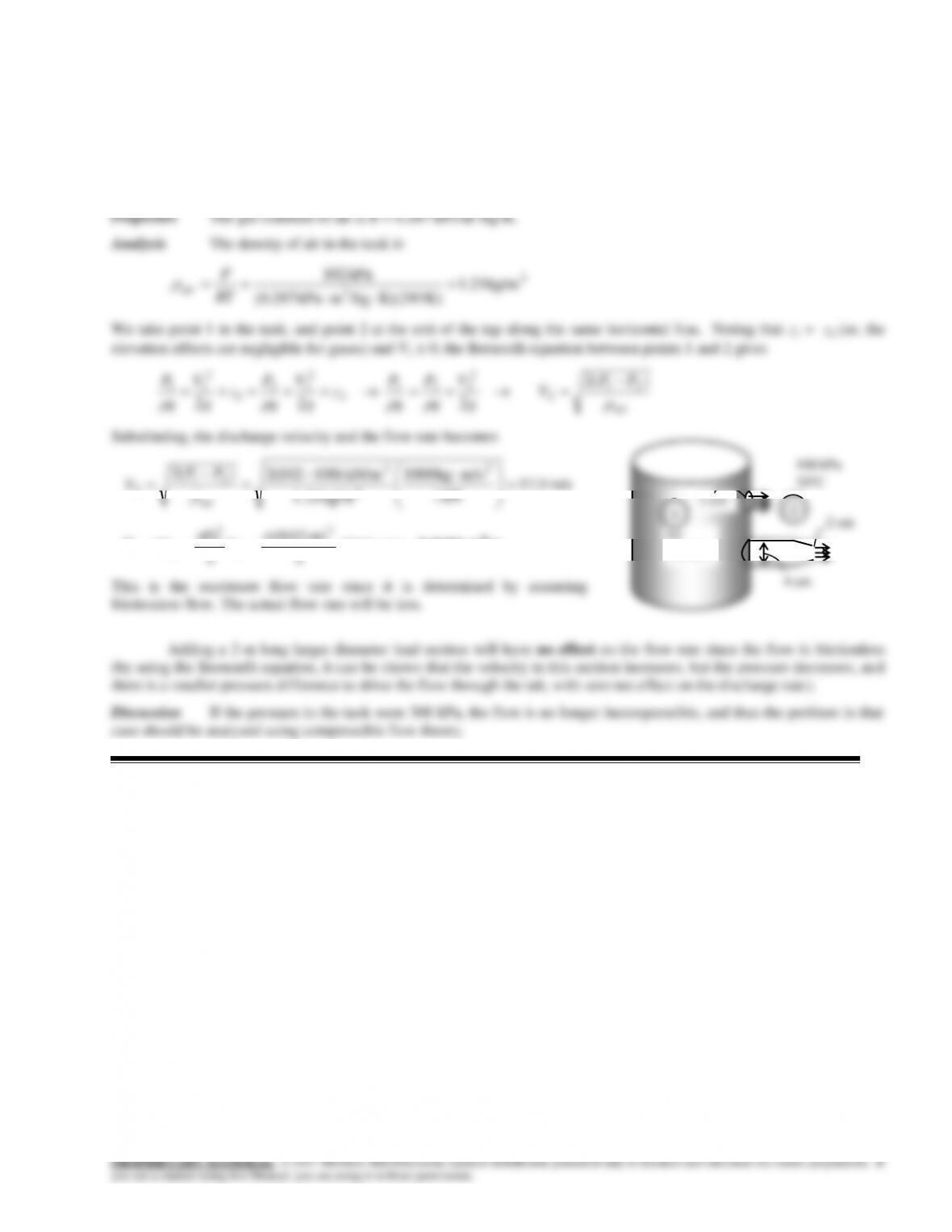
12–67
Solution Air flows through a horizontal duct of variable cross-section. For a given differential height of a water
manometer placed between the two pipe sections, the downstream velocity of air is to be determined, and an error analysis
is to be conducted.
Assumptions 1 The flow through the duct is steady, incompressible, and irrotational with negligible friction (so that the
12–53
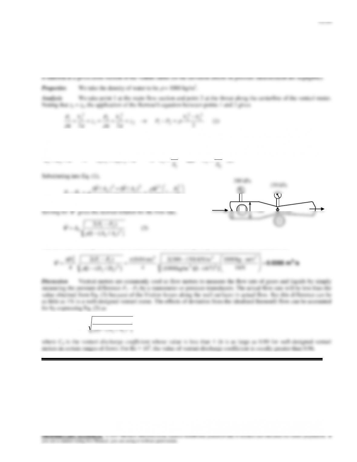
12–68
Solution A tap is opened on the wall of a very large tank that contains air. The maximum flow rate of air through the
tap is to be determined, and the effect of a larger diameter lead section is to be assessed.
Assumptions Flow through the tap is steady, incompressible, and irrotational with negligible friction (so that the flow rate
is maximum, and the Bernoulli equation is applicable).
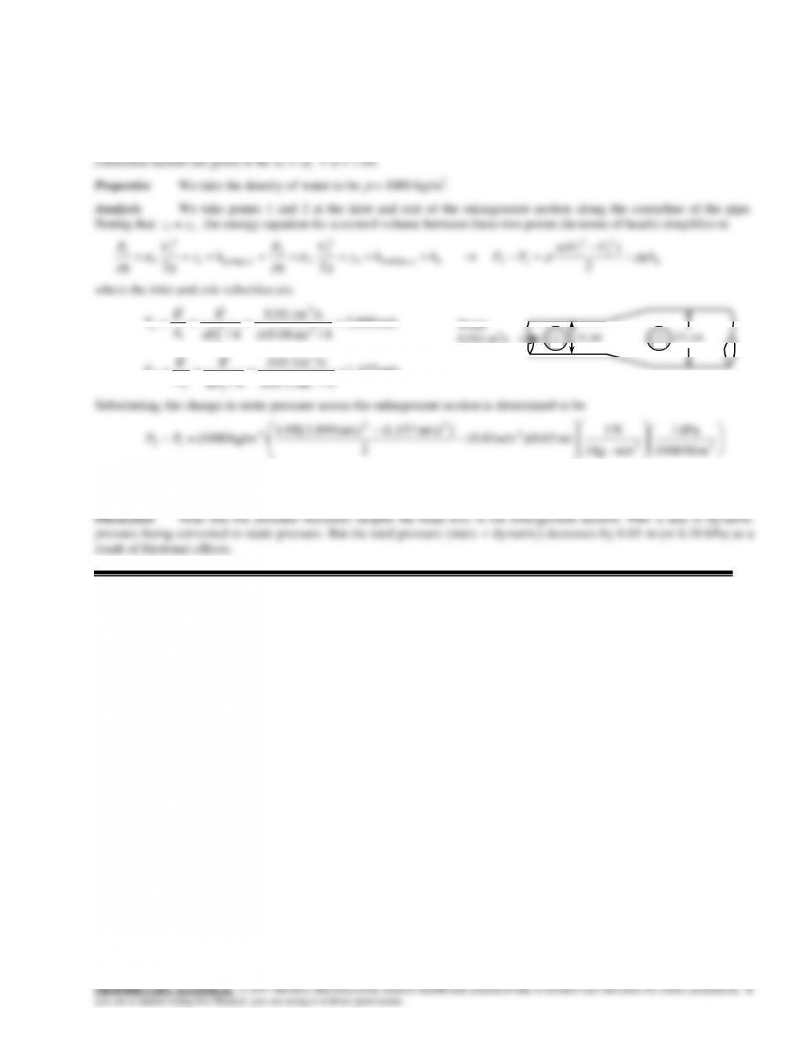
12–69
Solution Water is flowing through a venturi meter with known diameters and measured pressures. The flow rate of
water is to be determined for the case of frictionless flow.
Assumptions 1 The flow through the venturi is steady, incompressible, and irrotational with negligible friction (so that the
Bernoulli equation is applicable). 2 The flow is horizontal so that elevation along the centerline is constant. 3 The pressure
2
22
g
g
g
g
The flow is assumed to be incompressible and thus the density is constant. Then the conservation of mass relation for this
single stream steady flow device can be expressed as
VV
12–55
12–70
Solution Water flows through the enlargement section of a horizontal pipe at a specified rate. For a given head loss,
the pressure change across the enlargement section is to be determined.
Assumptions 1 The flow through the pipe is steady and incompressible. 2 The pipe is horizontal. 3 The kinetic energy
m/s 890.3
4/m) (0.06
/sm 011.0
4/ 2
3
2
1
1
1
D
A
V
VV
m/s 157.1
4/m) (0.11
/sm 011.0
4/ 2
3
2
2
2
2
D
A
V
VV
kPa 0.865
N/m 1000
kPa 1
m/skg 1
N 1
m) 65.0)(m/s (9.81
2
])m/s 157.1(m/s) 890.3[(05.1
)kg/m 1000( 22
2
22
3
12 PP
Therefore, the water pressure increases by 0.865 kPa across the enlargement section.
6 cm
11 cm
Water
0.011 m3/s
1
2
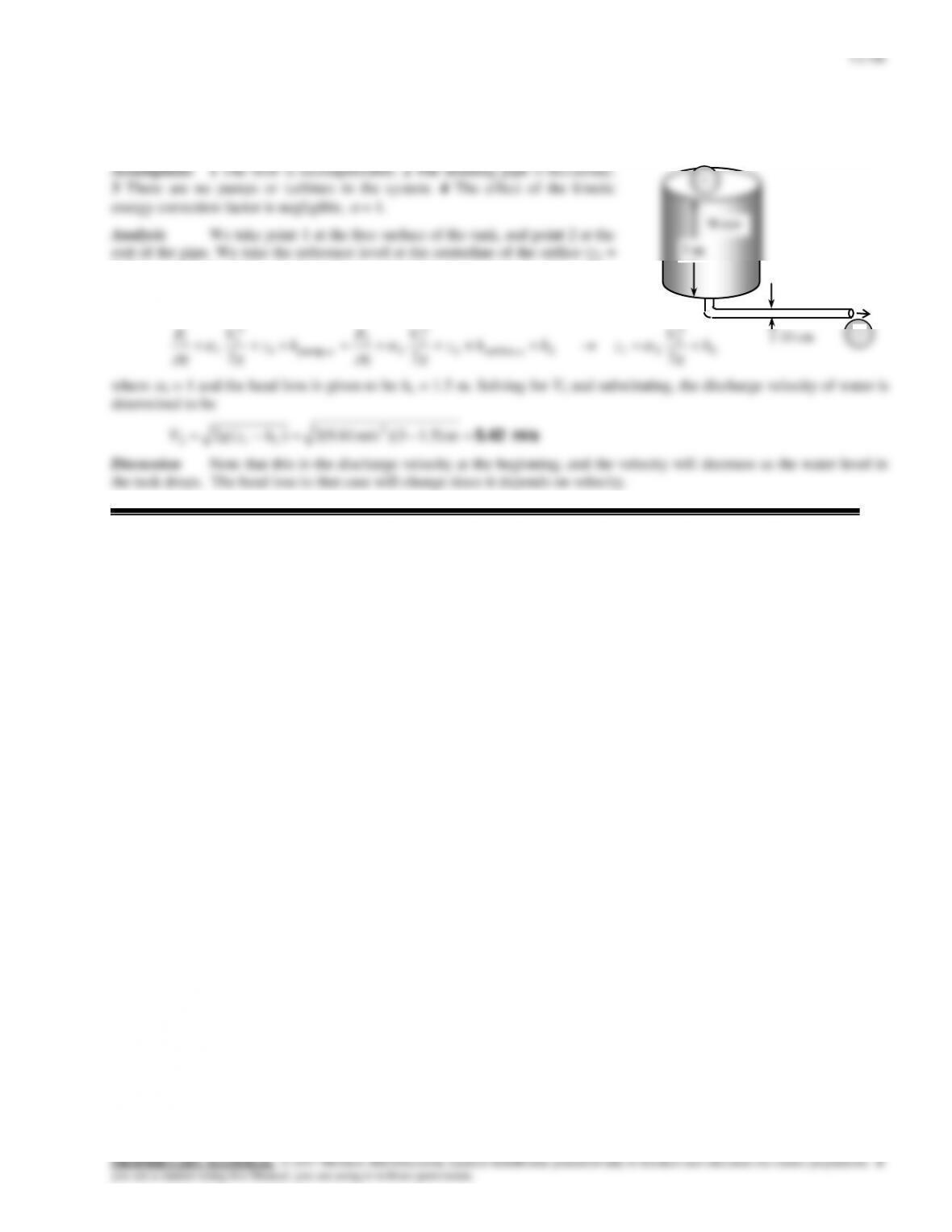
12-71
Solution A water tank open to the atmosphere is initially filled with water. A sharp-edged orifice at the bottom drains
to the atmosphere through a long pipe with a specified head loss. The initial discharge velocity is to be determined.
0. Noting that the fluid at both points is open to the atmosphere (and thus P1 =
P2 = Patm) and that the fluid velocity at the free surface is very low (V1 0), the
energy equation between these two points (in terms of heads) simplifies to
2
22
2
2
21e turbine,2
2
2
2
2
upump,1
2
1
1
1
LL h
g
V
zhhz
g
V
g
P
hz
g
V
g
P
where
2 = 1 and the head loss is given to be hL = 1.5 m. Solving for V2 and substituting, the discharge velocity of water is
determined to be
m/s 5.42 m )5.13)(m/s 81.9(2)(2 2
12 L
hzgV
Discussion Note that this is the discharge velocity at the beginning, and the velocity will decrease as the water level in
the tank drops. The head loss in that case will change since it depends on velocity.
10 cm
80 m
2
12–57
12–72
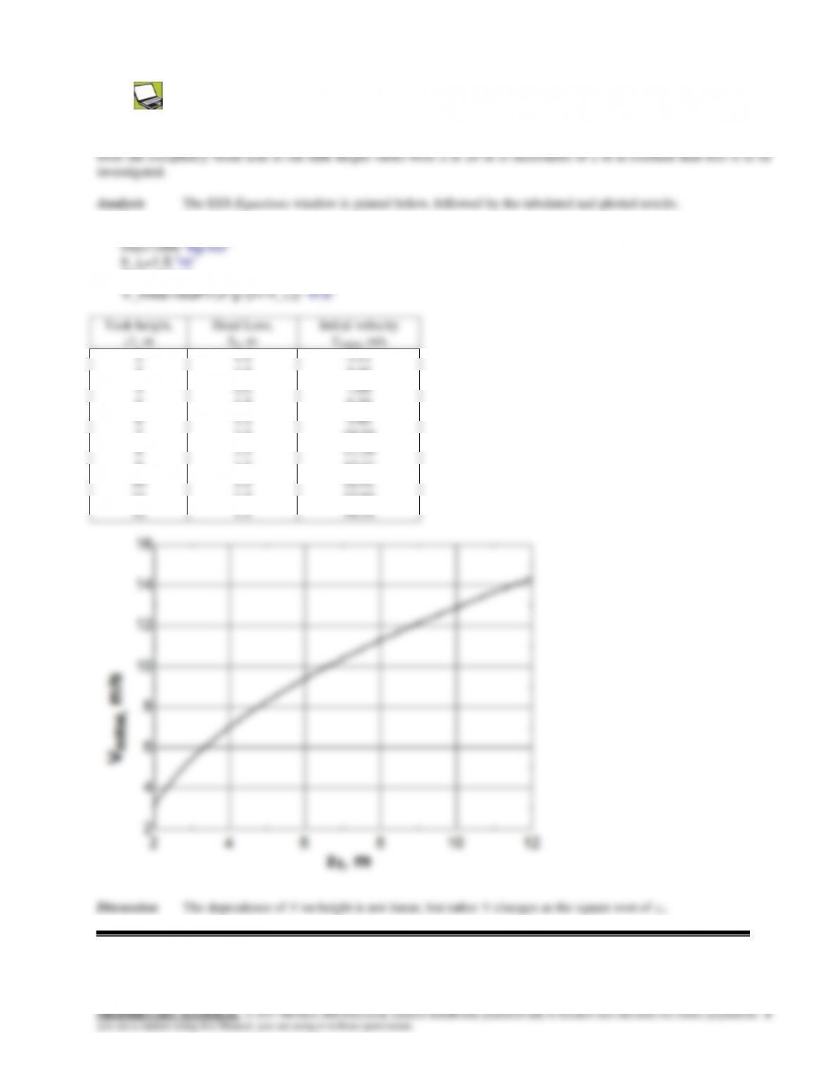
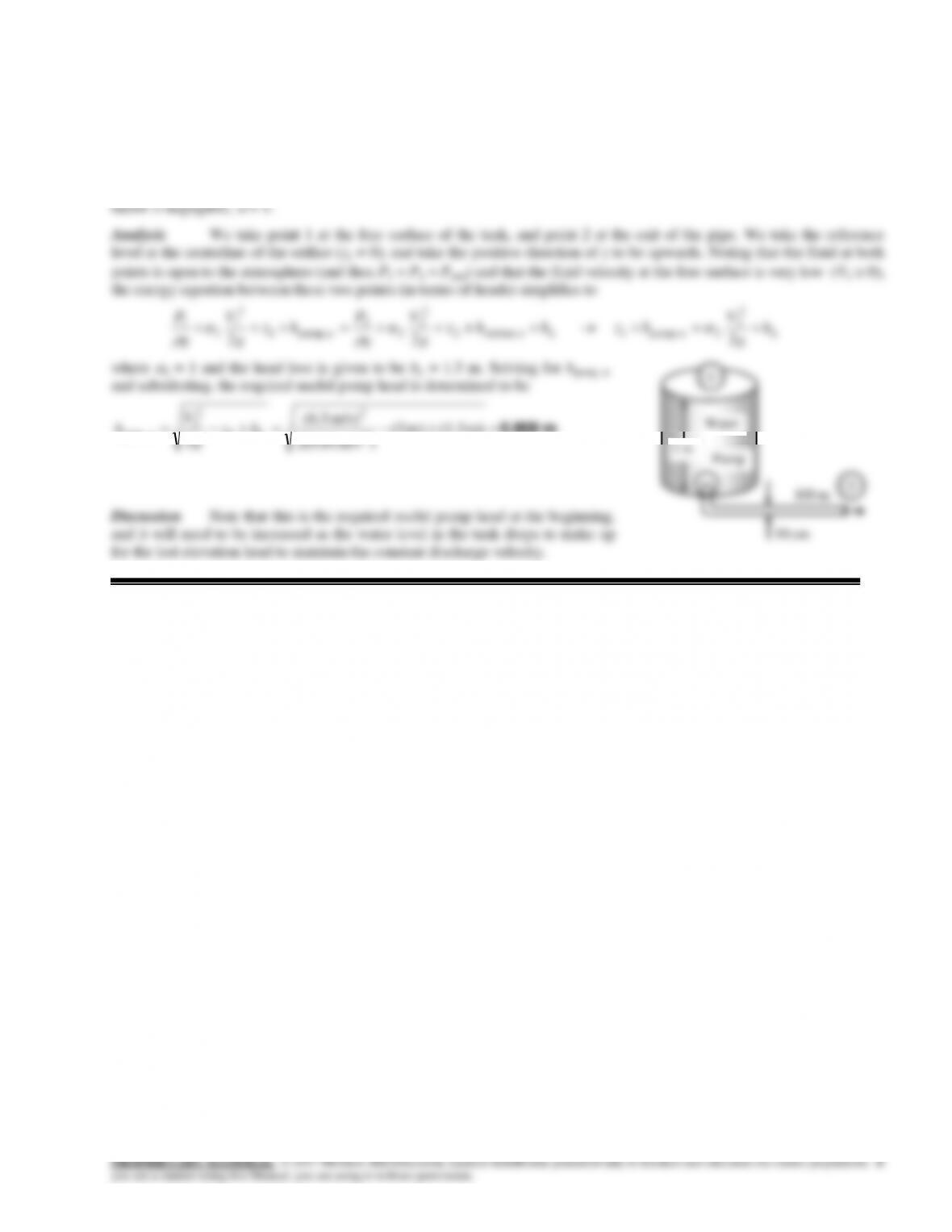
Solution The previous problem is reconsidered. The effect of the tank height on the initial discharge velocity of water
g=9.81 “m/s2″
D=0.10 “m“
12–58
12-73
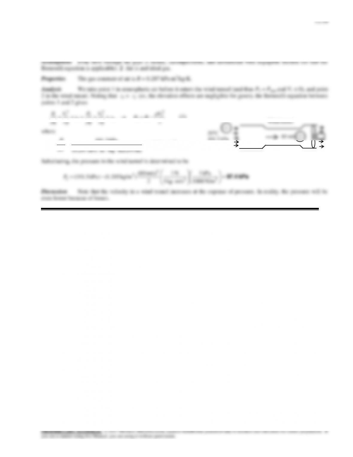
Solution A water tank open to the atmosphere is initially filled with water. A sharp-edged orifice at the bottom drains
to the atmosphere through a long pipe equipped with a pump with a specified head loss. The required pump head to assure a
certain velocity is to be determined.
Assumptions 1 The flow is incompressible. 2 The draining pipe is horizontal. 3 The effect of the kinetic energy correction
m 0.808 m) (1.5m) (3
)m/s 81.9(2
m/s) 5.6(
22
2
1
2
2
,Lupıım hz
g
V
h
3 m
Water
Pump
12–74
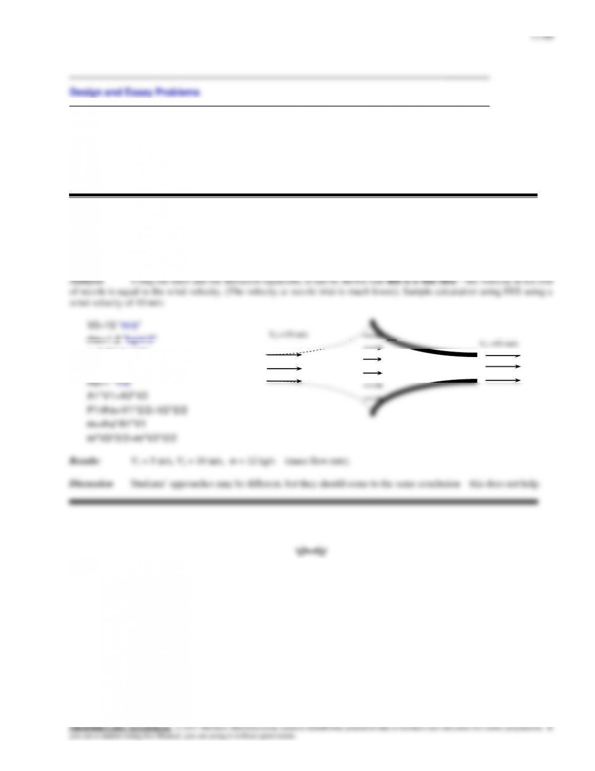
Solution A wind tunnel draws atmospheric air by a large fan. For a given air velocity, the pressure in the tunnel is to
be determined.
2
22
2
2
122
2
22
1
2
11 V
PPz
g
V
g
P
z
g
V
g
P
(1)
3
3kg/m 205.1
K) K)(293/kgmkPa (0.287
kPa 3.101
RT
P
80 m/s
Wind tunnel
20C
101.3 kPa
1
2
12-75 to 12-78
Solution Students’ essays and designs should be unique and will differ from each other.
12-78
Solution We are to evaluate a proposed modification to a wind turbine.
V0 =10 m/s
g=9.81 “m/s2″
A1=2 “m2”
V1 =5 m/s
V2 =10 m/s