12–30
Solution A hand-held bicycle pump with a liquid reservoir is used as an atomizer by forcing air at a high velocity
through a small hole. We are to explain how the liquid gets sucked up the tube.
Assumptions 1 The flows of air and water are steady and nearly incompressible. 2 Air is an ideal gas. 3 The liquid
reservoir is open to the atmosphere. 4 The device is held horizontally. 5 The water velocity through the tube is low (the
water in the tube is nearly hydrostatic).
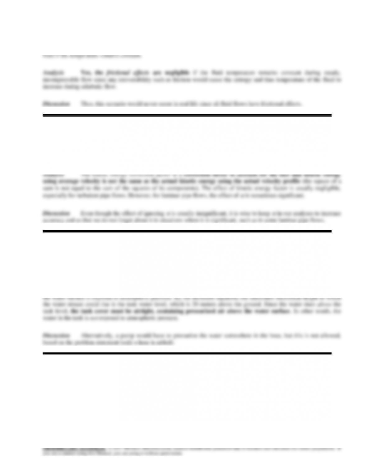
Analysis At first glance, we are tempted to use the Bernoulli
equation, thinking that the pressure in the air jet would be lower than
atmospheric due to its high speed. However, as stated in the problem
statement, the pressure through an incompressible jet exposed to the
atmosphere is nearly atmospheric pressure everywhere. Thus, in the
absence of the tube, the pressure in the air jet just above the tube
Air
Liquid
rising
12–22
12–31
Solution Water is siphoned from a reservoir. The minimum flow rate that can be achieved without cavitation
occurring in the piping system and the maximum elevation of the highest point of the piping system to avoid cavitation are
to be determined.
Assumptions 1 The flow through the pipe is steady, incompressible and irrotational with negligible frictional effects (so
g
g
22
4
1
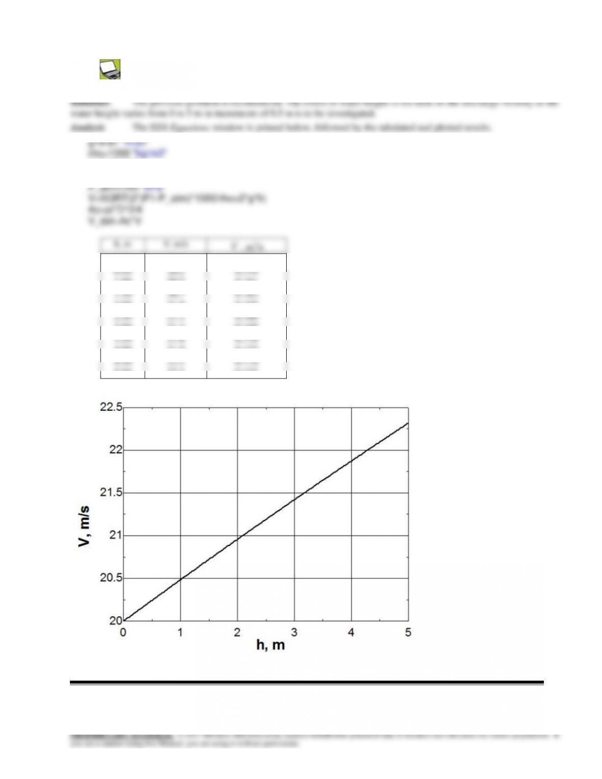
V4 = 9.904 m/s
On the other hand, from the continuity,
DDdd VAVA
,
DD
d
D
dV
d
D
V
A
A
V2
2
)(
16
g
g
22
2
1
62.19
35.23
205
9810
101325 2
2
m
P
789.29328.15 2
m
P
,
.461.14
2m
Pm
2
m
P
12–23
g
Vd
29810
10.338.2
25
9810
101325 2
max
3
09.13
2
2
max
g
Vd
/sm0.125 3
16
4
1.0 2
ddVAV
g
2
.238.0
9810
2338
min3m
P
g
V
ZD
2
238.005
9810
101325 2
max.3
12–32
Solution The gage pressure in the water mains of a city at a particular location is given. It is to be determined if this
main can serve water to neighborhoods that are at a given elevation relative to this location.
Assumptions Water is incompressible and thus its density is constant.
Properties We take the density of water to be
= 1000 kg/m3.
12–33
Solution Water discharges to the atmosphere from the orifice at the bottom of a pressurized tank. Assuming
frictionless flow, the discharge rate of water from the tank is to be determined.
orifice, which is also taken to be the reference level (z2 = 0). Noting that the fluid velocity
at the free surface is very low (V1 0) and water discharges into the atmosphere (and
m/s 7.18m) 5.2)(m/s 81.9(2
N 1
m/skg 1
kPa 1
N/m 1000
kg/m 1000
kPa )100250(2
2
)(2 2
2
2
3
1
21
2
gz
PP
V
2.5 m
Water
Tank
12–25
12–34
d=0.10 “m”
P1=300 “kPa”
12–35E
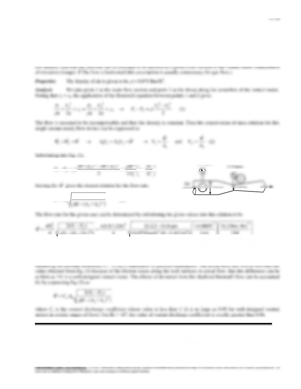
Solution Air is flowing through a venturi meter with known diameters and measured pressures. A relation for the
flow rate is to be obtained, and its numerical value is to be determined.
Assumptions 1The flow through the venturi is steady, incompressible, and irrotational with negligible frictional effects
(so that the Bernoulli equation is applicable). 2 The effect of air column on the pressure change is negligible because of its
12–27
12–36
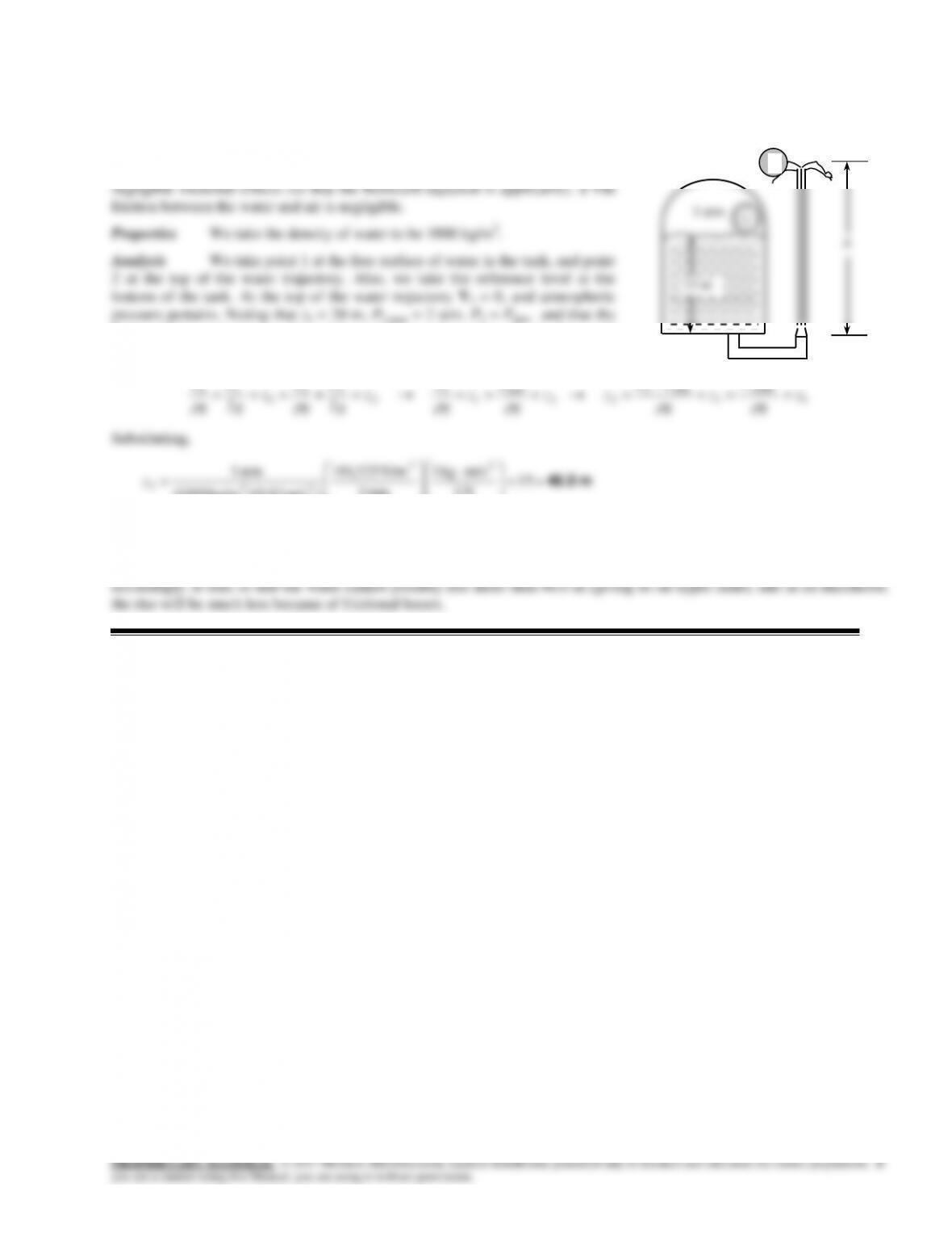
Solution The water height in an airtight pressurized tank is given. A hose pointing straight up is connected to the
bottom of the tank. The maximum height to which the water stream could rise is to be determined.
Assumptions 1 The flow is steady, incompressible, and irrotational with
1
fluid velocity at the free surface of the tank is very low (V1 0), the Bernoulli
equation between these two points simplifies to
1
gage1,
1
1
221
1
2
2
22
1
2
11
22 z
g
P
z
g
PP
zz
g
P
z
g
P
z
g
V
g
P
z
g
V
g
Patmatm
Substituting,
m 46.0
15
N 1
m/skg 1
atm 1
N/m 325,101
)m/s 81.9)(kg/m 1000(
atm 3 2
2
23
2
z
Therefore, the water jet can rise as high as 46.0 m into the sky from the ground.
Discussion The result obtained by the Bernoulli equation represents the upper limit, and should be interpreted
2
PROPRIETARY MATERIAL. © 2017 McGraw-Hill Education. Limited distribution permitted only to teachers and educators for course preparation. If
you are a student using this Manual, you are using it without permission.
12–37C
Solution We are to define and discuss useful pump head.
12–38C
Solution We are to analyze whether temperature can decrease during steady adiabatic flow of an incompressible
12–39C
Solution We are to define and discuss irreversible head loss.
12–29
12–40C
Solution We are to determine if frictional effects are negligible in the steady adiabatic flow of an incompressible
12–41C
Solution We are to define and discuss the kinetic energy correction factor.
12–42C
Solution We are to analyze the cause of some strange behavior of a water jet.
Analysis The problem does not state whether the water in the tank is open to the atmosphere or not. Let’s assume that
12–43C
Solution We are to analyze a suggestion regarding a garden hose.
12–44C
Solution We are to analyze discharge of water from a tank under different conditions.
Analysis (a) Yes, the discharge velocity from the bottom valve will be higher since velocity is proportional to the square
12–31
12–45E
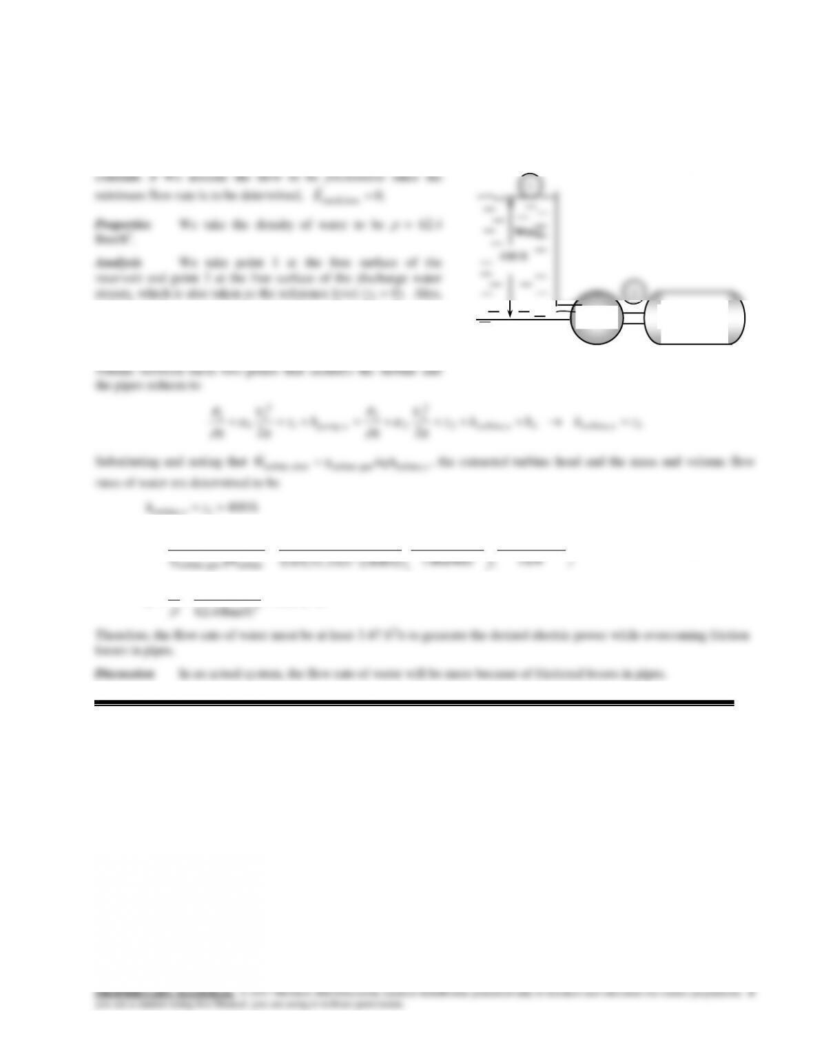
Solution In a hydroelectric power plant, the elevation difference, the power generation, and the overall turbine–
generator efficiency are given. The minimum flow rate required is to be determined.
Assumptions 1 The flow is steady and incompressible. 2 The
water levels at the reservoir and the discharge site remain
both 1 and 2 are open to the atmosphere (P1 = P2 = Patm), the
velocities are negligible at both points (V1 = V2 = 0), and
frictional losses are disregarded. Then the energy equation in
terms of heads for steady incompressible flow through a control
lbm/s 217
lbm/s 8.216
kW 1
Btu/s 9478.0
Btu/lbm 1
/sft 037,25
ft) )(400ft/s 0.85(32.2
kW 100 22
2
turbinegen–turbine
electturbine,
gh
W
m
/sft 3.47
lbm/ft 62.4
lbm/s 8.216 3
3
m
V
Turbine
Generator
12–46E
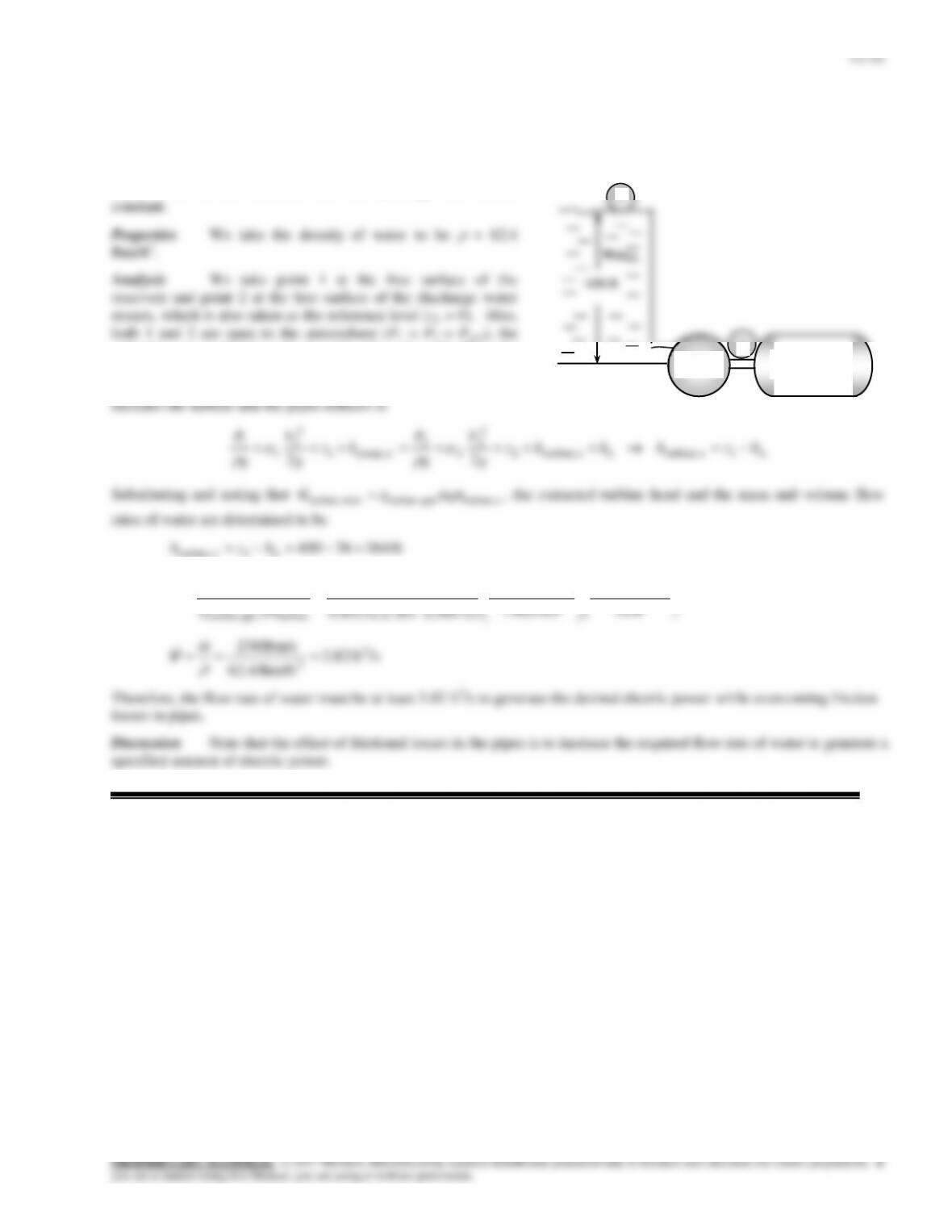
Solution In a hydroelectric power plant, the elevation difference, the head loss, the power generation, and the overall
turbine-generator efficiency are given. The flow rate required is to be determined.
Assumptions 1 The flow is steady and incompressible. 2 The
water levels at the reservoir and the discharge site remain
velocities are negligible at both points (V1 = V2 = 0). Then the
energy equation in terms of heads for steady incompressible
flow through a control volume between these two points that
lbm/s 238
kW 1
Btu/s 9478.0
Btu/lbm 1
/sft 037,25
ft) )(364ft/s 0.85(32.2
kW 100 22
2
turbinegen–turbine
electturbine,
gh
W
m
/sft 3.82
lbm/ft 62.4
lbm/s 238 3
3
m
V
Therefore, the flow rate of water must be at least 3.82 ft3/s to generate the desired electric power while overcoming friction
losses in pipes.
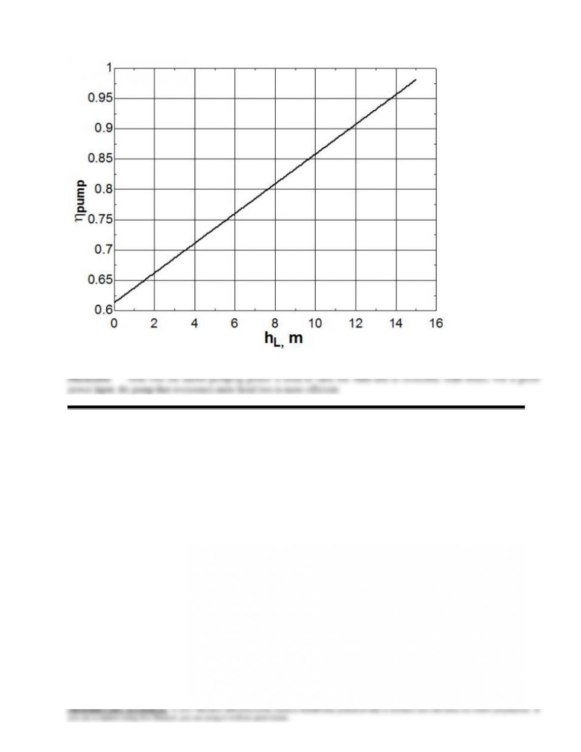
Discussion Note that the effect of frictional losses in the pipes is to increase the required flow rate of water to generate a
specified amount of electric power.
Turbine
Generator
1
2
12–33
12–47
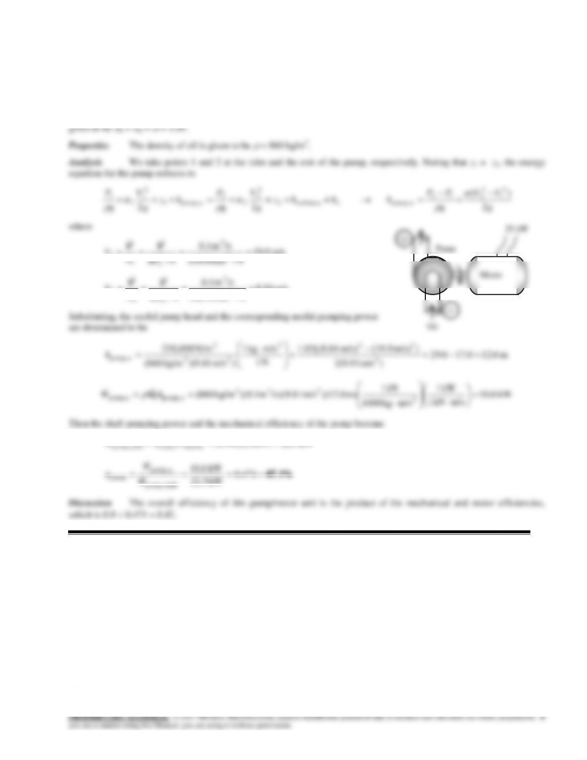
Solution A pump is pumping oil at a specified rate. The pressure rise of oil in the pump is measured, and the motor
efficiency is specified. The mechanical efficiency of the pump is to be determined.
Assumptions 1 The flow is steady and incompressible. 2 The elevation difference across the pump is negligible. 3 All the
losses in the pump are accounted for by the pump efficiency and thus hL = 0. 4 The kinetic energy correction factors are
m/s 9.19
4/m) (0.08
/sm 1.0
4/ 2
3
2
1
1
1
D
A
V
VV
m/s 84.8
4/m) (0.12
/sm 1.0
4/ 2
3
2
2
2
2
D
A
V
VV
Oil
Pump
Motor
2
1
12–34
12–48
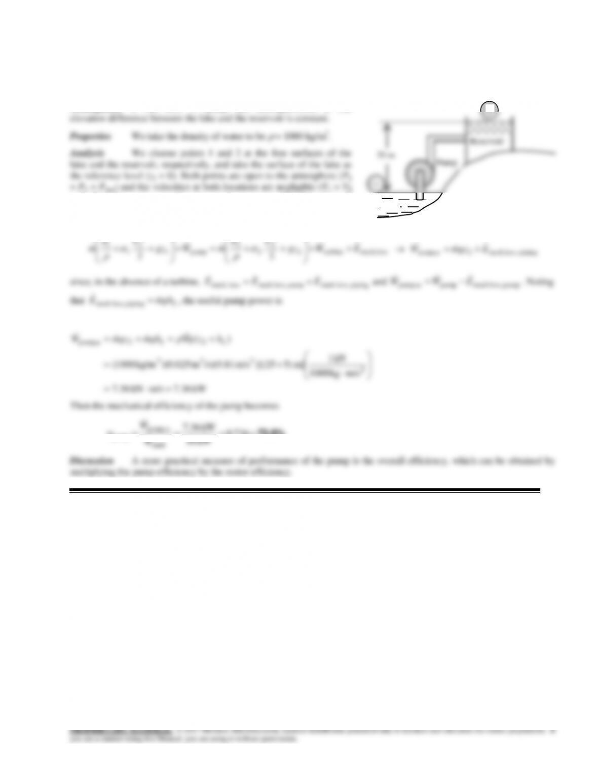
Solution Water is pumped from a large lake to a higher reservoir. The head loss of the piping system is given. The
mechanical efficiency of the pump is to be determined.
Assumptions 1 The flow is steady and incompressible. 2 The
= 0). Then the energy equation for steady incompressible flow through
a control volume between these two points that includes the pump and
the pipes reduces to
lossmech,turbine2
2
2
2
2
pump1
2
1
1
1
22 EWgz
VP
mWgz
VP
m
pipingloss, mech2upump, EgzmW
since, in the absence of a turbine,
pipingloss, mech pumploss, mechloss mech, EEE
and
pumploss, mechpump upump, EWW
. Noting
that
L
ghmE
pipingloss, mech
, the useful pump power is
kW 7.36m/skN 36.7
m/skg 1000
kN 1
m] )525)[(m/s 81.9)(/sm 025.0)(kg/m 1000(
)(
2
233
22upump,
LL hzgghmgzmW V
Then the mechanical efficiency of the pump becomes
73.6% 736.0
kW 10
kW 36.7
shaft
u pump,
pump W
W
Lake
2

12–49
g=9.81 “m/s2″
rho=1000 “kg/m3″
z2=25 “m”
12–36
12–37
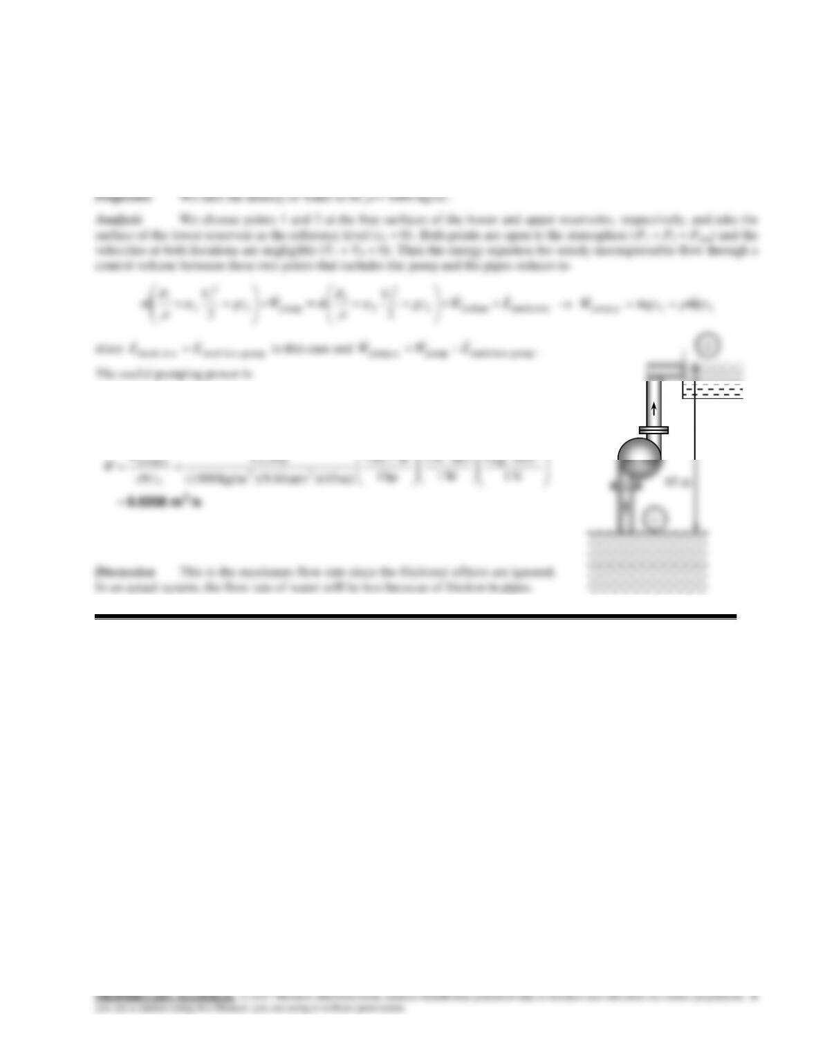
12–50
Solution A pump with a specified shaft power and efficiency is used to raise water to a higher elevation. The
maximum flow rate of water is to be determined.
Assumptions 1 The flow is steady and incompressible. 2 The elevation difference between the reservoirs is constant. 3
We assume the flow in the pipes to be frictionless since the maximum flow rate is to be determined,
.0 pipingloss, mech E
hp 3.12hp) 15)(82.0(
shaft pump,pumpupump, WW
Substituting, the volume flow rate of water is determined to be
N 1
m/skg 1
W1
m/sN 1
hp 1
W7.745
m) )(45m/s )(9.81kg/m (1000
hp 3.12 2
23
2
upump,
gz
W
V
45 m
PUMP
12–51
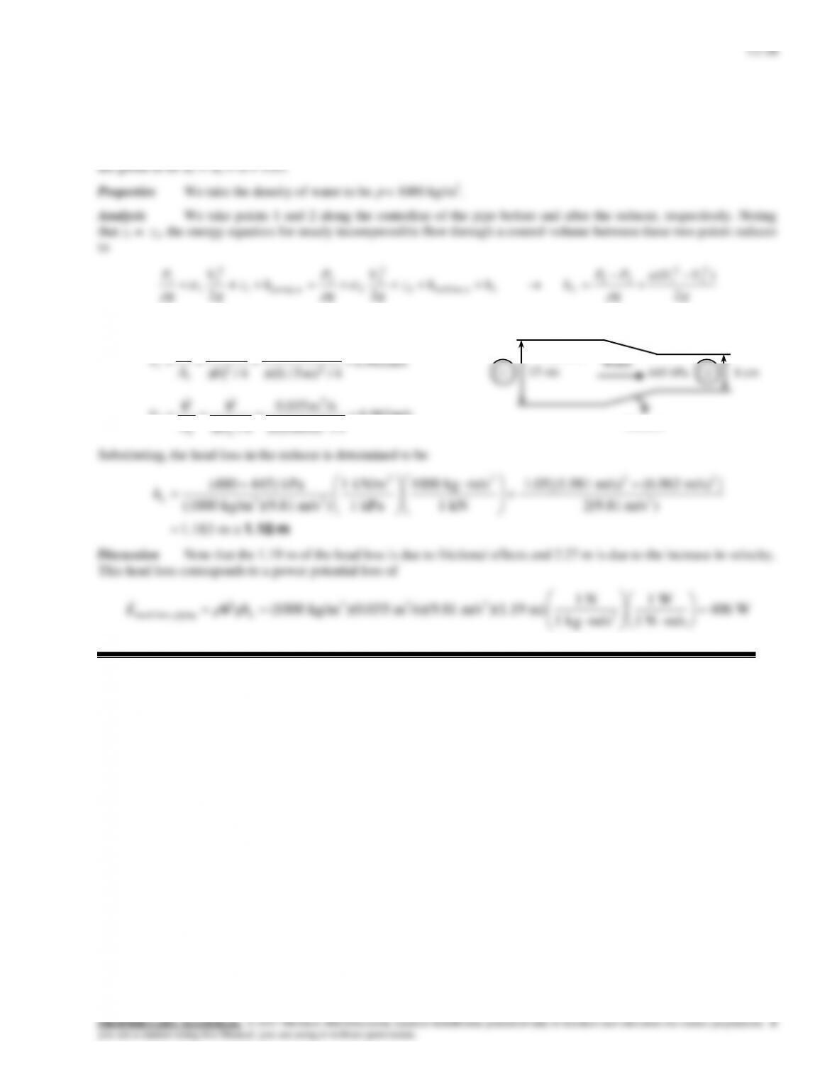
Solution Water flows at a specified rate in a horizontal pipe whose diameter is decreased by a reducer. The pressures
are measured before and after the reducer. The head loss in the reducer is to be determined.
Assumptions 1 The flow is steady and incompressible. 2 The pipe is horizontal. 3 The kinetic energy correction factors
g
g
g
g
22
g
g
where
4/m) (0.15
/sm 035.0
4/ 2
3
2
1
1
D
A
VV
m/s 963.6
4/m) (0.08
/sm 035.0
4/ 2
3
2
2
2
2
D
A
V
VV
mech loss, piping 2
1 kg m/s 1 N m/s
L
15 cm
8 cm
480 kPa
445 kPa
Reducer
1
2
12–39
12–52
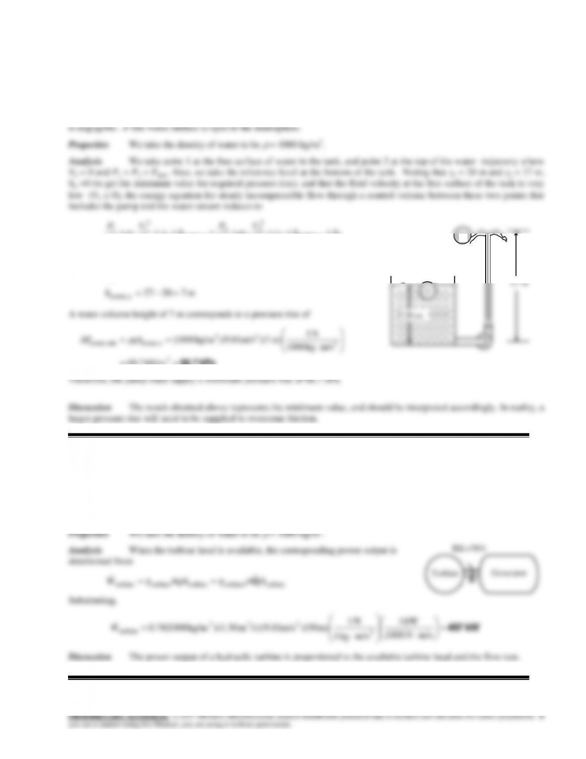
Solution A hose connected to the bottom of a tank is equipped with a nozzle at the end pointing straight up. The
water is pressurized by a pump, and the height of the water jet is measured. The minimum pressure rise supplied by the
pump is to be determined.
Assumptions 1 The flow is steady and incompressible. 2 Friction between the water and air as well as friction in the hose
L
hhz
g
V
g
P
hz
g
V
g
P e turbine,2
2
2
2
2
upump,1
2
1
1
1
22
12 upump, zzh
Substituting,
m 72027
upump, h
A water column height of 7 m corresponds to a pressure rise of
kPa 68.7
2
2
23
upump,min pump,
kN/m7.68
m/s kg1000
N 1
m) 7)(m/s 81.9)( kg/m1000(ghP
Therefore, the pump must supply a minimum pressure rise of 68.7 kPa.
Discussion The result obtained above represents the minimum value, and should be interpreted accordingly. In reality, a
larger pressure rise will need to be supplied to overcome friction.
12–53
Solution The available head of a hydraulic turbine and its overall efficiency are given. The electric power output of
this turbine is to be determined.
Assumptions 1 The flow is steady and incompressible. 2 The available head remains constant.
20 m
27 m
1
2
12–54
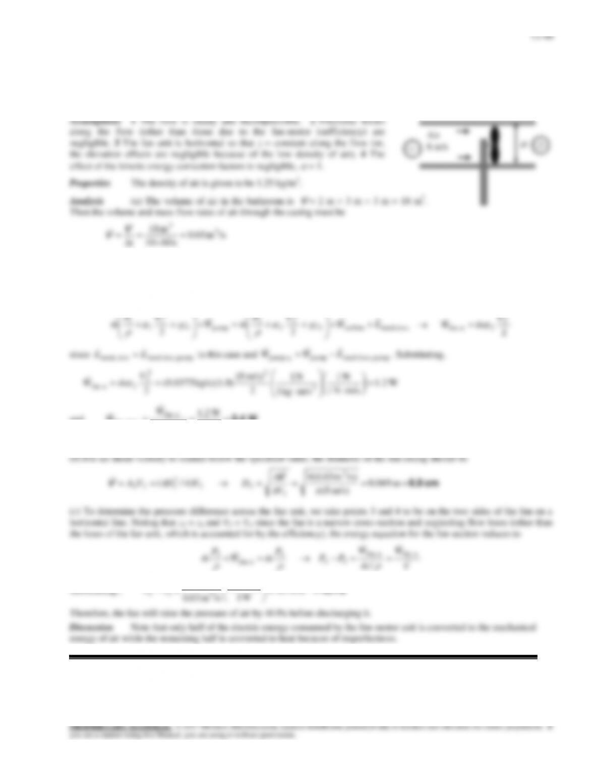
Solution A fan is to ventilate a bathroom by replacing the entire volume of air once every 10 minutes while air
velocity remains below a specified value. The wattage of the fan–motor unit, the diameter of the fan casing, and the pressure
difference across the fan are to be determined.
s 6010
kg/s 0.0375/s)m 03.0)(kg/m 25.1( 33 Vm
We take points 1 and 2 on the inlet and exit sides of the fan, respectively. Point 1 is sufficiently far from the fan so that P 1
= Patm and the flow velocity is negligible (V1 = 0). Also, P2 = Patm. Then the energy equation for this control volume
between the points 1 and 2 reduces to
lossmech,turbine2
2
2
2
2
pump1
2
1
1
1
22 EWgz
VP
mWgz
VP
m
2
2
2
2 ufan,
V
mW
since
pumploss, mechloss mech, EE
in this case and
pumploss, mechpump upump, EWW
. Substituting,
W 2.1
m/sN 1
W 1
m/s kg1
N 1
2
m/s) (8
) kg/s)(1.0(0.0375
22
2
2
2
2 ufan,
V
mW
and
W2.4 0.5
W2.1
motor–fan
u fan,
elect fan,
W
W
Therefore, the electric power rating of the fan/motor unit must be 2.4 W.