Solutions Manual
for
Fundamentals of Thermal Fluid Sciences
5th Edition
Yunus A. Çengel, John M. Cimbala, Robert H. Turner
McGraw-Hill, 2017
Chapter 12
BERNOULLI AND ENERGY EQUATIONS
PROPRIETARY AND CONFIDENTIAL
This Manual is the proprietary property of McGraw-Hill Education and protected by copyright and
other state and federal laws. By opening and using this Manual the user agrees to the following
restrictions, and if the recipient does not agree to these restrictions, the Manual should be promptly
returned unopened to McGraw-Hill Education: This Manual is being provided only to authorized
professors and instructors for use in preparing for the classes using the affiliated textbook. No
other use or distribution of this Manual is permitted. This Manual may not be sold and may not
be distributed to or used by any student or other third party. No part of this Manual may be
reproduced, displayed or distributed in any form or by any means, electronic or otherwise,
without the prior written permission of McGraw-Hill Education.
12-2
Bernoulli Equation
12-1C
Solution We are to define stagnation pressure and discuss how it can be measured.
12-2C
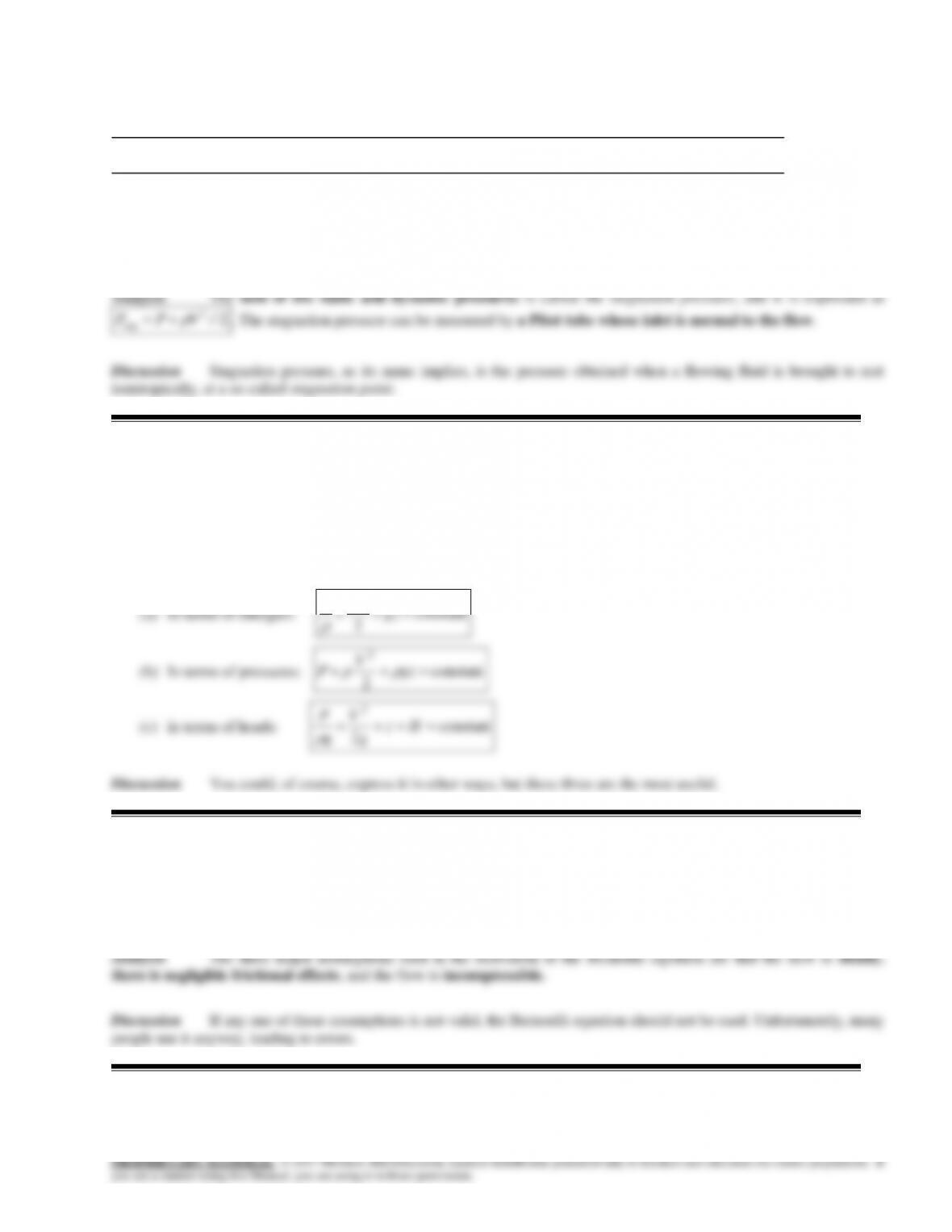
Solution We are to express the Bernoulli equation in three different ways.
Analysis The Bernoulli equation is expressed in three different ways as follows:
2
VP
12-4C
Solution We are to define and discuss static, dynamic, and hydrostatic pressure.
Analysis Static pressure P is the actual pressure of the fluid. Dynamic pressure
V 2/2 is the pressure rise when
12-5C
Solution We are to define streamwise acceleration and discuss how it differs from normal acceleration.
12-6C
Solution We are to define and discuss pressure head, velocity head, and elevation head.
12-4
12-7C
Solution We are to explain how and why a siphon works, and its limitations.
12-8C
Solution We are to discuss the hydraulic grade line in open-channel flow and at the outlet of a pipe.
12-9C
Solution We are to discuss the effect of liquid density on the operation of a siphon.
12–10C
Solution We are to define hydraulic grade line and compare it to energy grade line.
12–11C
Solution We are to discuss and compare the operation of a manometer.
Analysis As the duct converges to a smaller cross-sectional area, the velocity increases. By Bernoulli’s equation, the
12–12C
Solution We are to discuss and compare two different types of manometer arrangements in a flow.
Analysis Arrangement 1 consists of a Pitot probe that measures the stagnation pressure at the pipe centerline, along
12–13C
Solution We are to discuss the maximum rise of a jet of water from a tank.
12-6
12–14C
Solution We are to compare siphoning at sea level and on a mountain.
12–15
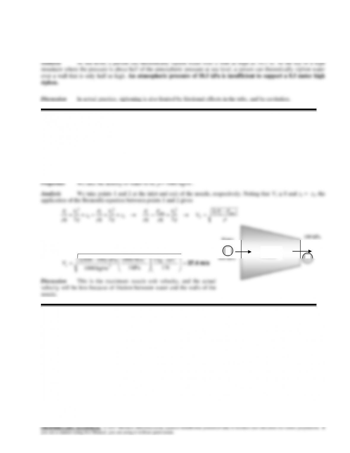
Solution In a power plant, water enters the nozzles of a hydraulic turbine at a specified pressure. The maximum
velocity water can be accelerated to by the nozzles is to be determined.
Assumptions 1The flow of water is steady, incompressible, and irrotational with negligible frictional effects (so that the
Bernoulli equation is applicable). 2 Water enters the nozzle with a low velocity.
Substituting the given values, the nozzle exit velocity is determined to be
m/s 37.4
N 1
m/skg 1
kPa 1
N/m 1000
kg/m 1000
kPa )100800(2 22
3
1
V
Discussion This is the maximum nozzle exit velocity, and the actual
velocity will be less because of friction between water and the walls of the
nozzle.
800 kPa
Turbine
nozzzle
V
1
2
12–16
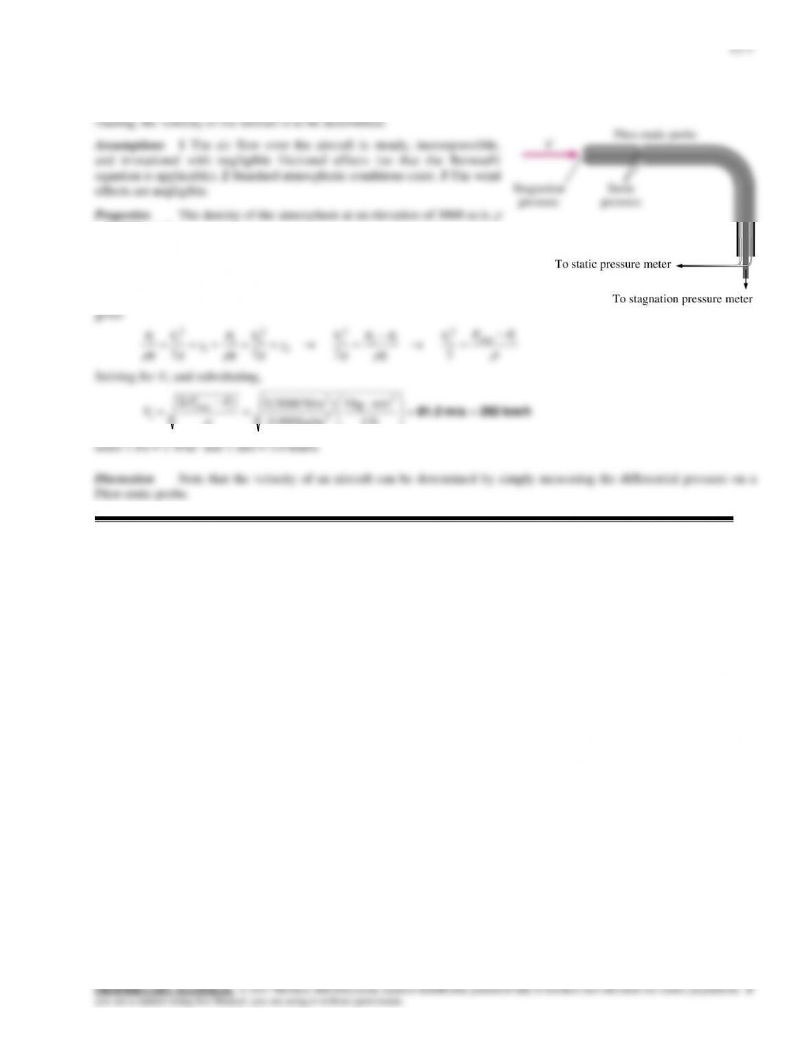
Solution The velocity of an aircraft is to be measured by a Pitot-static probe. For a given differential pressure
= 0.909 kg/m3.
Analysis We take point 1 at the entrance of the tube whose opening is
parallel to flow, and point 2 at the entrance of the tube whose entrance is
normal to flow. Noting that point 2 is a stagnation point and thus V2 = 0 and
z1 = z2, the application of the Bernoulli equation between points 1 and 2
12-8
12–17
Solution A Pitot-static probe is inserted into the duct of an air heating system parallel to flow, and the differential
height of the water column is measured. The flow velocity and the pressure rise at the tip of the Pitot-static probe are to be
determined.
Assumptions 1 The flow through the duct is steady, incompressible, and irrotational with negligible frictional effects (so
air
g
g
g
g
g
g
g
2
22
2
1
where the pressure rise at the tip of the Pitot-static probe is
Pa 235
2
2
23
12
N/m 235
m/s kg1
N 1
m) 024.0)(m/s 81.9)( kg/m1000( ghPP w
Also,
3
3kg/m 074.1
)K 27345)(K/kgmkPa 287.0(
kPa 98
RT
P
air
Substituting,
m/s 20.9
N 1
m/skg 1
kg/m 1.074
)N/m 235(2 2
3
2
1
V
Discussion Note that the flow velocity in a pipe or duct can be measured easily by a Pitot-static probe by inserting the
V
h=2.4 cm
Air
2
1
12–18E
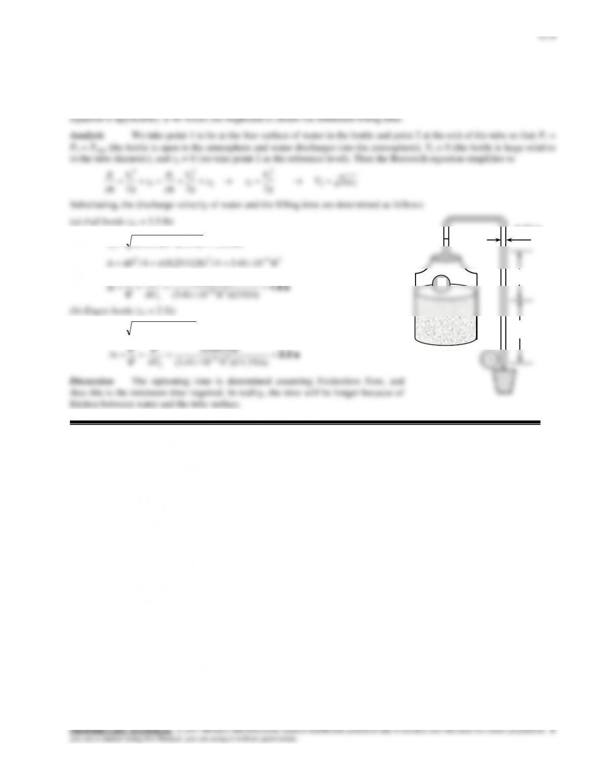
Solution The drinking water needs of an office are met by large water bottles with a plastic hose inserted in it. The
minimum filling time of an 8-oz glass is to be determined when the bottle is full and when it is near empty.
Assumptions 1 The flow is steady, incompressible, and irrotational with negligible frictional effects (so that the Bernoulli
ft/s 0.15ft) 5.3)(ft/s 2.32(2 2
2V
2422 ft 1041.34/ft) 12/25.0(4/
0.25 in
12–19
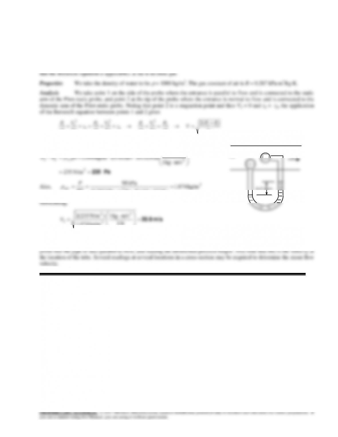
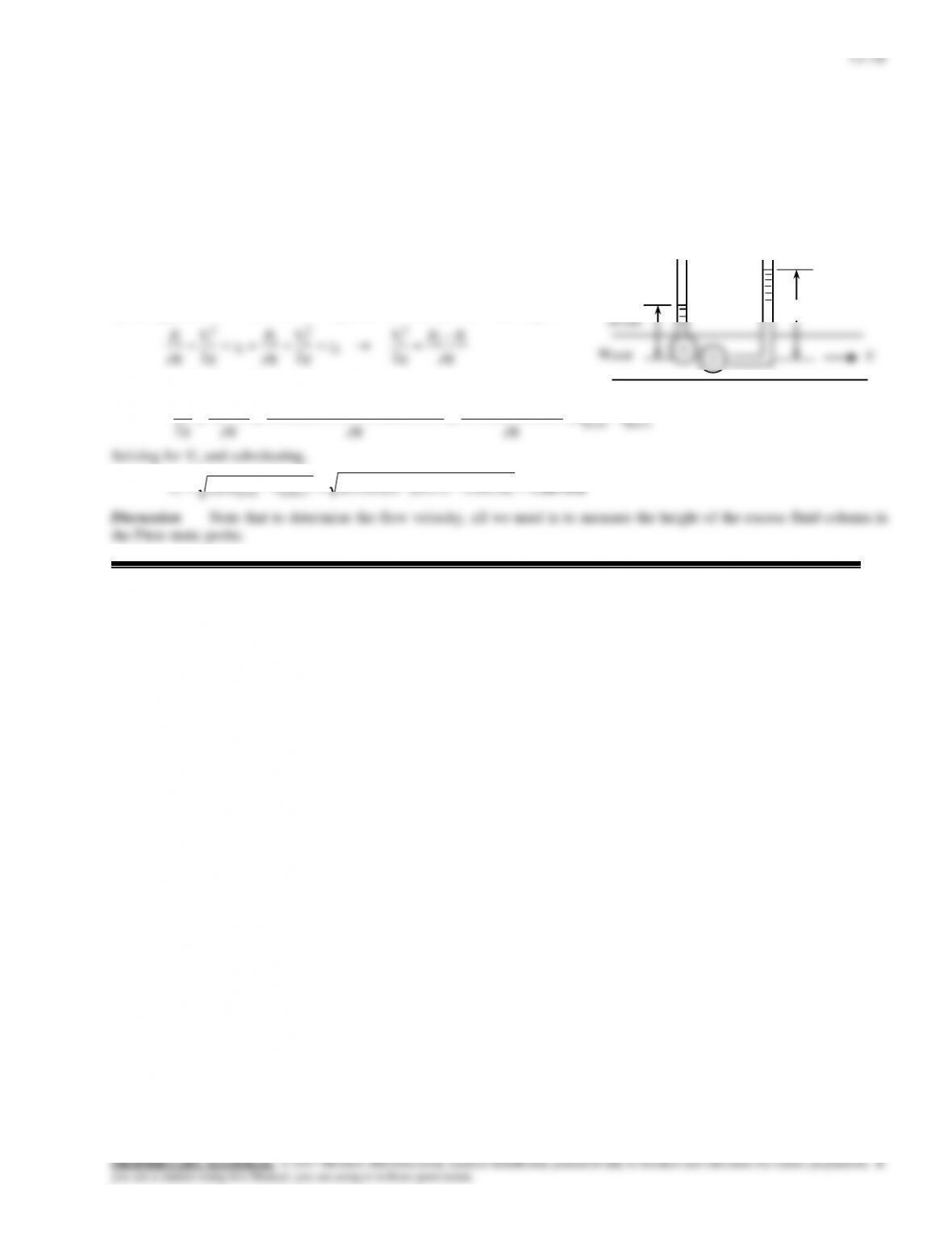
Solution The static and stagnation pressures in a horizontal pipe are measured. The velocity at the center of the pipe
is to be determined.
Assumptions The flow is steady, incompressible, and irrotational with negligible frictional effects in the short distance
between the two pressure measurement locations (so that the Bernoulli equation is applicable).
Analysis We take points 1 and 2 along the centerline of the pipe, with point 1 directly under the piezometer and
point 2 at the entrance of the Pitot-static probe (the stagnation point).
This is a steady flow with straight and parallel streamlines, and thus the
static pressure at any point is equal to the hydrostatic pressure at that
point. Noting that point 2 is a stagnation point and thus V2 = 0 and z1 =
z2, the application of the Bernoulli equation between points 1 and 2 gives
g
PP
g
V
g
V
g
P
g
V
g
P
12
2
1
2
2
22
1
2
11
2
22
Substituting the P1 and P2 expressions give
piezopitot
piezopitotpiezopitot
12
2
1)()()(
2hh
g
hhg
g
RhgRhg
g
PP
g
V
m/s 1.33 m] )26.035.0)[(m/s 81.9(2)(2 2
piezopitot1 hhgV
26 cm
35 cm
Water
V
1
2
12–11
12–20
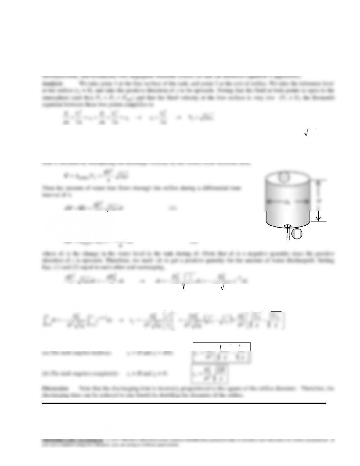
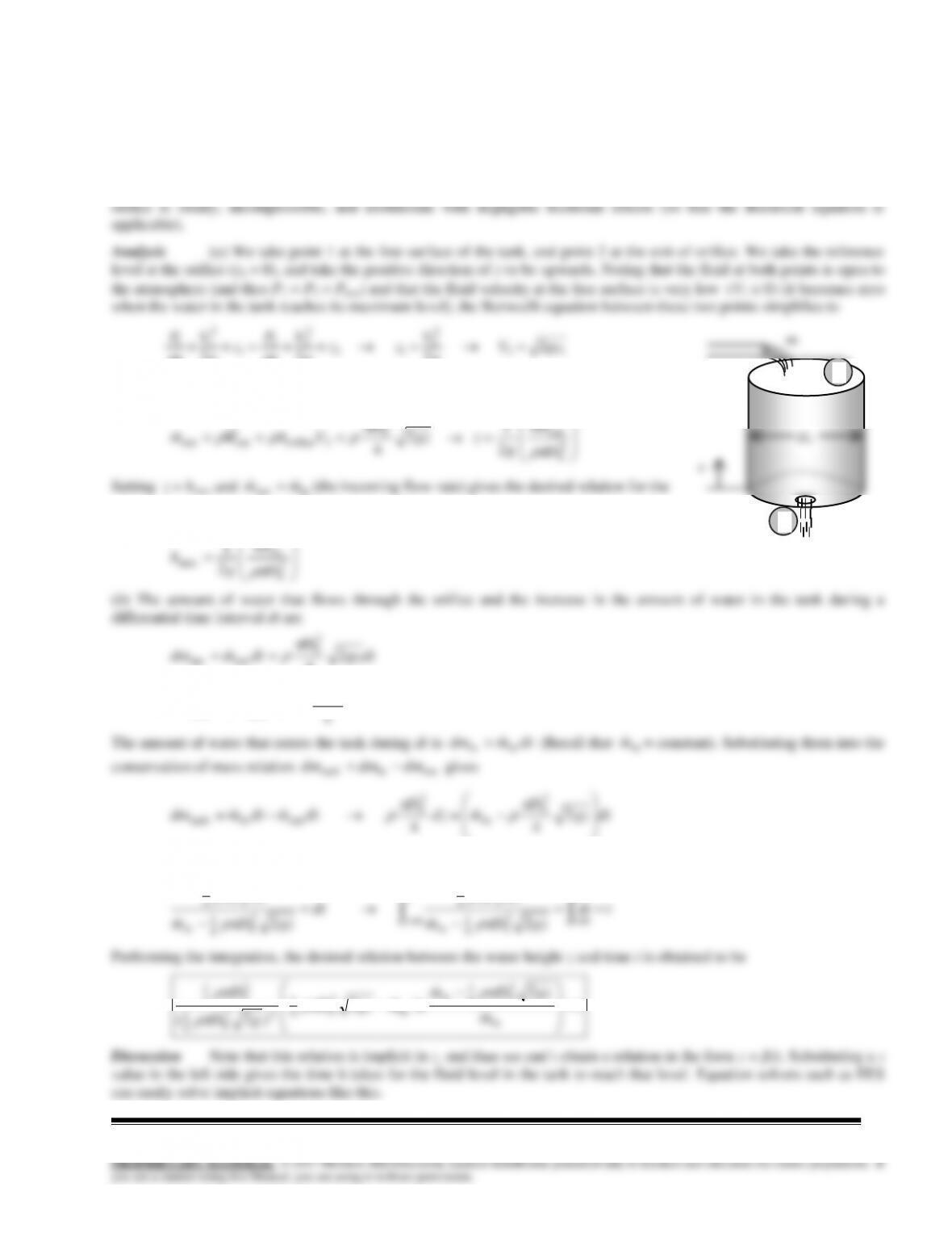
Solution A water tank of diameter Do and height H open to the atmosphere is initially filled with water. An orifice of
diameter D with a smooth entrance (no losses) at the bottom drains to the atmosphere. Relations are to be developed for the
time required for the tank to empty completely and half-way.
Assumptions 1 The orifice has a smooth entrance, and thus the frictional losses are negligible. 2 The flow is steady,
12
12
1
2
22 gzV
g
g
g
g
g
For generality, we express the water height in the tank at any time t by z, and the discharge velocity by
gzV2
2
. Note
that water surface in the tank moves down as the tank drains, and thus z is a variable whose value changes from H at the
beginning to 0 when the tank is emptied completely.
We denote the diameter of the orifice by D, and the diameter of the tank by Do. The flow rate of water from the
12–21E
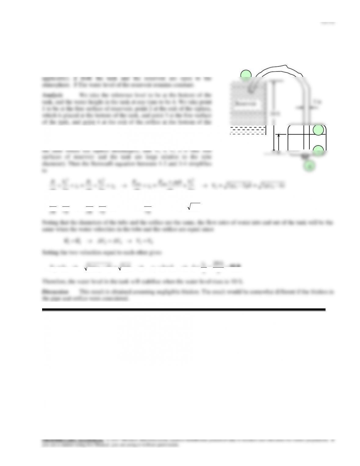
Solution A siphon pumps water from a large reservoir to a lower tank which is initially empty. Water leaves the tank
through an orifice. The height the water will rise in the tank at equilibrium is to be determined.
Assumptions 1 The flow is steady, incompressible, and irrotational
with negligible frictional effects (so that the Bernoulli equation is
tank. Then z1 = 20 ft, z2 = z4 = 0, z3 = h, P1 = P3 = P4 = Patm (the
reservoir is open to the atmosphere and water discharges into the
atmosphere) P2 = Patm+gh (the hydrostatic pressure at the bottom of
4
h
Water
Tank
1
3
12–13
12–22
Solution Water enters an empty tank steadily at a specified rate. An orifice at the bottom allows water to escape.
The maximum water level in the tank is to be determined, and a relation for water height z as a function of time is to be
obtained.
Assumptions 1 The orifice has a smooth entrance, and thus the frictional losses are negligible. 2 The flow through the
12–23E
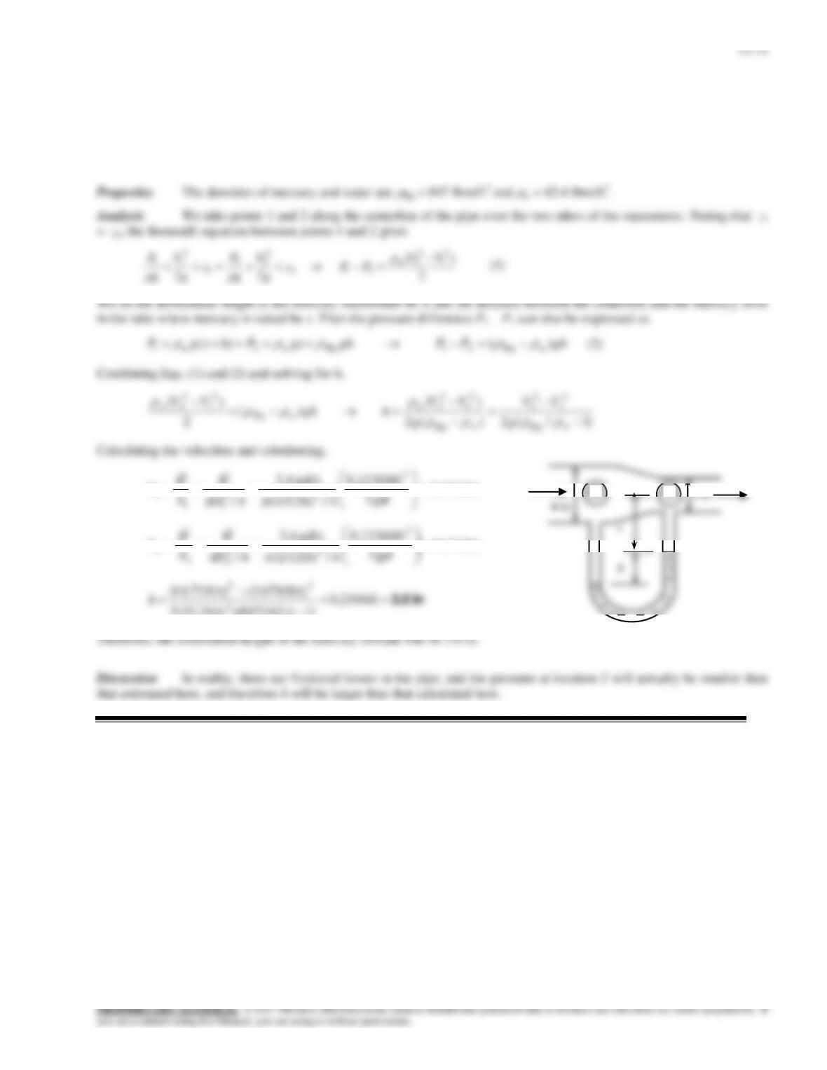
Solution Water flows through a horizontal pipe that consists of two sections at a specified rate. The differential
height of a mercury manometer placed between the two pipe sections is to be determined.
Assumptions 1The flow through the pipe is steady, incompressible, and irrotational with negligible frictional effects (so
that the Bernoulli equation is applicable). 2 The losses in the reducing section are negligible.
ft/s 676.3
gal 1
ft 0.13368
4/ft) (4/12
gal/s 4.2
4/
3
22
1
1
1
D
A
V
VV
ft/s 71.14
gal 1
ft 0.13368
4/ft) (2/12
gal/s 4.2
4/
3
22
2
2
2
D
A
V
VV
in 3.0
ft 2504.0
)14.62/847)(ft/s 2(32.2
)ft/s 676.3(ft/s) 71.14(
2
22
h
Therefore, the differential height of the mercury column will be 3.0 in.
Discussion In reality, there are frictional losses in the pipe, and the pressure at location 2 will actually be smaller than
that estimated here, and therefore h will be larger than that calculated here.
2 in
s
h
4 in
2
1
12–15
12–24
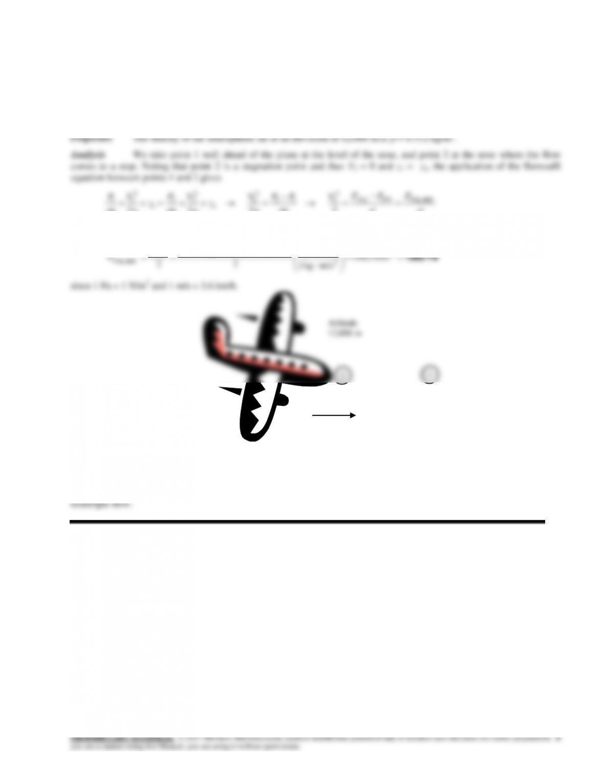
Solution An airplane is flying at a certain altitude at a given speed. The pressure on the stagnation point on the nose
of the plane is to be determined, and the approach to be used at high velocities is to be discussed.
Assumptions 1 The air flow over the aircraft is steady, incompressible, and irrotational with negligible frictional effects
(so that the Bernoulli equation is applicable). 2 Standard atmospheric conditions exist. 3 The wind effects are negligible.
2
1
2
2
22
g
g
g
g
g
g
Solving for Pstag, gage and substituting,
23
2
1
N 1
m/s) 6.3/300)(kg/m 312.0(
V
12–25
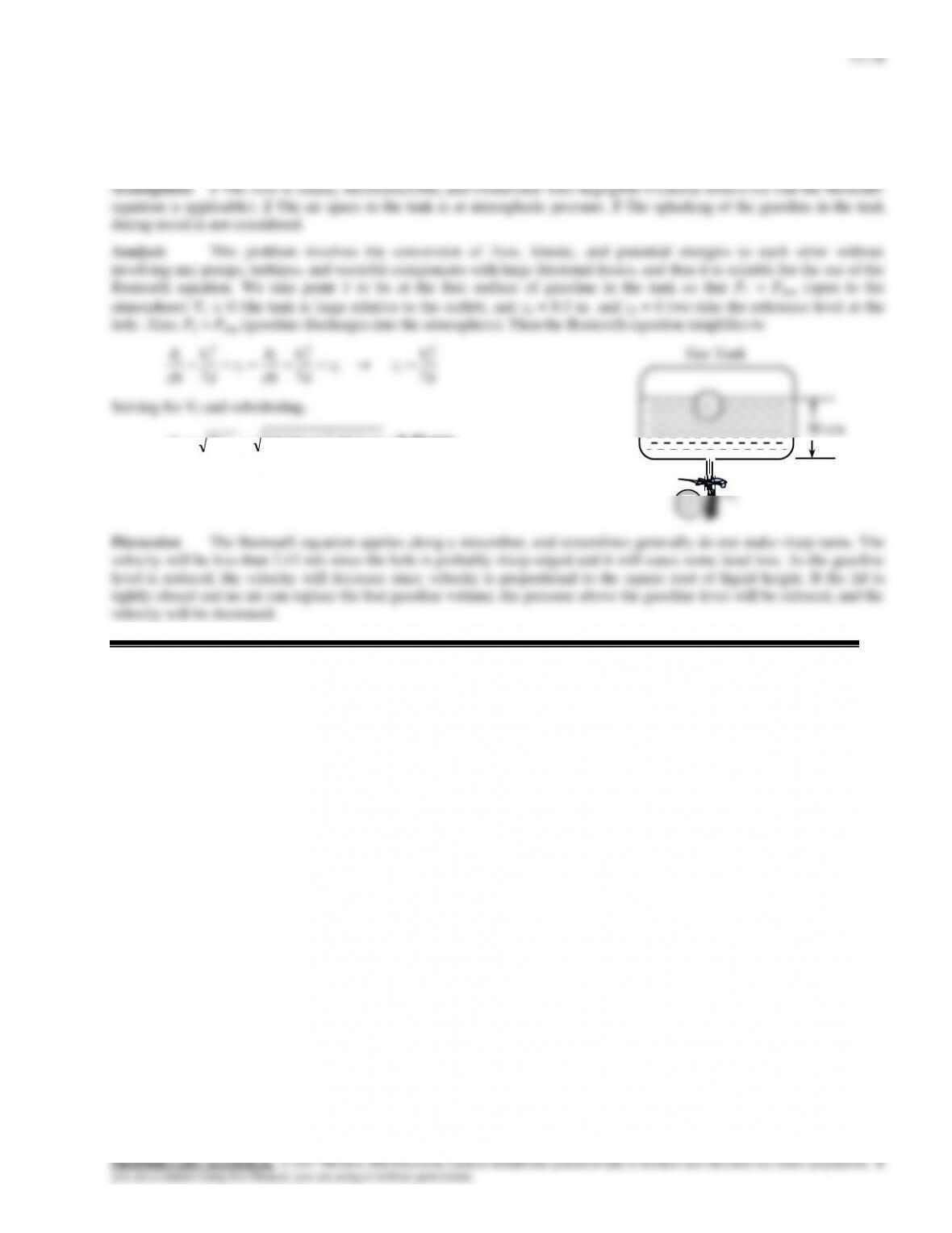
Solution The bottom of a car hits a sharp rock and a small hole develops at the bottom of its gas tank. For a given
height of gasoline, the initial velocity of the gasoline out of the hole is to be determined. Also, the variation of velocity with
time and the effect of the tightness of the lid on flow rate are to be discussed.
m/s 2.43 m) 3.0)(m/s 81.9(22 2
12 gzV
Therefore, the gasoline will initially leave the tank with a velocity of 2.43 m/s.
30 cm
12–17
12–26
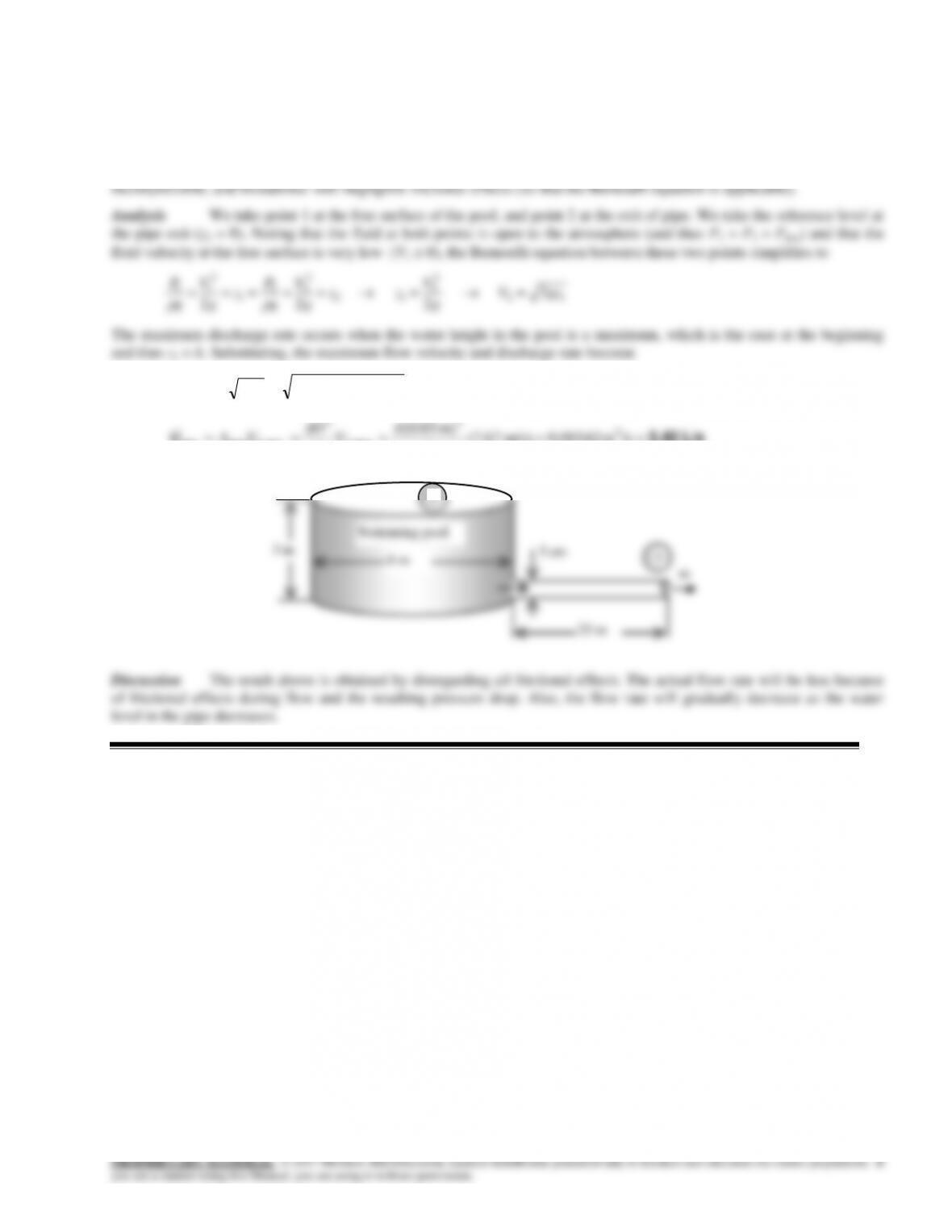
Solution The water in an above the ground swimming pool is to be emptied by unplugging the orifice of a horizontal
pipe attached to the bottom of the pool. The maximum discharge rate of water is to be determined.
Assumptions 1 The orifice has a smooth entrance, and all frictional losses are negligible. 2 The flow is steady,
m/s 67.7m) 3)(m/s 81.9(22 2
max,2 ghV
L/s 5.42 /sm 0.00542m/s) 67.7(
4
m) 03.0(
4
3
2
max,2
2
max,2pipemax
V
D
VA
V
12–27
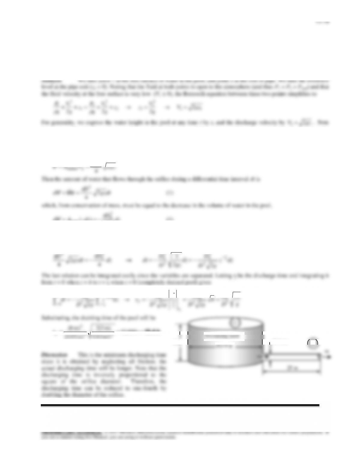
Solution The water in an above the ground swimming pool is to be emptied by unplugging the orifice of a horizontal
pipe attached to the bottom of the pool. The time it will take to empty the tank is to be determined.
Assumptions 1 The orifice has a smooth entrance, and all frictional losses are negligible. 2 The flow is steady,
incompressible, and irrotational with negligible frictional effects (so that the Bernoulli equation is applicable).
2
that water surface in the pool moves down as the pool drains, and thus z is a variable whose value changes from h at the
beginning to 0 when the pool is emptied completely.
We denote the diameter of the orifice by D, and the diameter of the pool by Do. The flow rate of water from the pool is
obtained by multiplying the discharge velocity by the orifice cross-sectional area,
D
2
dz
D
dzAd 4
)(
2
0
tank
V
(2)
where dz is the change in the water level in the pool during dt. (Note that dz is a negative quantity since the positive
direction of z is upwards. Therefore, we used –dz to get a positive quantity for the amount of water discharged). Setting
Eqs. (1) and (2) equal to each other and rearranging,
dzz
gD
D
dz
gz
D
D
dtdz
D
dtgz
D2
1
2
2
1
4
2
42
2
0
2
2
0
2
0
2
The last relation can be integrated easily since the variables are separated. Letting tf be the discharge time and integrating it
from t = 0 when z = h to t = tf when z = 0 (completely drained pool) gives
g
h
D
D
h
gD
Dz
gD
D
tdzz
gD
D
dt
z
f
zz
t
t
f2
2
2
2
–
2
2
2
0
2
2
0
0
2
1
2
2
0
02/1
2
2
0
0
1
2
1
1
Substituting, the draining time of the pool will be
h 15.4 s 600,55
m/s 81.9
m) 3(2
)m 03.0(
m) 8(
22
2
f
t
m
3 m
Swimming pool
D=3 cm
1
2
12–19
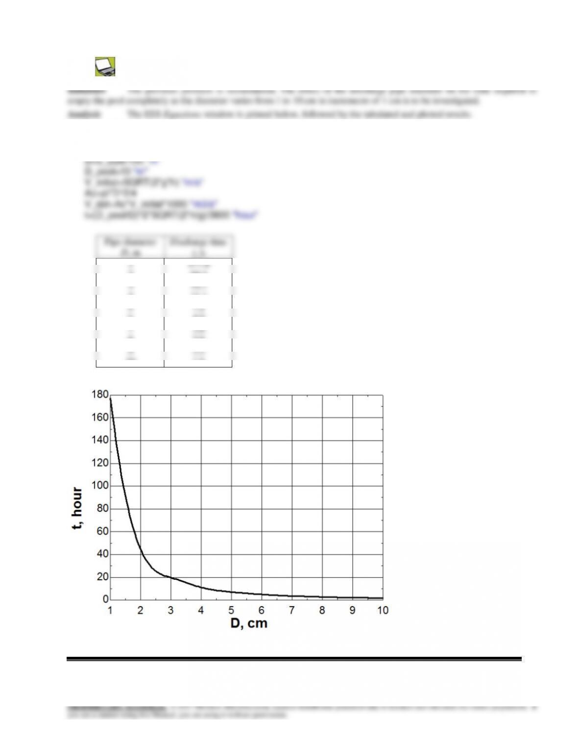
12–28
g=9.81 “m/s2″
rho=1000 “kg/m3″
h=2 “m”
12–29
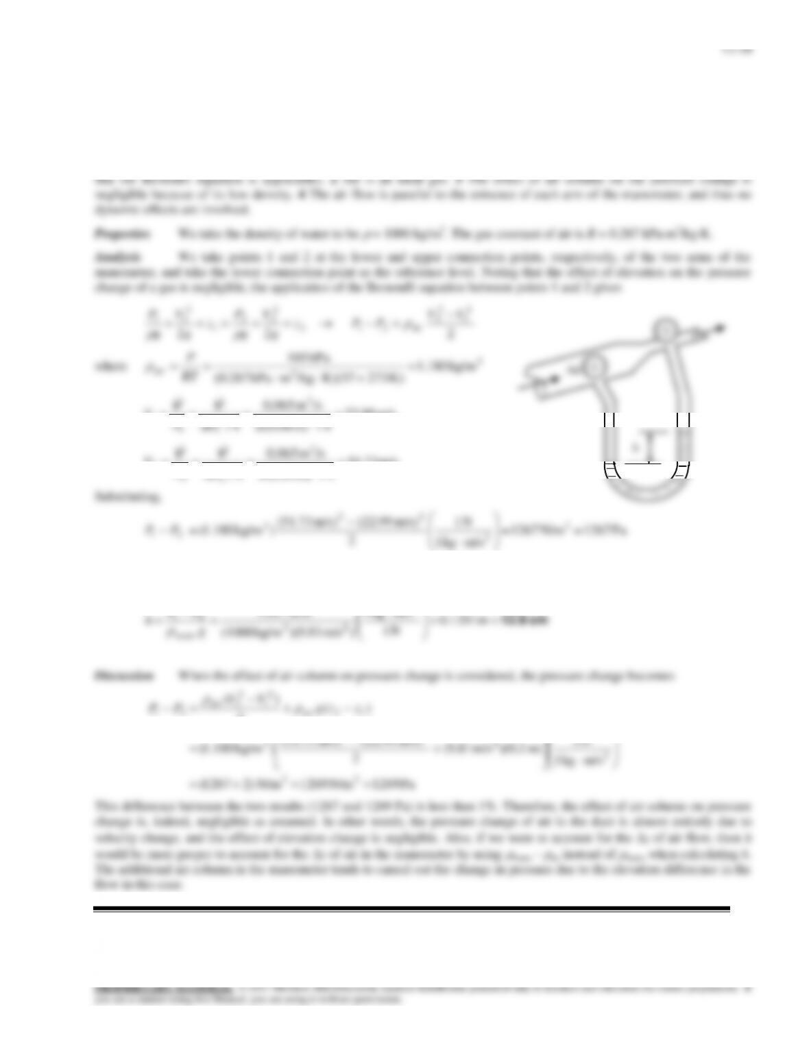
Solution Air flows upward at a specified rate through an inclined pipe whose diameter is reduced through a reducer.
The differential height between fluid levels of the two arms of a water manometer attached across the reducer is to be
determined.
Assumptions 1 The flow through the duct is steady, incompressible and irrotational with negligible frictional effects (so
3kg/m 180.1
)K 27337)(K/kgmkPa 287.0(
m/s 99.22
4/m) (0.06
/sm 065.0
4/ 2
3
2
1
1
1
D
A
V
VV
m/s 73.51
4/m) (0.04
/sm 065.0
4/ 2
3
2
2
2
2
D
A
V
VV
m/skg 1
2
2
The differential height of water in the manometer corresponding to this pressure change is determined from
ghPwater
to be
cm 12.9
m 1291.0
N 1
m/skg 1
)m/s 81.9)(kg/m (1000
N/m 1267 2
23
2
21
g
PP
h
water
Discussion When the effect of air column on pressure change is considered, the pressure change becomes
Pa 1269N/m 1269N/m )21267(
m/skg 1
N 1
m) 2.0)(m/s 81.9(
2
m/s) 99.22(m/s) 73.51(
)kg/m 1.180(
)(
2
)(
22
2
2
22
3
12
2
1
2
2
21
zzg
VV
PP air
air
This difference between the two results (1267 and 1269 Pa) is less than 1%. Therefore, the effect of air column on pressure
change is, indeed, negligible as assumed. In other words, the pressure change of air in the duct is almost entirely due to
velocity change, and the effect of elevation change is negligible. Also, if we were to account for the z of air flow, then it
would be more proper to account for the z of air in the manometer by using
water –
air instead of
water when calculating h.
The additional air column in the manometer tends to cancel out the change in pressure due to the elevation difference in the
flow in this case.
h
Air