PROBLEM 16.164
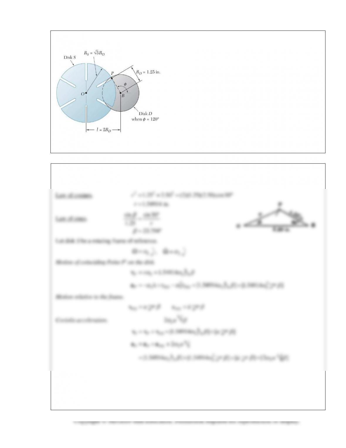
The Geneva mechanism shown is used to provide an intermit-
tent rotary motion of disk S. Disk D weighs 2 lb and has a
radius of gyration of 0.9 in. and disk S weighs 6 lb and has a
radius of gyration of 1.5 in. The motion of the system is
controlled by a couple M applied to disk D. A pin P is attached
to disk D and can slide in one of the six equally spaced slots
cut in disk S. It is desirable that the angular velocity of disk S
be zero as the pin enters and leaves each of the six slots; this
will occur if the distance between the centers of the disks and
the radii of the disks are related as shown. Knowing disk D
rotates with a constant counterclockwise angular velocity of 8
rad/s and the friction between the slot and pin P is negligible,
determine when
φ
= 150° (a) the couple M, (b) the magnitude
of the force pin P applies to disk S.
SOLUTION
Geometry:
222
PROBLEM 16.164 (Continued)
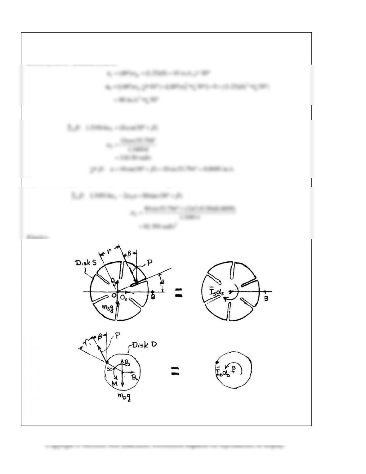
Motion of disk D. (rotation about B)
Equate the two expressions for
P
v
and resolve into components.
: 1.54914 10cos(30 )
βω β
= °+
Equate the two expressions for
P
a
and resolve into components.
: 1.54914 2 80sin (30 )
u
β aω β
− = °+
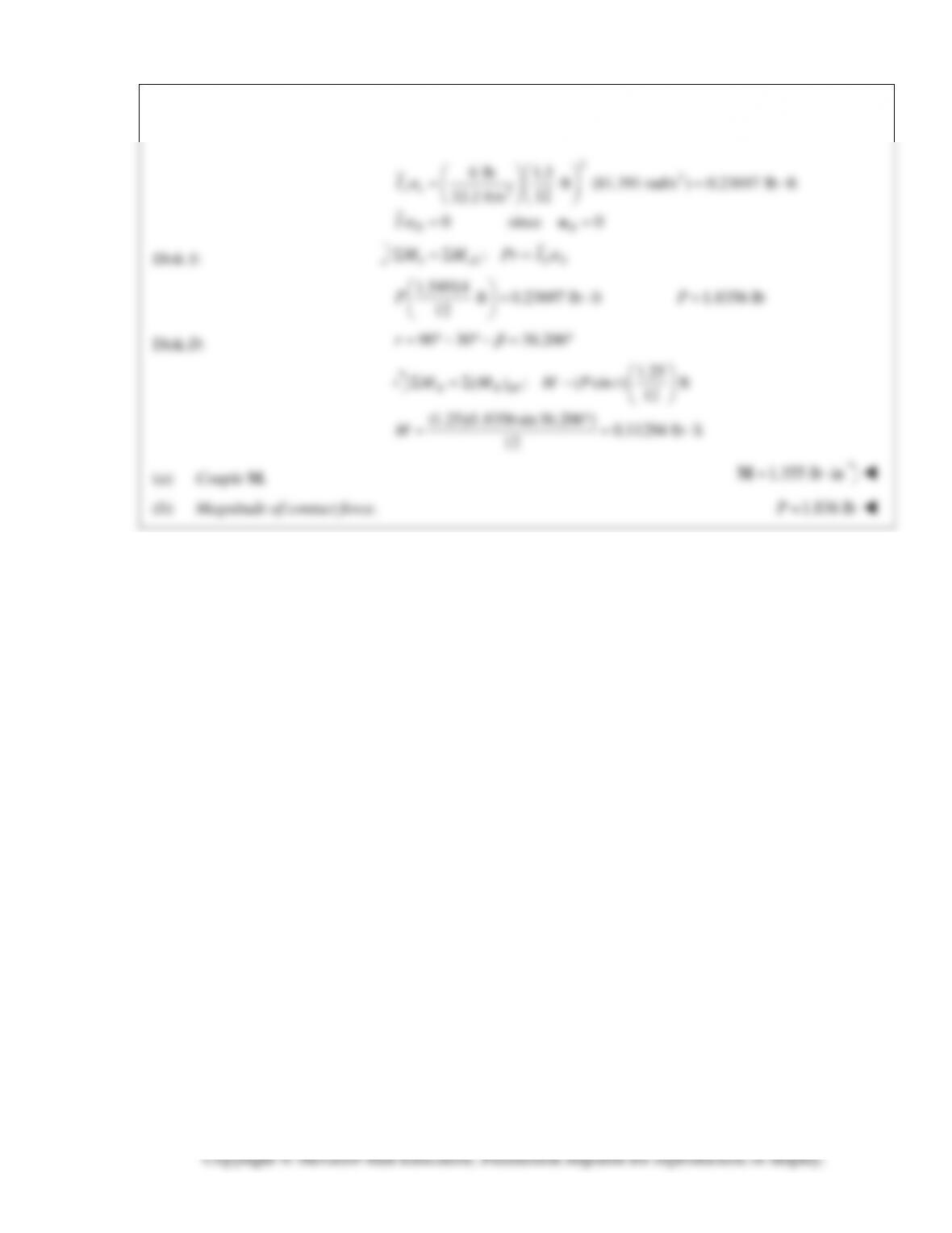
Kinetics:
PROBLEM 16.164 (Continued)
PROBLEM 16.CQ1
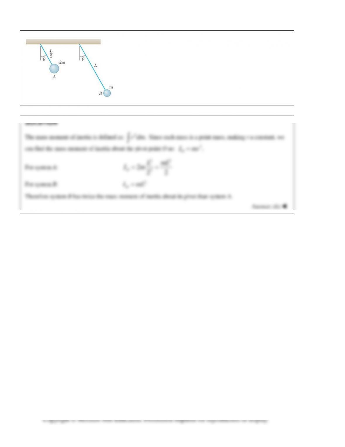
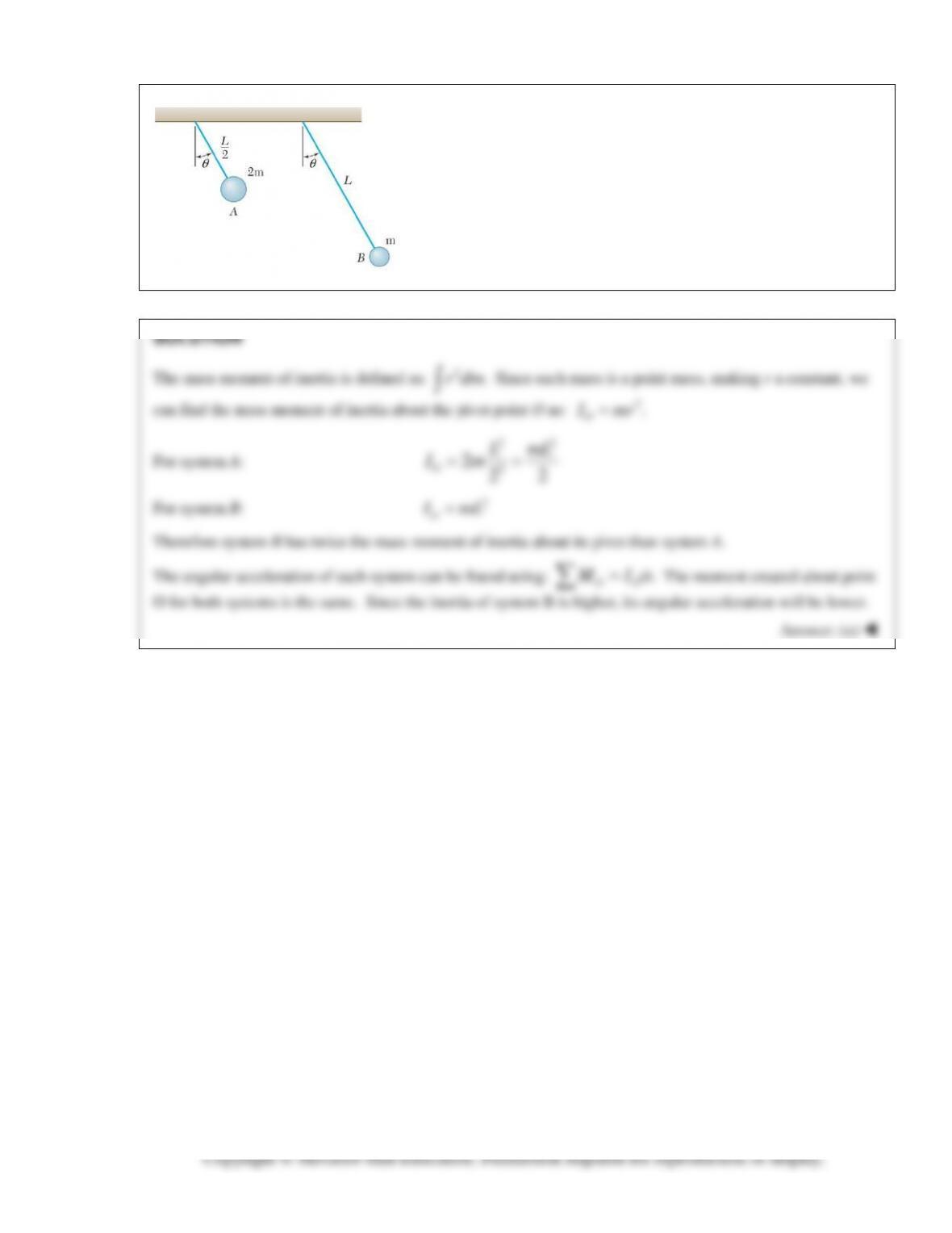
Two pendulums, A and B, with the masses and lengths shown are
released from rest. Which system has a larger mass moment of inertia
about its pivot point?
(a) A
(b) B
(c) They are the same.
PROBLEM 16.CQ2
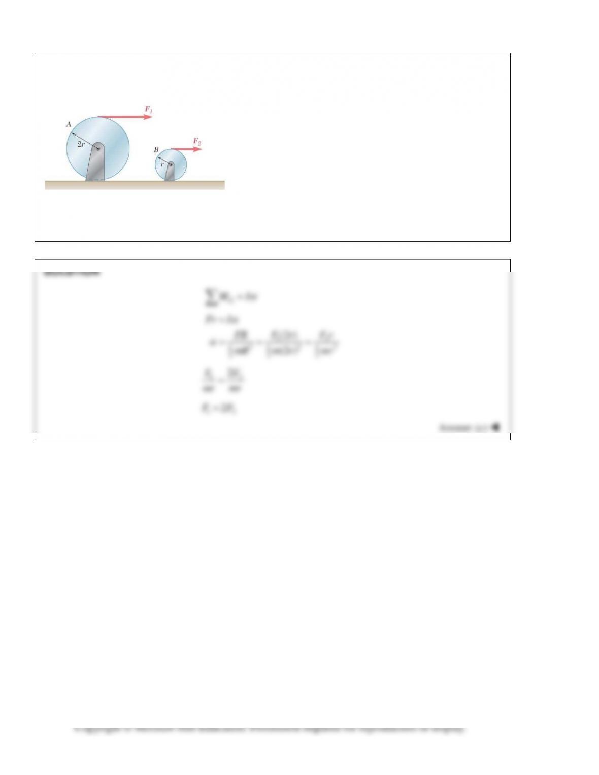
Two pendulums, A and B, with the masses and lengths shown are
released from rest. Which system has a larger angular acceleration
immediately after release?
(a) A
(b) B
(c) They are the same.
PROBLEM 16.CQ3
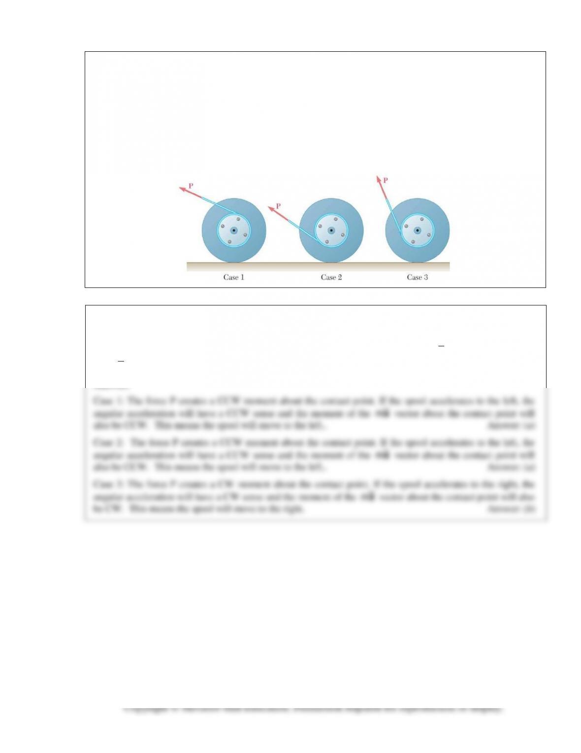
Two solid cylinders, A and B, have the same mass m and the
radii 2r and r respectively. Each is accelerated from rest with a
force applied as shown. In order to impart identical angular
accelerations to both cylinders, what is the relationship
between F1 and F2?
(a) F1 = 0.5F2
(b) F1 = F2
(c) F1 = 2F2
(d) F1 = 4F2
(e) F1 = 8F2
PROBLEM 16.CQ4
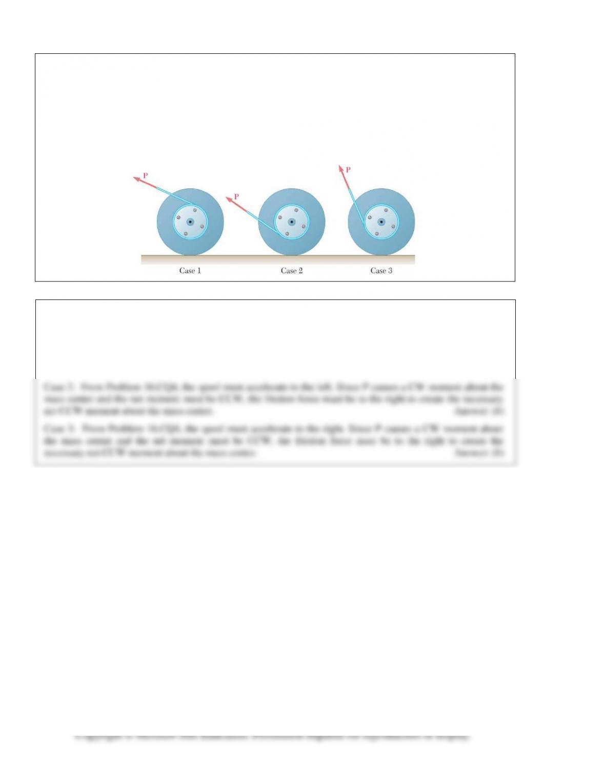
A cord is attached to a spool when a force P is applied to the cord as shown. Assuming the spool rolls without
slipping, what direction does the spool move for each case?
Case 1: (a) left (b) right (c) It would not move.
Case 2: (a) left (b) right (c) It would not move.
Case 3: (a) left (b) right (c) It would not move.
SOLUTION
For each case consider that the force P creates a moment about the point where the spool contacts the ground.
This moment must have the same sense (CW or CCW) as the resultant of the couple
Ia
plus the moment of
the
ma
vector about the contact point.
Answer:
ma
ma
PROBLEM 16.CQ5
A cord is attached to a spool when a force P is applied to the cord as shown. Assuming the spool rolls without
slipping, in what direction does the friction force act for each case?
Case 2: (a) left (b) right (c) The friction force would be zero.
Case 3: (a) left (b) right (c) The friction force would be zero.
SOLUTION
The direction of the friction force on a rolling object is not determined exclusively by the direction of rolling.
To determine the direction of the friction force, consider all forces acting on the body and note that the sum of
the forces must be in the same direction as the acceleration of the mass center and that the sum of the
moments about the mass center must have the same sense as the angular acceleration.
PROBLEM 16.CQ6
A front wheel drive car starts from rest and accelerates to the right. Knowing that the tires do not slip on the
road, what is the direction of the friction force the road applies to the front tires?
(a) left
(b) right
(c) The friction force is zero.
PROBLEM 16.CQ7
A front wheel drive car starts from rest and accelerates to the right. Knowing that the tires do not slip on the
road, what is the direction of the friction force the road applies to the rear tires?
(a) left
(b) right
(c) The friction force is zero.
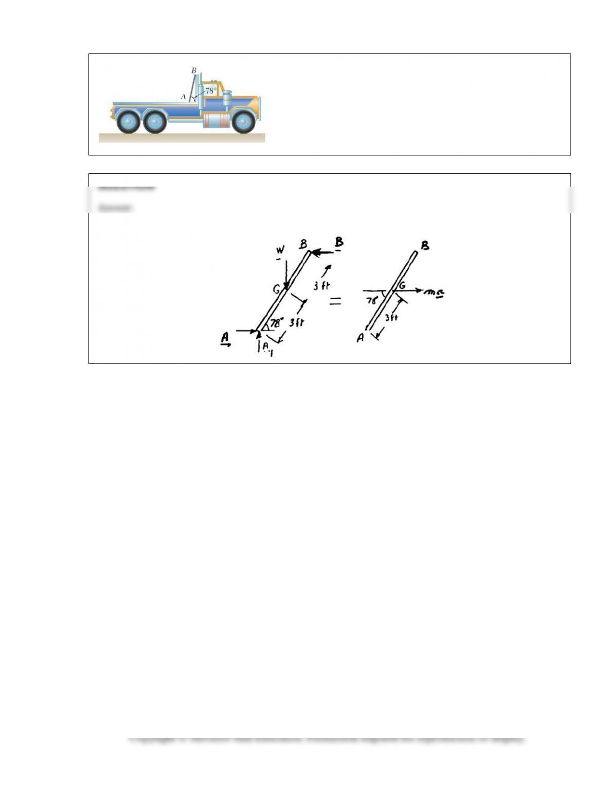
PROBLEM 16.F1
A 6–ft board is placed in a truck with one end resting against a
block secured to the floor and the other leaning against a vertical
partition. Draw the FBD and KD necessary to determine the
maximum allowable acceleration of the truck if the board is to
remain in the position shown.
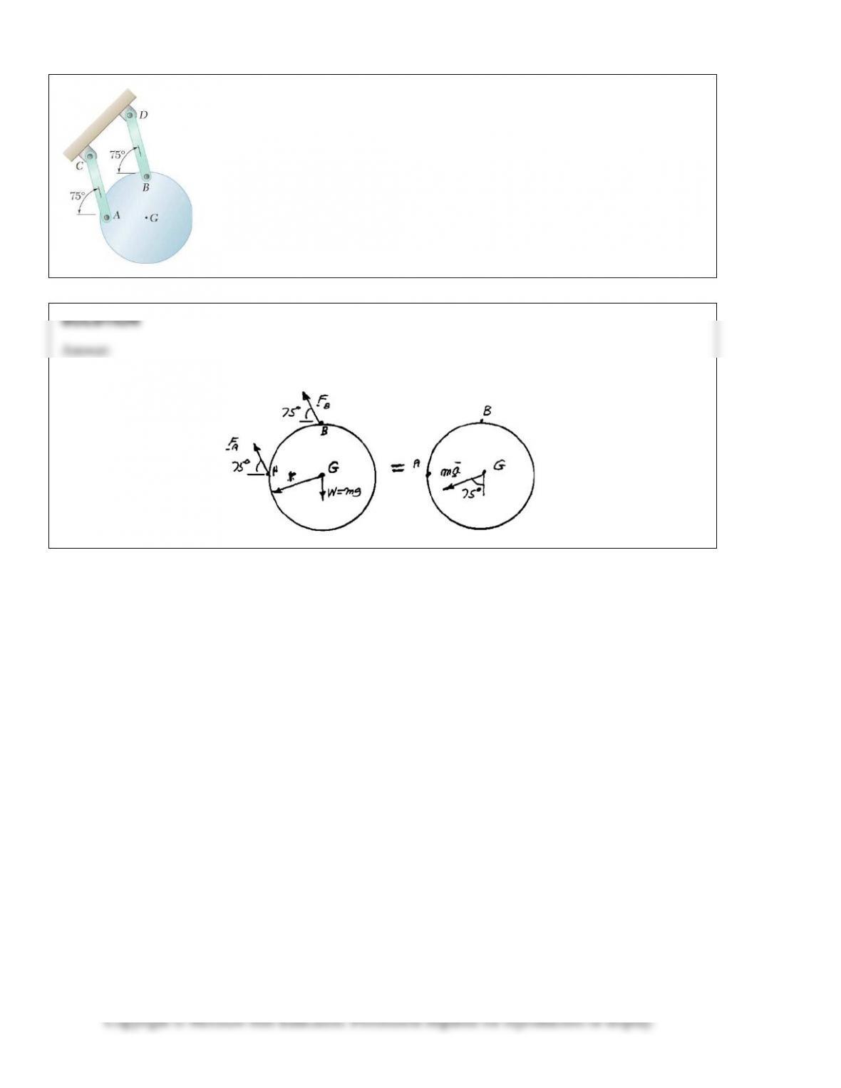
PROBLEM 16.F2
A uniform circular plate of mass 3 kg is attached to two links AC and BD of the
same length. Knowing that the plate is released from rest in the position shown, in
which lines joining G to A and B are, respectively, horizontal and vertical, draw the
FBD and KD for the plate.
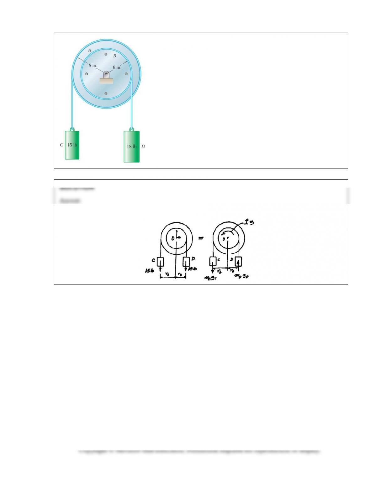
PROBLEM 16.F3
Two uniform disks and two cylinders are assembled as indicated. Disk
A weighs 20 lb and disk B weighs 12 lb. Knowing that the system is
released from rest, draw the FBD and KD for the whole system.
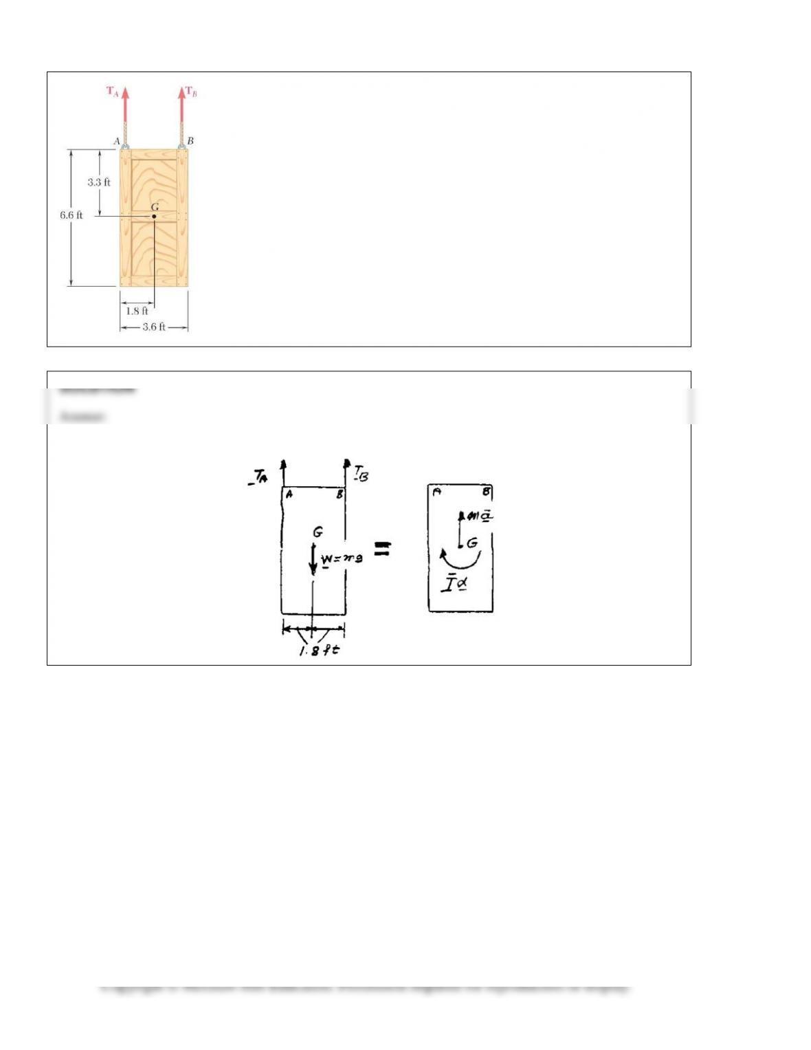
PROBLEM 16.F4
The 400-lb crate shown is lowered by means of two overhead cranes. Knowing
the tension in each cable, draw the FBD and KD that can be used to determine
the angular acceleration of the crate and the acceleration of the center of gravity.
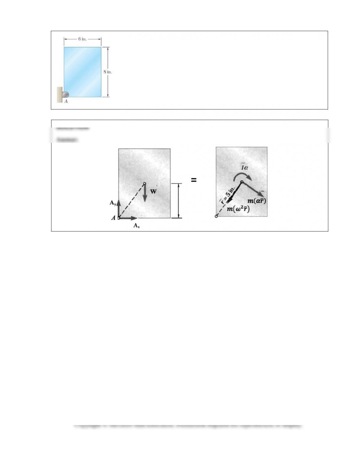
PROBLEM 16.F5
A uniform 6 × 8-in. rectangular plate of mass m is pinned at A. Knowing the
angular velocity of the plate at the instant shown is
ω
, draw the FBD and KD.
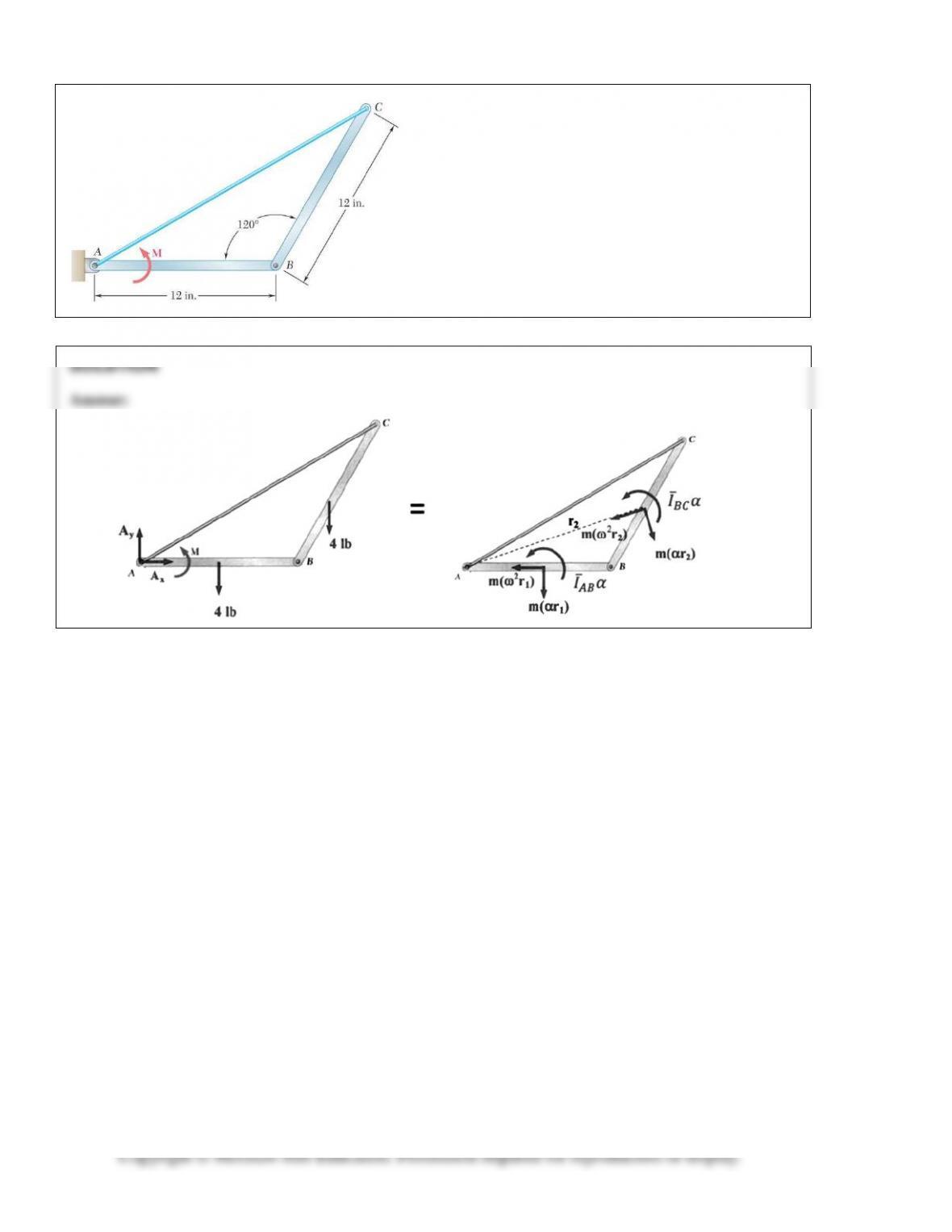
PROBLEM 16.F6
Two identical 4–lb slender rods AB and BC are
connected by a pin at B and by the cord AC. The
assembly rotates in a vertical plane under the combined
effect of gravity and a couple M applied to rod AB.
Knowing that in the position shown the angular velocity
of the assembly is
ω
, draw the FBD and KD that can be
used to determine the angular acceleration of the
assembly and the tension in cord AC.
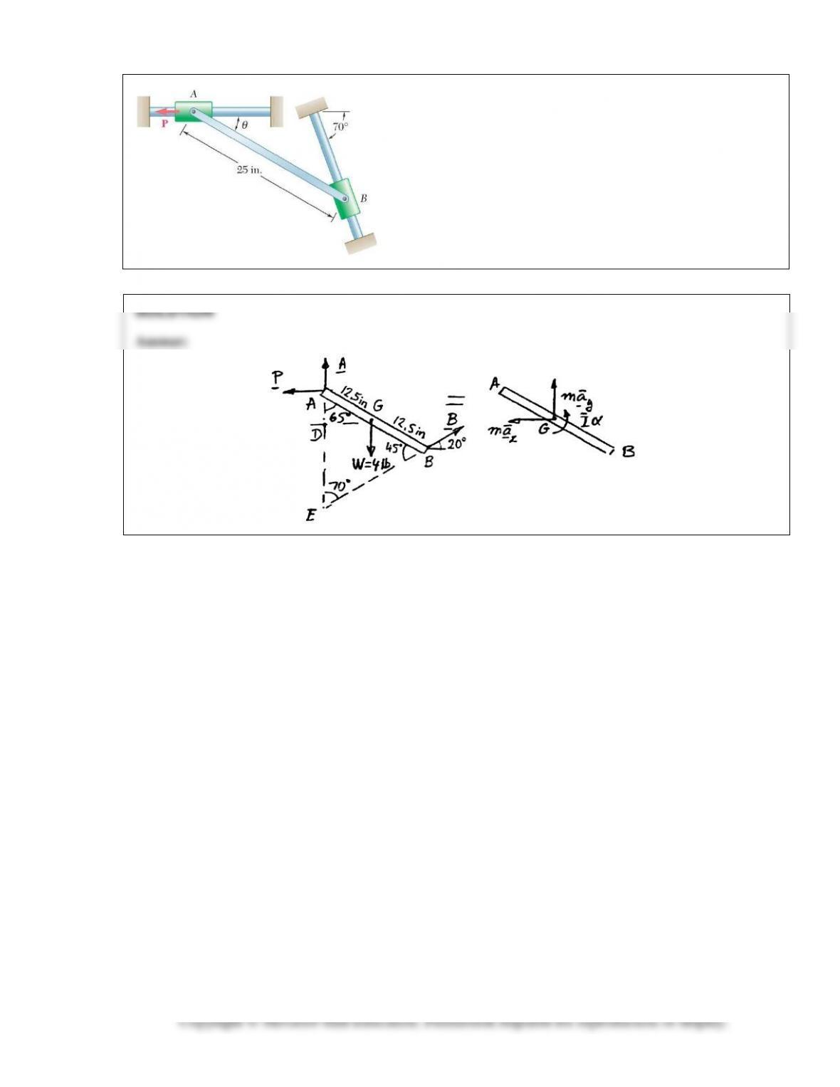
PROBLEM 16.F7
The 4–lb uniform rod AB is attached to collars of negligible mass
which may slide without friction along the fixed rods shown.
Rod AB is at rest in the position
θ
= 25° when a horizontal force
P is applied to collar A causing it to start moving to the left.
Draw the FBD and KD for the rod.
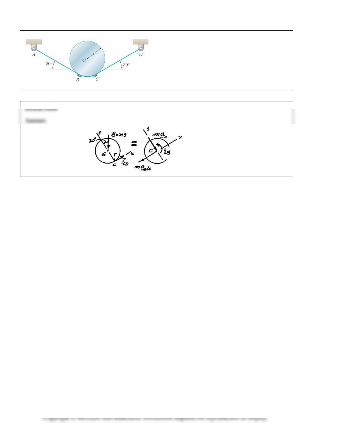
PROBLEM 16.F8
A uniform disk of mass m = 4 kg and radius r = 150 mm
is supported by a belt ABCD that is bolted to the disk at
B and C. If the belt suddenly breaks at a point located
between A and B, draw the FBD and KD for the disk
immediately after the break.