Unlock document.
This document is partially blurred.
Unlock all pages and 1 million more documents.
Get Access
8-21
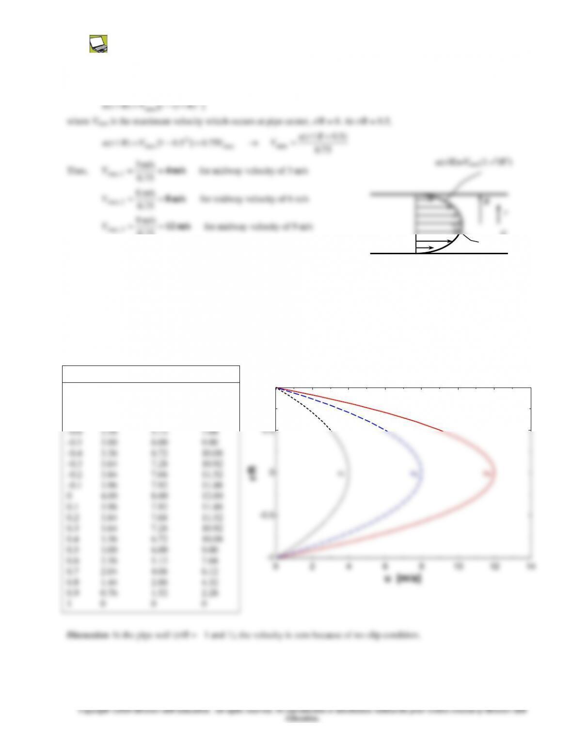
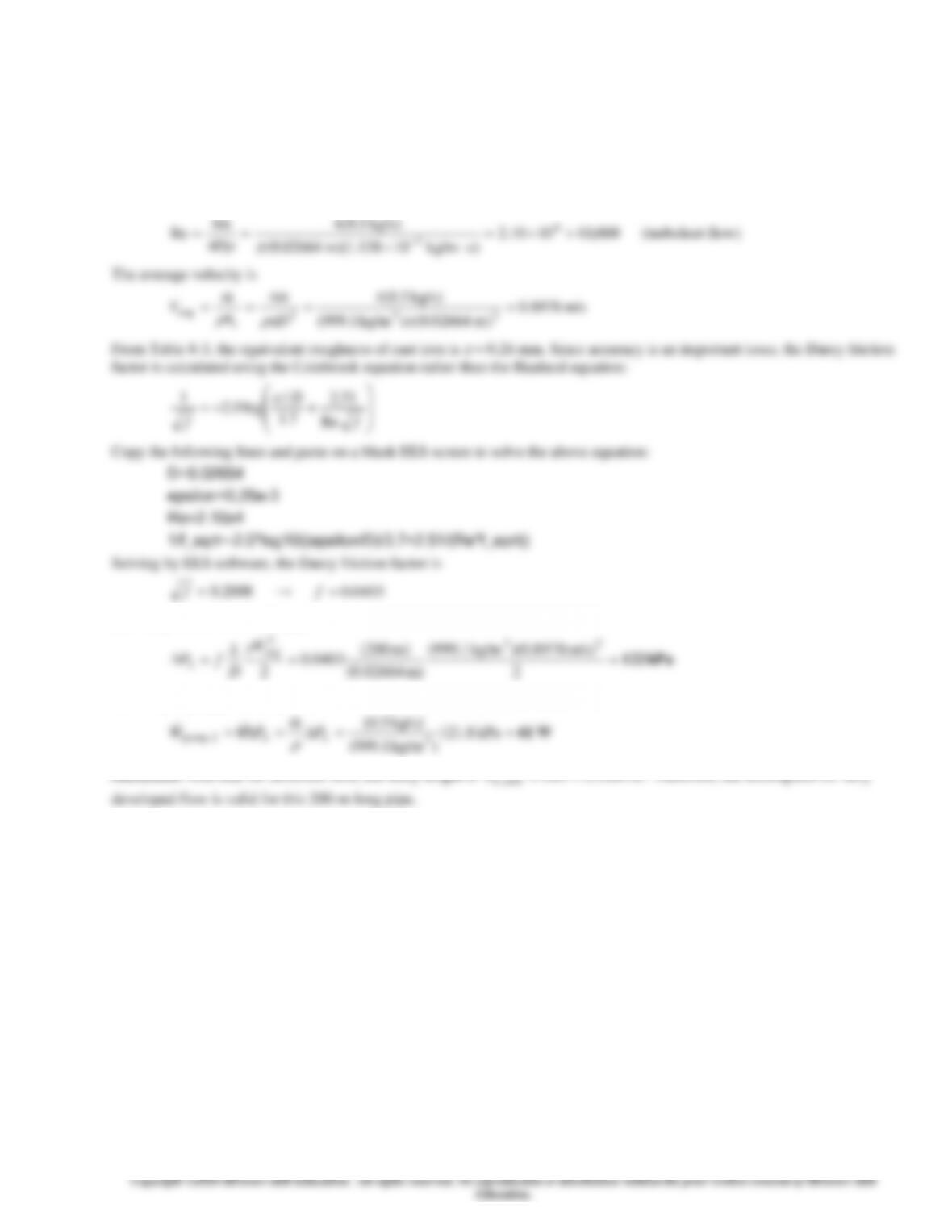
8-43 In fully developed laminar flow inside a circular pipe, the velocities at r/R = 0.5 are measured. For each measured
velocity, (a) the maximum velocity is to be determined, and (b) the velocity profile is to be plotted.
Assumptions The flow is steady, laminar, and fully developed.
Analysis (a) The velocity profile in fully developed laminar flow in a circular pipe is given by
(b) The problem is solved using EES, and the solution is given below
"GIVEN"
V_midway_1=3 [m/s] "u(r = R/2) = 3 m/s"
V_midway_2=6 [m/s] "u(r = R/2) = 6 m/s"
V_midway_3=9 [m/s] "u(r = R/2) = 9 m/s"
"ANALYSIS"
u_1=4/3*V_midway_1*(1-r_ratio^2)
u_2=4/3*V_midway_2*(1-r_ratio^2)
u_3=4/3*V_midway_3*(1-r_ratio^2)
r/R u1 [m/s] u2 [m/s] u3 [m/s]
-1 0 0 0
-0.9 0.76 1.52 2.28
-0.8 1.44 2.88 4.32
-0.7 2.04 4.08 6.12
-0.6 2.56 5.12 7.68
-0.5 3.00 6.00 9.00
-0.4 3.36 6.72 10.08
-0.3 3.64 7.28 10.92
-0.2 3.84 7.68 11.52
-0.1 3.96 7.92 11.88
0 4.00 8.00 12.00
0.1 3.96 7.92 11.88
0.2 3.84 7.68 11.52
0.3 3.64 7.28 10.92
0.4 3.36 6.72 10.08
0.5 3.00 6.00 9.00
0
Vmax
-1
-0.5
0
0.5
1
r/R
u1u2u3
8-22
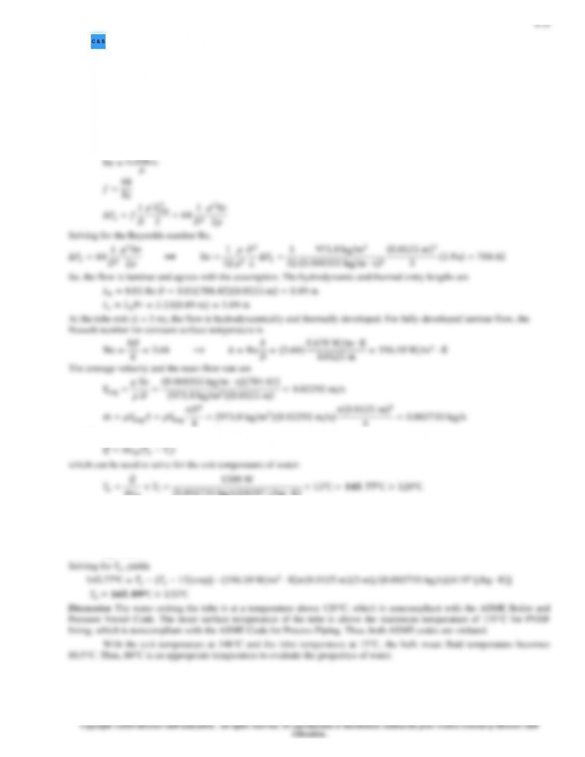
8-44 Water flowing in fully developed conditions through a tube, (a) the maximum velocity of the flow in the tube and (b)
the pressure gradient for the flow are to be determined.
Assumptions 1 Steady operating conditions exist. 2 Properties are constant. 3 Flow is isothermal.
Properties The properties of water at 15°C are
= 999.1 kg/m3 and
= 1.138 10−3 kg/m∙s (from Table A-9).
Analysis The Reynolds number of the flow is
)kg/s 02.0(44
avg =
m
DV
8-24
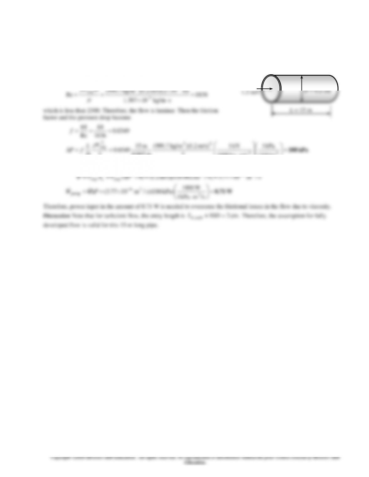
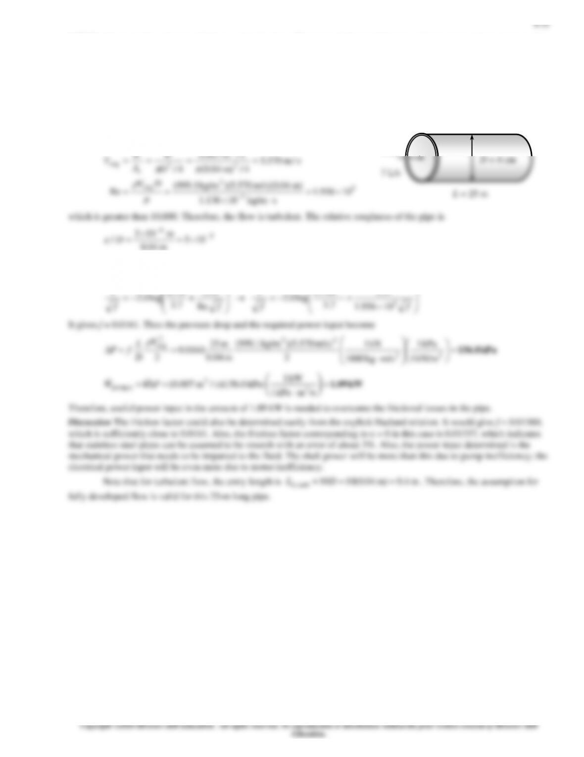
8-46 The average flow velocity in a pipe is given. The pressure drop and the pumping power are to be determined.
Assumptions 1 The flow is steady and incompressible. 2 The entrance effects are negligible, and thus the flow is fully
developed. 3 The pipe involves no components such as bends, valves, and connectors. 4 The piping section involves no work
devices such as pumps and turbines.
Properties The density and dynamic viscosity of water are given to be = 999.7 kg/m3 and = 1.30710-3 kg/ms,
respectively.
Analysis (a) First we need to determine the flow regime. The Reynolds
number of the flow is
1836
skg/m 10307.1
m) 10m/s)(2 2.1)(kg/m 7.999(
Re 3-
-33
avg =
==
DV
which is less than 2300. Therefore, the flow is laminar. Then the friction
factor and the pressure drop become
kPa 188=
==
===
22
23
2
avg
kN/m 1
kPa 1
m/skg 1000
kN 1
2
m/s) 2.1)(kg/m 7.999(
m 0.002
m 15
0349.0
2
0349.0
1836
64
Re
64
V
D
L
fP
f
(b) The volume flow rate and the pumping power requirements are
====
−
/m 1077.3]4/m) (0.002m/s)[ 2.1()4/(
3622
avgavg
sDVAV c
V
Water
1.2 m/s
L = 15 m
D = 0.2 cm
8-26
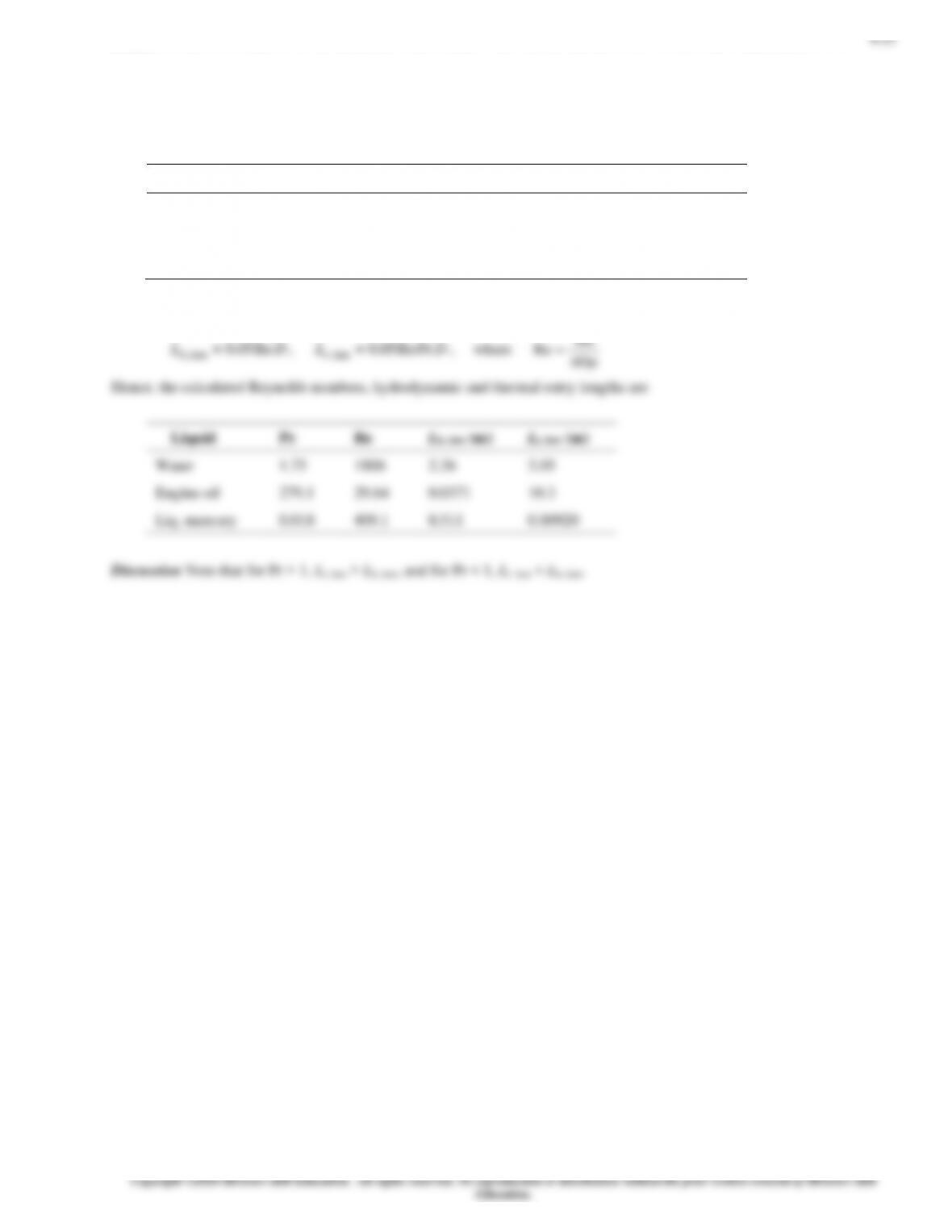
8-48E For a given mass flow rate, the average velocity, hydrodynamic and thermal entry lengths for water, engine oil, and
liquid mercury flowing through a standard 2-in Schedule 40 pipe are to be determined.
Assumptions 1 Steady operating conditions exist. 2 Properties are constant. 3 Flow is isothermal.
Properties The properties of water, engine oil, and liquid mercury at 100°F are listed in the following table:
Liquid
(lbm/ft3)
(lbm/ft∙s)
Pr
Water (Table A-9E)
62.00
4.578 10−4
4.54
Engine oil (Table A-13E)
54.77
163.0 10−3
3275
Liq. mercury (Table A-14E)
842.9
9.919 10−4
0.02363
Analysis The average velocity, hydrodynamic and thermal entry lengths can be calculated using the following equations:
m
m
4
8-29
8-51 Liquid water entering at 40°C and flowing at 0.0036 kg/s is heated in a circular copper tube with a constant surface
heat flux. The surface temperature of the tube is to be determined whether it exceeds the maximum use temperature of 204°C
set by the ASME Code for Process Piping. The axial location where the surface temperature reaches 204°C is to be
determined.
Assumptions 1 The flow is steady and incompressible. 2 Uniform surface heat flux. 3 Inner surface of the tube is smooth.
Properties The properties of water at 100°C are (Table A–9) cp = 4217 J/kg∙K, k = 0.679 W/m∙K, μ = 0.282 × 10⁻³ kg/m∙s,
and Pr = 1.75
Analysis The Reynolds number for the flow in circular tube is
The tube surface temperature at the exit (x = L) is
𝑇𝑠,𝐿 = 𝑇𝑒+𝑞̇𝑠
ℎ=158.57℃ +7639.4 W/m2
118.42 W/m2⋅ K =𝟐𝟐𝟑.𝟎𝟖℃ > 204℃
where the constant surface heat flux is
8-30
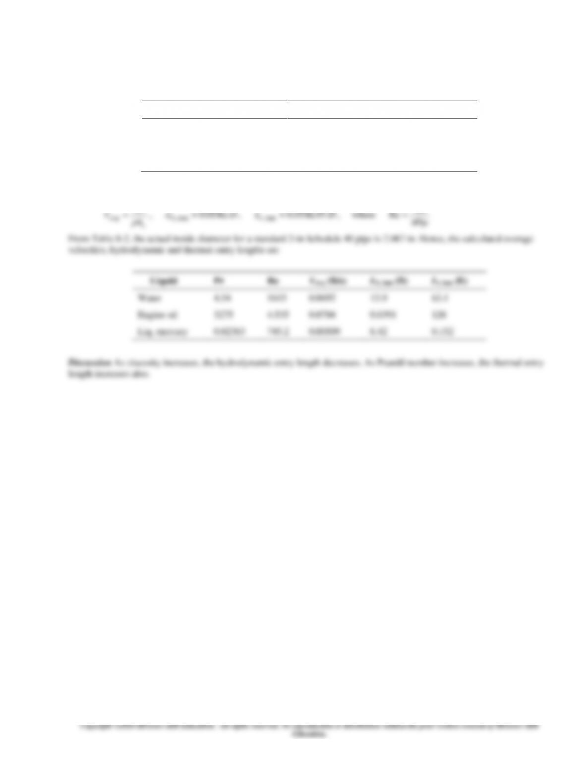
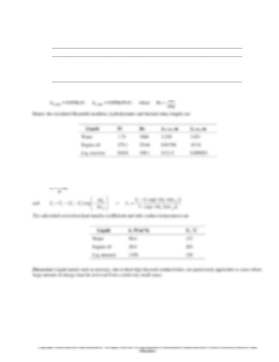
8-52 The tube surface temperatures necessary to heat water, engine oil, and liquid mercury to the desired outlet temperature
of 150°C are to be determined.
Assumptions 1 Steady operating conditions exist. 2 Properties are constant. 3 Constant tube surface temperature.
Properties The properties of water, engine oil, and liquid mercury at Tb = (Ti + Te)/2 = 100°C are listed in the following table:
Liquid
cp, J/kg∙K
k, W/m∙K
, kg/m∙s
Pr
Water (Table A-9)
4217
0.679
0.282 10−3
1.75
Engine oil (Table A-13)
2220
0.1367
17.18 10−3
279.1
Liq. mercury (Table A-14)
137.1
9.46706
1.245 10−3
0.0180
Analysis The hydrodynamic and thermal entry lengths can be calculated using the following equations:
m
4
8-33
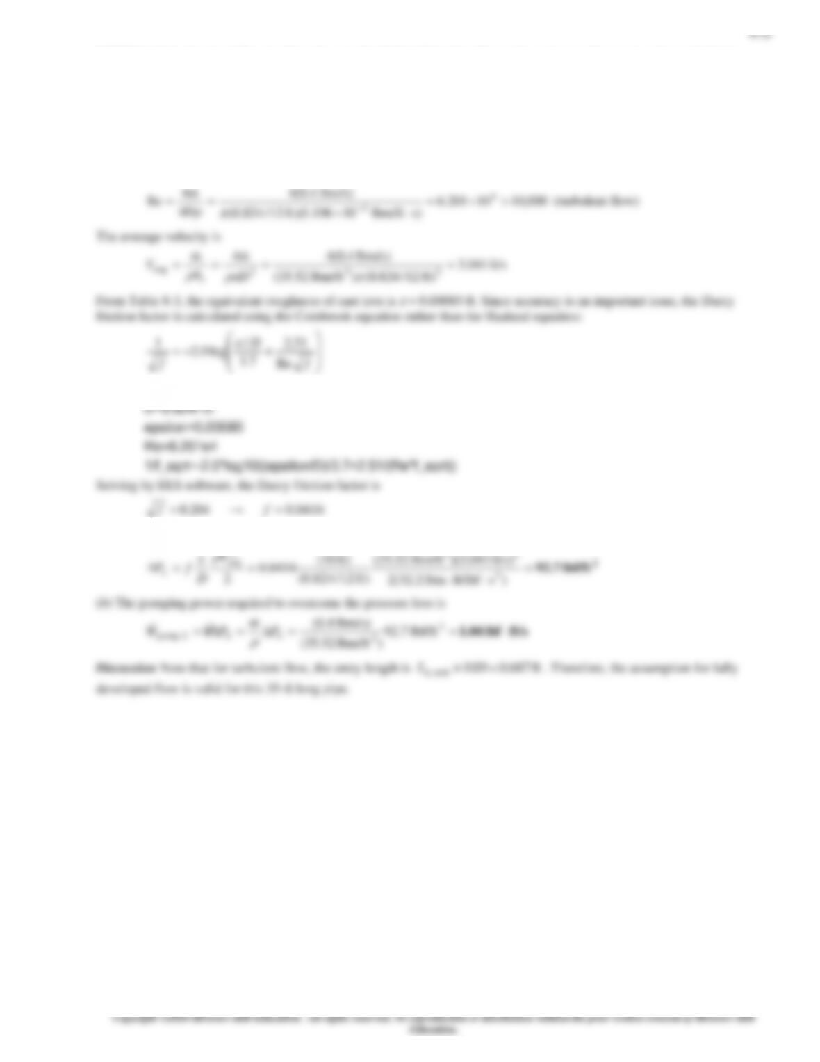
8-55 Water is flowing through a standard 1-in Schedule 40 cast iron pipe, (a) the pressure loss and (b) the pumping power
required to overcome the pressure loss are to be determined.
Assumptions 1 Steady operating conditions exist. 2 Properties are constant. 3 Flow is isothermal. 4 Flow is fully developed.
Properties The properties of water at 15°C are
= 999.1 kg/m3 and
= 1.138 10−3 kg/m∙s (from Table A-9).
Analysis From Table 8-2, a standard 1-in Schedule 40 pipe has an actual inside diameter of
m 02664.0in. 049.1 ==D
The Reynolds number for the flow is
)kg/s 5.0(44
m
(a) The pressure loss in the pipe is
)m/s 8978.0)(kg/m 1.999(
)m 02664.0(
)m 200(
2
23
2
avg
V
D
L
(b) The pumping power required to overcome the pressure loss is
)kg/m 1.999(
)kg/s 5.0(
3
m
Discussion Note that for turbulent flow, the entry length is
m 2664.010
turb, = DLh
. Therefore, the assumption for fully
8-34
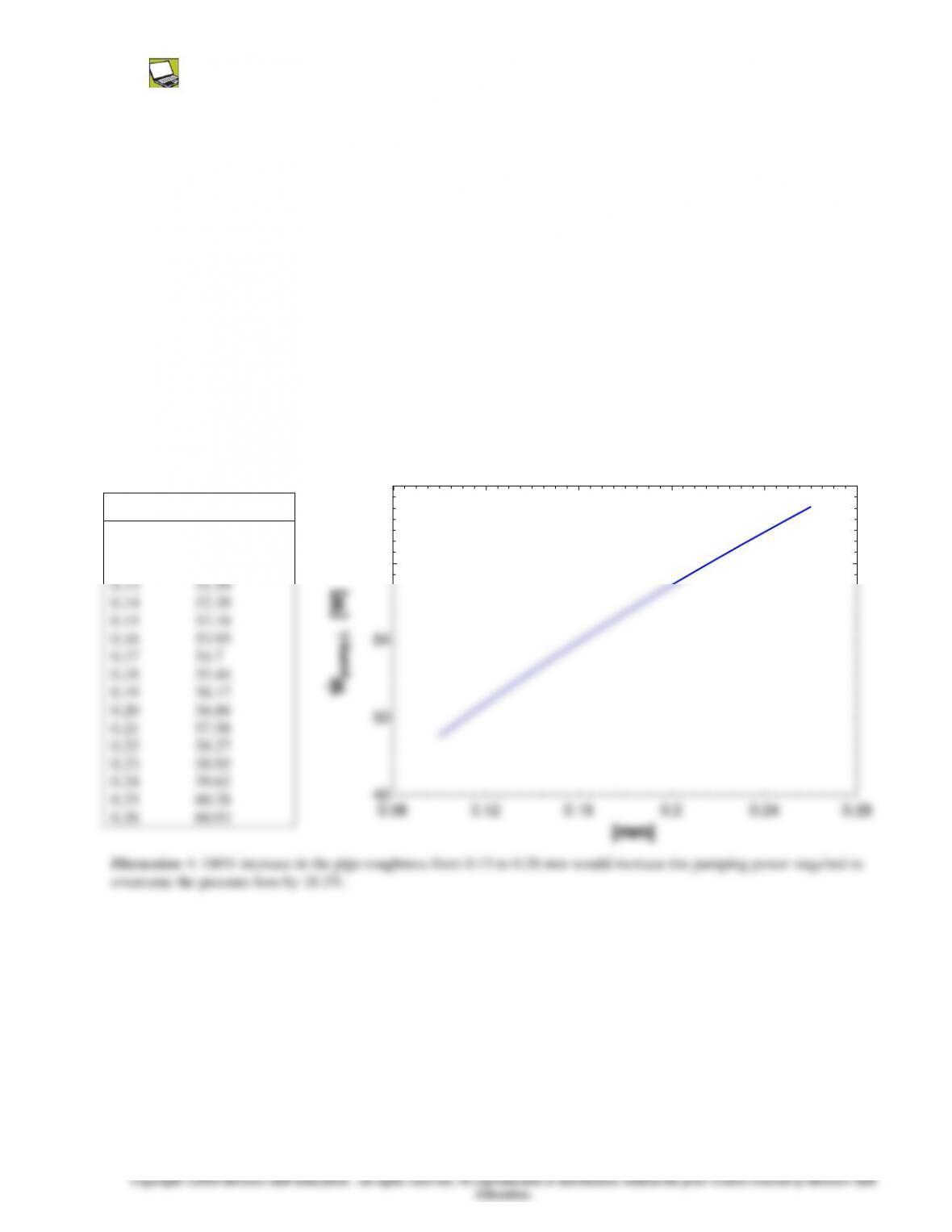
8-56 Prob. 8-55 is reconsidered. The effect of the pipe roughness on the pumping power is to be evaluated.
Analysis The problem is solved using EES, and the solution is given below.
"GIVEN"
T_b=15 [C]
D=1.049*0.0254 [m]
L=200 [m]
m_dot=0.5 [kg/s]
"PROPERTIES"
rho=Density(water, T=T_b, P=101.3)
mu=Viscosity(water, T=T_b, P=101.3)
"ANALYSIS"
A_c=pi#*D^2/4 "Cross-section area"
Re=4*m_dot/(pi#*D*mu)
V_avg=m_dot/(rho*A_c)
1/f^0.5=-2.0*log10((epsilon*1e-3/D)/3.7+2.51/(Re*f^0.5))
DELTAP_L=f*L/D*rho*V_avg^2/2
W_dot_pump_L=m_dot*DELTAP_L/rho
ε [mm] Ẇpump, L [W]
0.1 49.07
0.11 49.93
0.12 50.77
0.13 51.59
0.14 52.39
0.15 53.18
0.16 53.95
0.17 54.7
0.18 55.44
0.19 56.17
0.20 56.88
0.21 57.58
0.22 58.27
0.23 58.95
0.24 59.62
0.25 60.28
0.26 60.93
Discussion A 100% increase in the pipe roughness from 0.13 to 0.26 mm would increase the pumping power required to
overcome the pressure loss by 18.1%.
0.08 0.12 0.16 0.2 0.24 0.28
46
50
54
58
62
e [mm]
Wpump,L [W]
8-36
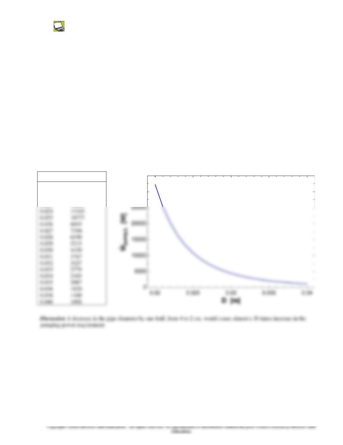
8-58 Prob. 8-57 is reconsidered. The effect of the pipe diameter on the pumping power is to be evaluated.
Analysis The problem is solved using EES, and the solution is given below.
"GIVEN"
T_b=15 [C]
L=25 [m]
Vol_dot=0.007 [m^3/s]
epsilon=0.002 [mm]
"PROPERTIES"
rho=Density(water, T=T_b, P=101.3)
mu=Viscosity(water, T=T_b, P=101.3)
"ANALYSIS"
A_c=pi#*D^2/4 "Cross-section area"
V_avg=Vol_dot/A_c
Re=rho*V_avg*D/mu
1/f^0.5=-2.0*log10((epsilon*1e-3/D)/3.7+2.51/(Re*f^0.5))
DELTAP_L=f*L/D*rho*V_avg^2/2
W_dot_pump_L=Vol_dot*DELTAP_L
D [m] Ẇpump, L [W]
0.020 32292
0.021 25385
0.022 20188
0.023 16225
0.024 13165
0.025 10777
0.026 8893
0.027 7394
0.028 6190
0.029 5215
0.030 4420
0.031 3767
0.032 3227
0.033 2779
0.034 2403
0.035 2087
0.036 1820
0.038 1400
0.040 1092
Discussion A decrease in the pipe diameter by one-half, from 4 to 2 cm, would cause almost a 30 times increase in the
pumping power requirement.
0.02 0.025 0.03 0.035 0.04
0
5000
10000
15000
20000
25000
30000
35000
D [m]
Wpump,L [W]
8-37
8-59 A fluid with mean inlet temperature Ti is flowing through a tube, of diameter D and length L, at a mass flow rate
m
; an
expression for the mean temperature of the fluid Tm(x) is to be determined from the given surface heat flux,
)/sin()( Lxbaxqs
+=
.
Assumptions 1 Steady operating conditions exist. 2 Properties are constant. 3 Heat conduction in the x-direction is negligible.
4 Work done by viscous forces is negligible.
Analysis Applying the energy balance to a differential control volume in a tube gives
p
8-39
8-61 Water enters a 25-mm diameter and 23-m long circular tube, (a) an expression for the mean temperature Tm(x), (b) the
outlet mean temperature, and (c) the value of a uniform heat flux on the tube surface that would result in the same outlet
mean temperature calculated in part (b) are to be determined.
Assumptions 1 Steady operating conditions exist. 2 Properties are constant. 3 Heat conduction in the x-direction is negligible.
4 Work done by viscous forces is negligible.
Properties The constant pressure specific heat of water at 35°C is cp = 4178 J/kg∙K (Table A-9).
Analysis (a) Applying the energy balance to a differential control volume in a tube gives
p
2
cm
p
(b) The outlet mean temperature is at x = L, hence
3
2)m 23(
)m 025.0() W/m400(
Da
8-40
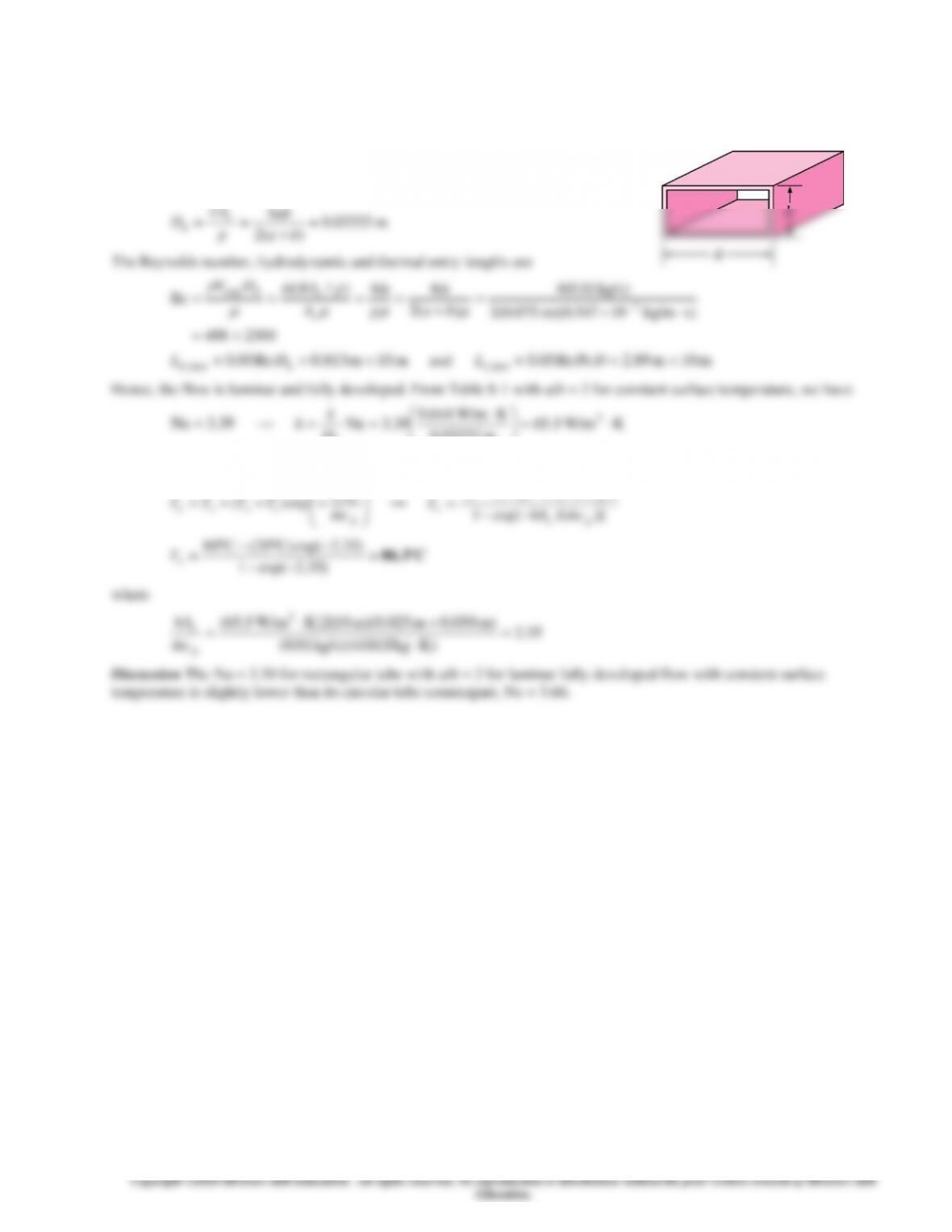
8-62 The rectangular tube surface temperature necessary to heat water to the desired outlet temperature of 80°C is to be
determined.
Assumptions 1 Steady operating conditions exist. 2 Properties are constant. 3 Constant tube surface temperature.
Properties The properties of water at Tb = (Ti + Te)/2 = 50°C:
cp = 4181 J/kg∙K, k = 0.644 W/m∙K,
= 0.547 10−3 kg/m∙s,
and Pr = 3.55 (Table A-15).
Analysis The hydraulic diameter is
4
4=
ab
A


