3-121
3-154 A thin-walled cylindrical container, filled with chemicals undergoing exothermic reaction, is buried in fresh snow. The
reaction provides a uniform heat generation. The snow surface is maintained at a specified temperature. The container surface
temperature is to be determined.
Assumptions 1 Steady operating conditions exist. 2 Heat transfer is two-dimensional (no change in the axial direction). 3
Thermal conductivity of the ground is constant. 4 Isothermal container surface.
Properties The thermal conductivity of fresh snow is k = 0.60 W/mK (Table A-8).
Analysis The shape factor for this configuration is given in Table 3-7 (Case 1) to be
)m 5.1(2
2===
L
)m 793.3)(KW/m60.0(4
4
2
2
1
kS
kS
Discussion The surface temperature of the container is below the freezing point of water, therefore the snow around the
container will not melt.
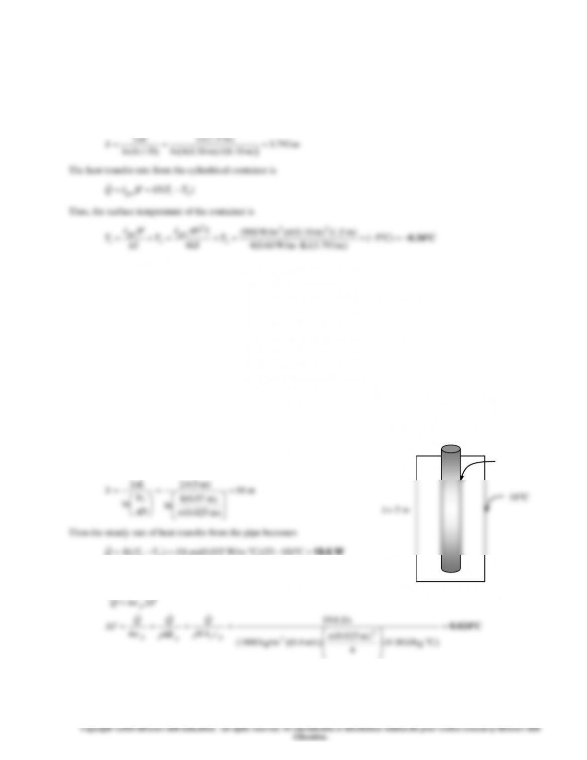
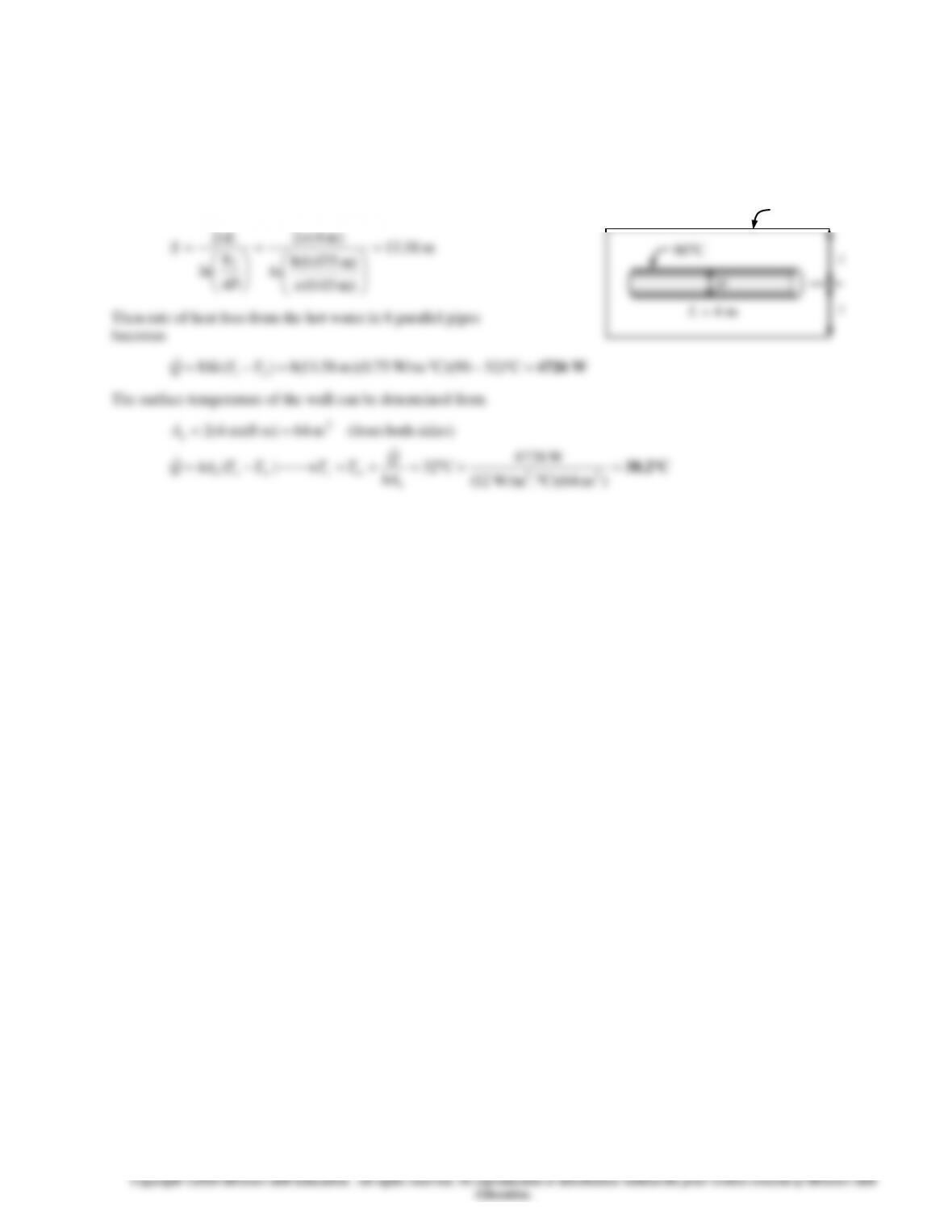
3-155 Hot water flows through a 5-m long section of a thin walled hot water pipe that passes through the center of a 14–cm
thick wall filled with fiberglass insulation. The rate of heat transfer from the pipe to the air in the rooms and the temperature
drop of the hot water as it flows through the pipe are to be determined.
Assumptions 1 Steady operating conditions exist. 2 Heat transfer is two-dimensional (no change in the axial direction). 3
Thermal conductivity of the fiberglass insulation is constant. 4 The pipe is at the same temperature as the hot water.
Properties The thermal conductivity of fiberglass insulation is given to be
k = 0.035 W/m°C.
Analysis (a) The shape factor for this configuration is given in Table 3-7 to
be
)m 5(2
2=
L
(b) Using the water properties at the room temperature, the temperature drop
of the hot water as it flows through this 5-m section of the wall becomes
=
)CJ/kg. 4180(
4
)m 025.0(
)m/s 4.0)(kg/m 1000(
J/s 6.19
2
3
pc
p
p
p
cVA
Q
c
Q
cm
Q
TcmQ
V
53C
D =2.5 cm
3-122
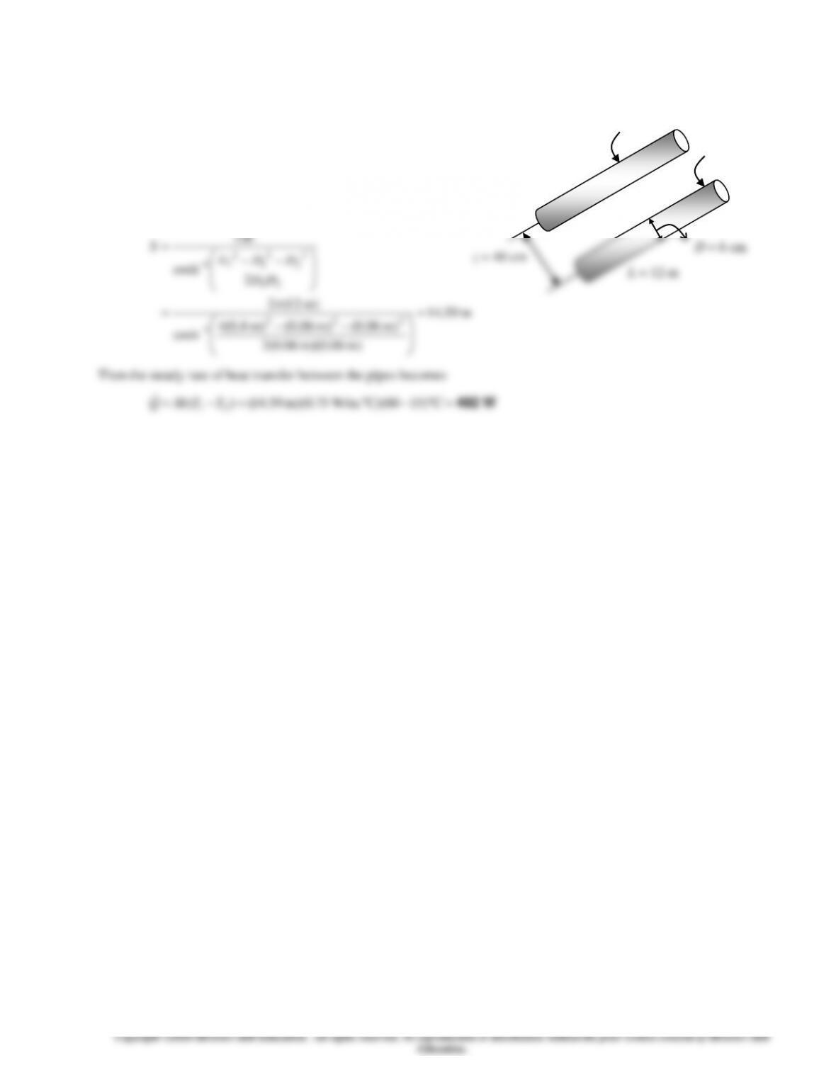
3-156 Hot and cold water pipes run parallel to each other in a thick concrete layer. The rate of heat transfer between the pipes
is to be determined.
Assumptions 1 Steady operating conditions exist. 2 Heat transfer is two-
dimensional (no change in the axial direction). 3 Thermal conductivity of the
concrete is constant.
Properties The thermal conductivity of concrete is given to be k = 0.75
W/m°C.
Analysis The shape factor for this configuration is given in
Table 3-7 to be
2
4
cosh
2
21
2
2
2
1
2
1
−−
=
−
DD
DDz
L
S
T2 = 15C
D = 6 cm
T1 = 60C
L = 12 m
z = 40 cm
3-123
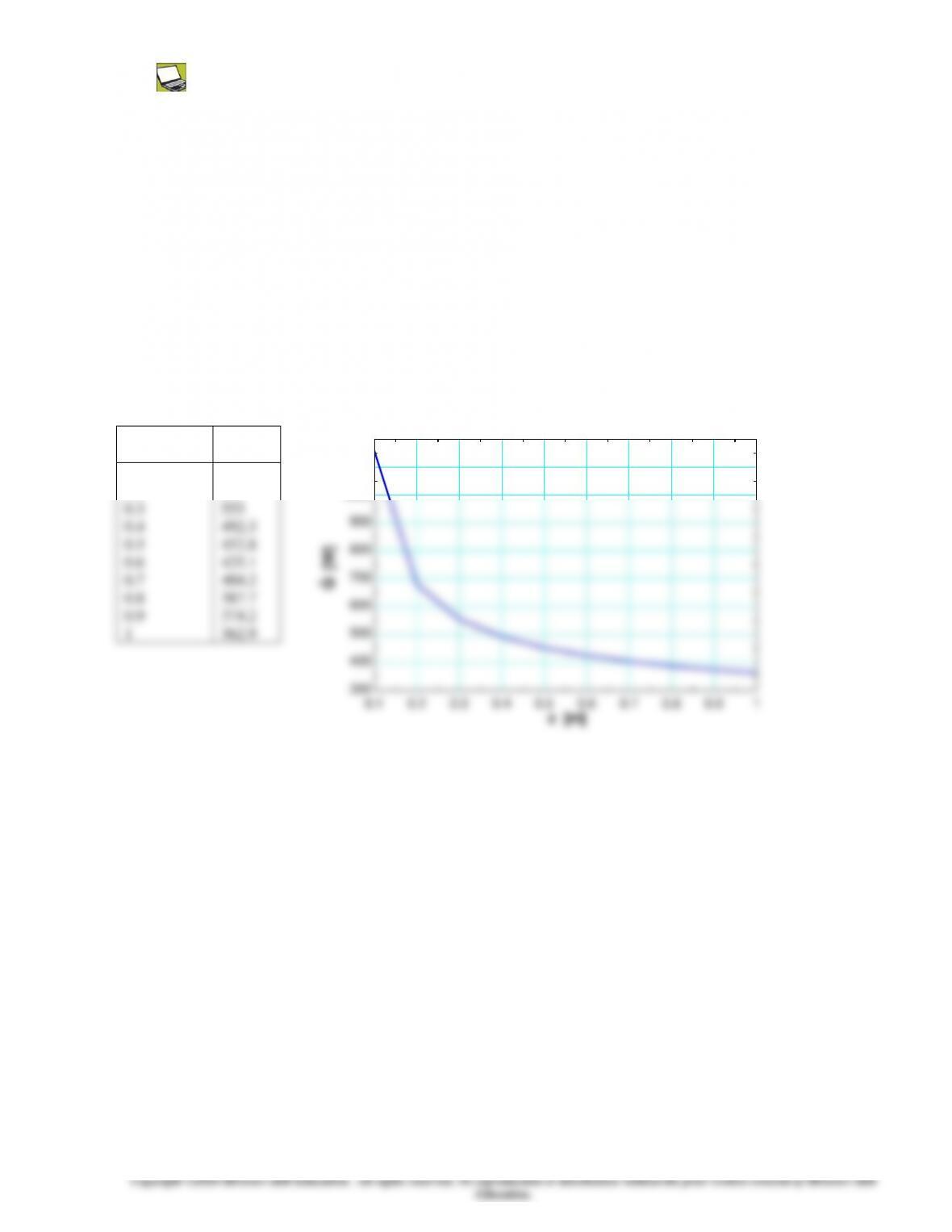
3-157 Prob. 3-156 is reconsidered. The rate of heat transfer between the pipes as a function of the distance between the
centerlines of the pipes is to be plotted.
Analysis The problem is solved using EES, and the solution is given below.
“GIVEN”
L=12 [m]
D_1=0.06 [m]
D_2=D_1
z=0.40 [m]
T_1=60 [C]
T_2=15 [C]
k=0.75 [W/m-C]
“ANALYSIS”
S=(2*pi*L)/(arccosh((4*z^2-D_1^2-D_2^2)/(2*D_1*D_2)))
Q_dot=S*k*(T_1-T_2)
z
[m]
Q
[W]
0.1
0.2
0.3
0.4
0.5
0.6
0.7
0.8
0.9
1
1158
679
555
492.3
452.8
425.1
404.2
387.7
374.2
362.9
0.1 0.2 0.3 0.4 0.5 0.6 0.7 0.8 0.9 1
300
400
500
600
700
800
900
1000
1100
1200
z [m]
Q [W]
3-124
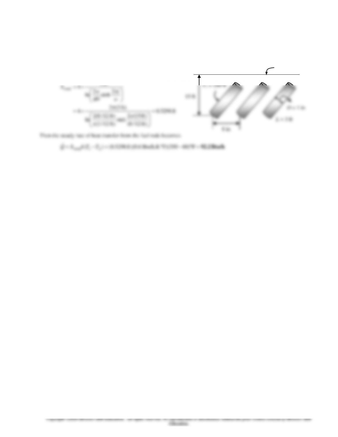
3-158E A row of used uranium fuel rods are buried in the ground parallel to each other. The rate of heat transfer from the
fuel rods to the atmosphere through the soil is to be determined.
Assumptions 1 Steady operating conditions exist. 2 Heat transfer is two-dimensional (no change in the axial direction). 3
Thermal conductivity of the soil is constant.
Properties The thermal conductivity of the soil is given to be k = 0.6 Btu/hft°F.
Analysis The shape factor for this configuration
is given in Table 3-7 to be
ft 5298.0
)ft 12/8(
)ft 15(2
sinh
)ft 12/1(
)ft 12/8(2
ln
)ft 3(2
4
2
sinh
2
ln
2
4
total
=
=
=
w
z
D
w
L
S
Then the steady rate of heat transfer from the fuel rods becomes
Btu/h 92.2=−=−= F)60350)(FBtu/h.ft. 6.0)(ft 5298.0()( 21total TTkSQ
T2 = 60F
8 in
T1 = 350F
15 ft
D = 1 in
L = 3 ft
3-125
3-126
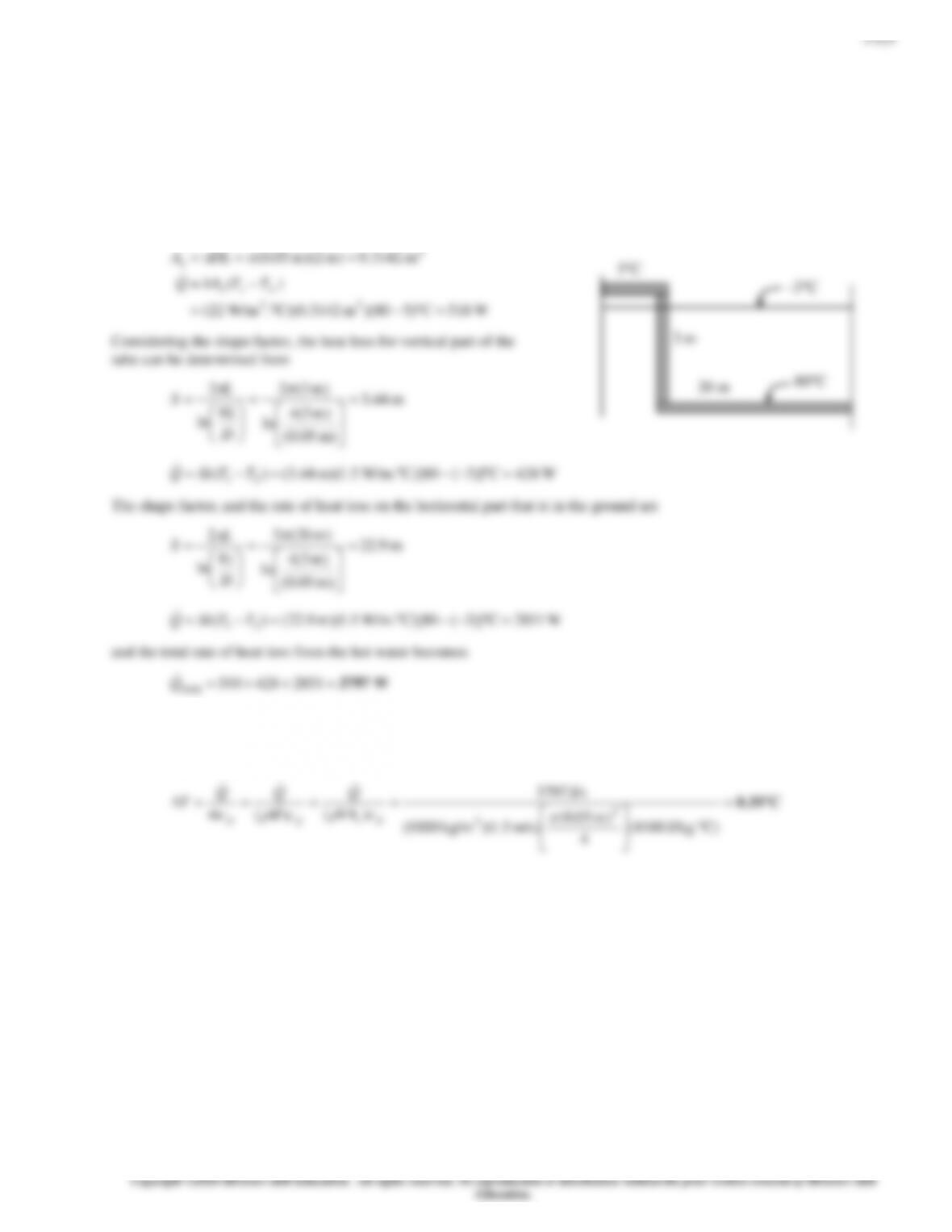
3-160 Hot water passes through a row of 8 parallel pipes placed vertically in the middle of a concrete wall whose surfaces are
exposed to a medium at 32C with a heat transfer coefficient of 8 W/m2.C. The rate of heat loss from the hot water, and the
surface temperature of the wall are to be determined.
Assumptions 1 Steady operating conditions exist. 2 Heat transfer is two-dimensional (no change in the axial direction). 3
Thermal conductivity of concrete is constant.
Properties The thermal conductivity of concrete is given to be k = 0.75 W/m°C.
Analysis The shape factor for this configuration is given in Table 3-7 to be
90C
)m 4(2
2=
L
C38.2=
+=+=⎯→⎯−=
)m 64)(C. W/m12(
C32)(
22
s
sss
hA
TTTThAQ
32C
3-127
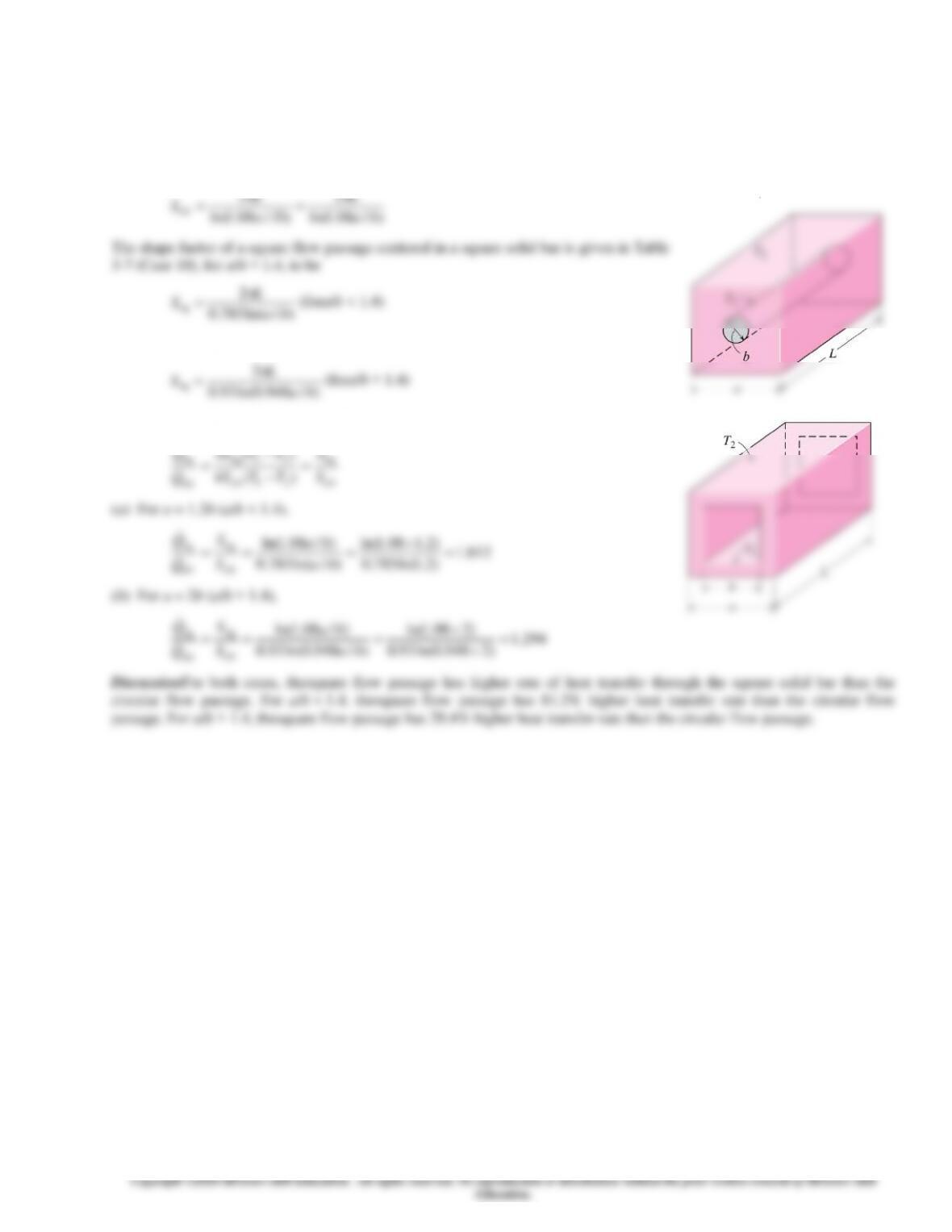
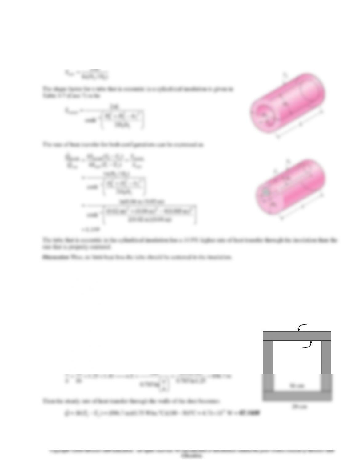
3-161 Two flow passages of the same length but of different cross-sectional shapes. Each flow passage is centered in a square
solid bar of the same length. The configuration that has the higher rate of heat transfer through the square solid bar is to be
determined.
Assumptions 1 Steady operating conditions exist. 2 Heat transfer is two-dimensional (no change in the axial direction). 3
Thermal conductivitiesare constant. 4 Isothermal surfaces.
Analysis The shape factor of a circular flow passage centered in a square solid bar is given in Table 3-7 (Case 6) to be
2
2
L
L
)/ln(785.0
sq ba
and
)/948.0ln(93.0
2
sq ba
L
The rate of heat transfer for both configurations can be expressed as
sq
21sq
sq
)(
S
TTkS
Q=
−
3-128
3-129
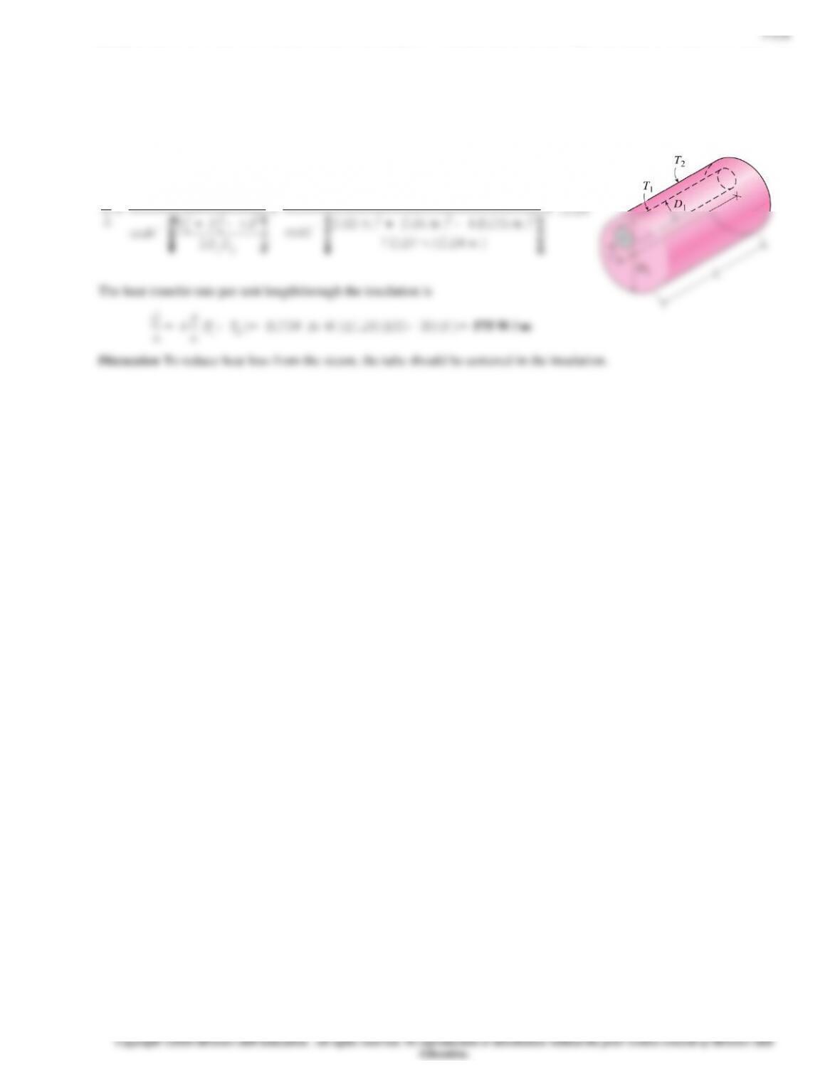
3-163 Two circular tubes, one is properly centered in a cylindrical insulation material but the other is not. The configuration
that has the higher rate of heat transfer through the insulation is to be determined.
Assumptions 1 Steady operating conditions exist. 2 Heat transfer is two-dimensional (no change in the axial direction). 3
Thermal conductivityis constant. 4 Isothermal surfaces.
Analysis The shape factor for a tube centered in a cylindrical insulation is given in Table 3-7 (Case 9) to be
2
L
3-164 The inner and outer surfaces of a long thick-walled concrete duct are maintained at specified temperatures. The rate of
heat transfer through the walls of the duct is to be determined.
Assumptions 1 Steady operating conditions exist. 2 Heat transfer is two-dimensional (no
change in the axial direction). 3 Thermal conductivity of the concrete is constant.
Properties The thermal conductivity of concrete is given to be k = 0.75
W/m°C.
Analysis The shape factor for this configuration is given in Table 3-7 to be
)m 25(2
2
20 ==
L
a
100C
30C
3-130
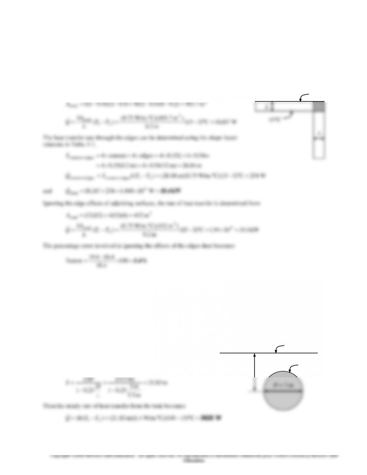
3-165 The walls and the roof of the house are made of 20-cm thick concrete, and the inner and outer surfaces of the house are
maintained at specified temperatures. The rate of heat loss from the house through its walls and the roof is to be determined,
and the error involved in ignoring the edge and corner effects is to be assessed.
Assumptions 1 Steady operating conditions exist. 2 Heat transfer at the edges and corners is two-or three-dimensional. 3
Thermal conductivity of the concrete is constant. 4 The edge effects of adjoining surfaces on heat transfer are to be
considered.
Properties The thermal conductivity of the concrete is given to be k = 0.75 W/m°C.
Analysis The rate of heat transfer excluding the edges and corners is first determined to
be
2
4.18
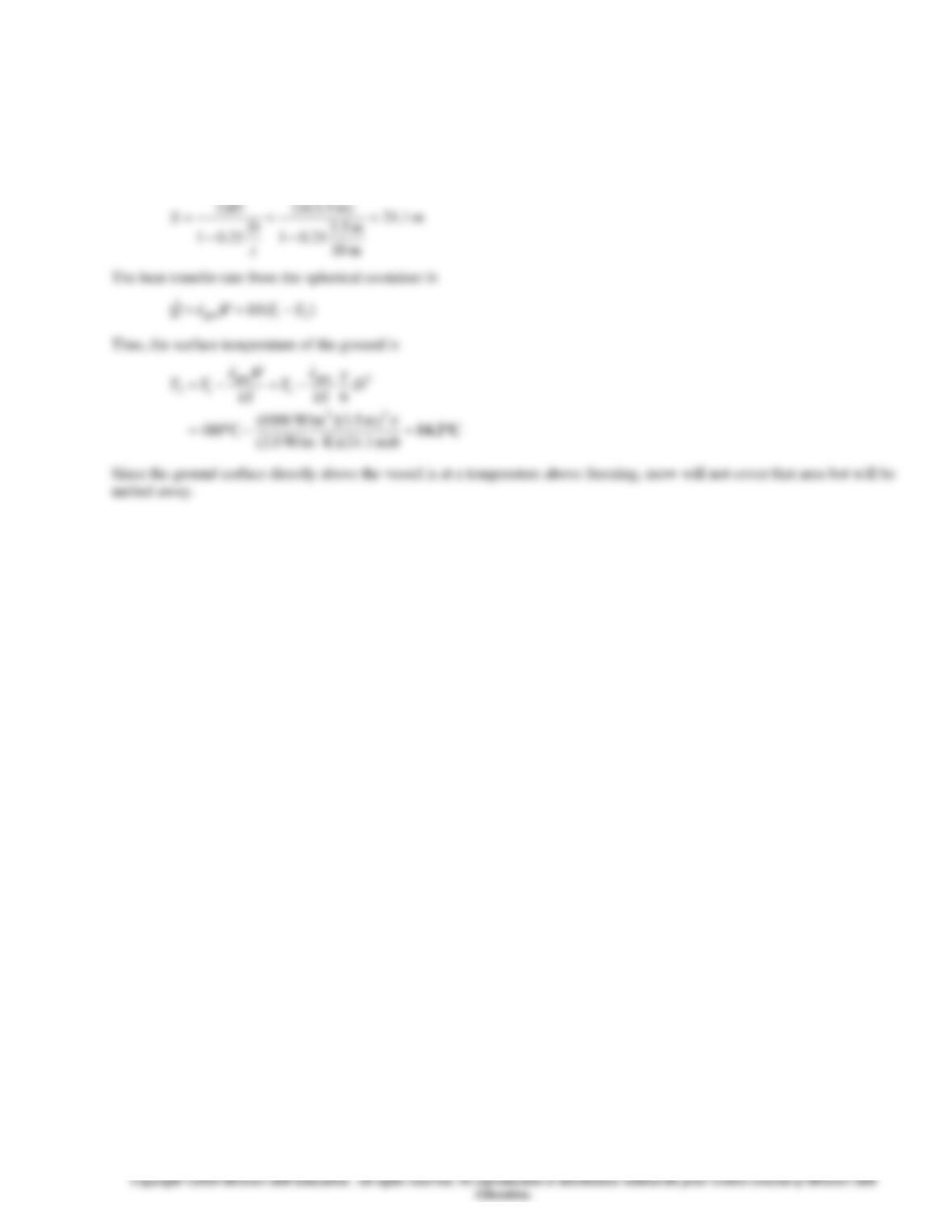
3-166 A spherical tank containing some radioactive material is buried in the ground. The tank and the ground surface are
maintained at specified temperatures. The rate of heat transfer from the tank is to be determined.
Assumptions 1 Steady operating conditions exist. 2 Heat transfer is two-dimensional (no change in the axial direction). 3
Thermal conductivity of the ground is constant.
Properties The thermal conductivity of the ground is given to be
k = 1.4 W/m°C.
Analysis The shape factor for this configuration is given in Table
3-7 to be
)m 3(2
2=
D
3C
T2 =15C
T1 = 140C
z = 5.5 m
3-131
3-167 Radioactive material is stored in a spherical vessel that is buried underground. The ground surface temperature directly
above the vessel is to be determined.
Assumptions 1 Steady operating conditions exist. 2 Heat transfer is two-dimensional (no change in the axial direction). 3
Thermal conductivity of the ground is constant.4 Isothermal surfaces.
Properties The thermal conductivity of the ground is given to be k = 2.0 W/mK.
Analysis The shape factor for this configuration is given in Table 3-7 (Case 15) to be
)m 5.3(2
2=
D
3-132
Special Topic: Heat Transfer through the Walls and Roofs
3-169C The effective emissivity for a plane-parallel air space is the “equivalent” emissivity of one surface for use in the
relation
)( 4
1
4
2effectiverad TTAQ s−=
that results in the same rate of radiation heat transfer between the two surfaces across
3-170C The unit thermal resistances (R-value) of both 40-mm and 90-mm vertical air spaces are given to be the same, which
3-171C Radiant barriers are highly reflective materials that minimize the radiation heat transfer between surfaces. Highly
3-172C The roof of a house whose attic space is ventilated effectively so that the air temperature in the attic is the same as
3-133
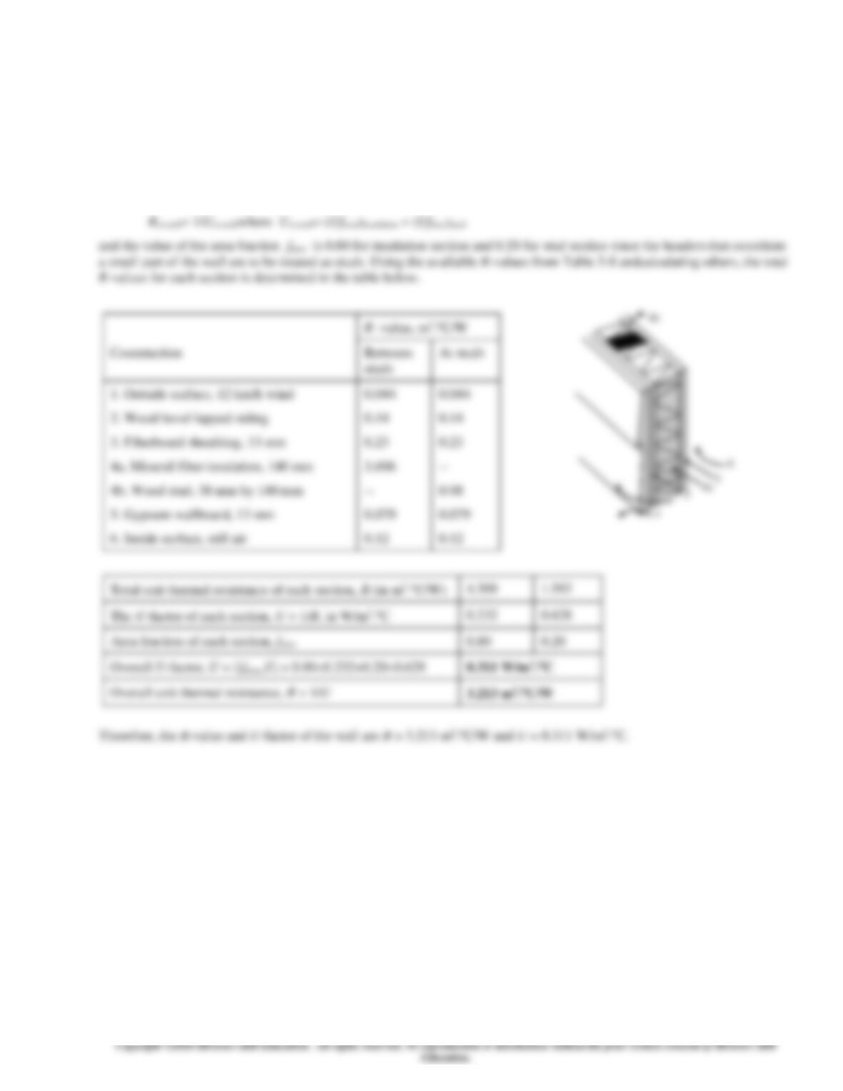
3-173 The R-value and the U-factor of a wood frame wall are to be determined.
Assumptions 1 Steady operating conditions exist. 2 Heat transfer through the wall is one-dimensional. 3 Thermal properties
of the wall and the heat transfer coefficients are constant.
Properties The R-values of different materials are given in Table 3–8.
AnalysisThe schematic of the wall as well as the different elements used in its construction are shown below. Heat transfer
through the insulation and through the studs will meet different resistances, and thus we need to analyze the thermal
resistance for each path separately. Once the unit thermal resistances and the U-factorsfor the insulation and stud sections are
available, the overall average thermal resistance for the entire wall can be determined from
3-134
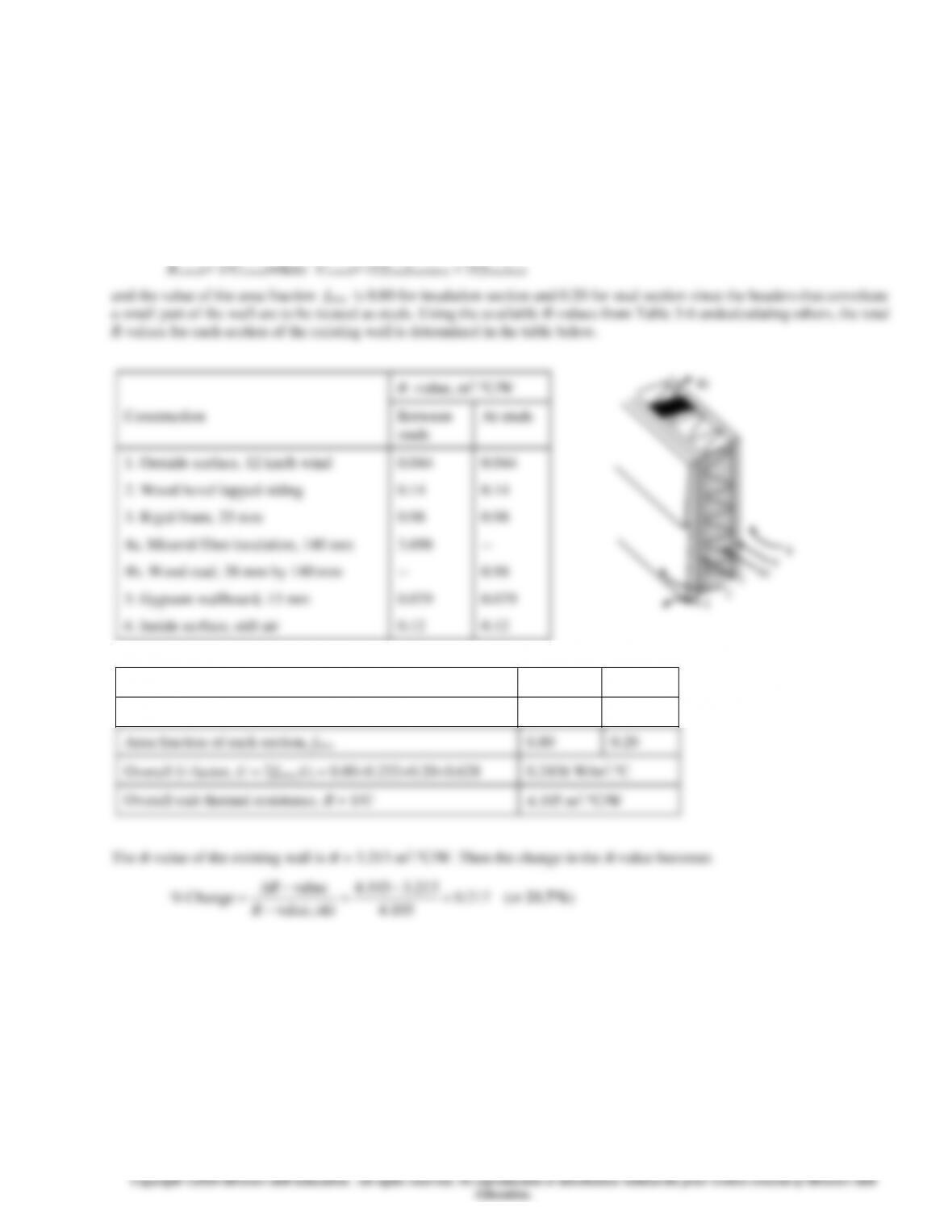
3-174 The change in the R-value of a wood frame wall due to replacing fiberwood sheathing in the wall by rigid foam
sheathing is to be determined.
Assumptions 1 Steady operating conditions exist. 2 Heat transfer through the wall is one-dimensional. 3 Thermal properties
of the wall and the heat transfer coefficients are constant.
Properties The R–values of different materials are given in Table 3–8.
AnalysisThe schematic of the wall as well as the different elements used in its construction are shown below. Heat transfer
through the insulation and through the studs will meet different resistances, and thus we need to analyze the thermal
resistance for each path separately. Once the unit thermal resistances and the U-factorsfor the insulation and stud sections are
available, the overall average thermal resistance for the entire wall can be determined from
R –value, m2.C/W
Construction
Between
studs
At studs
1. Outside surface, 12 km/h wind
0.044
0.044
2. Wood bevel lapped siding
0.14
0.14
3. Rigid foam, 25 mm
0.98
0.98
4a. Mineral fiber insulation, 140 mm
4b. Wood stud, 38 mm by 140 mm
3.696
—
—
0.98
5. Gypsum wallboard, 13 mm
0.079
0.079
6. Inside surface, still air
0.12
0.12
Total unit thermal resistance of each section, R (in m2.C/W)
5.059
2.343
The U-factor of each section, U = 1/R, in W/m2.C
0.198
0.426
Area fraction of each section, farea
0.80
0.20
Overall U-factor, U = farea,iUi = 0.800.232+0.200.628
0.2436 W/m2.C
Overall unit thermal resistance, R = 1/U
4.105 m2.C/W
1
2
3
4a
5
6
4b
3-135
3-136
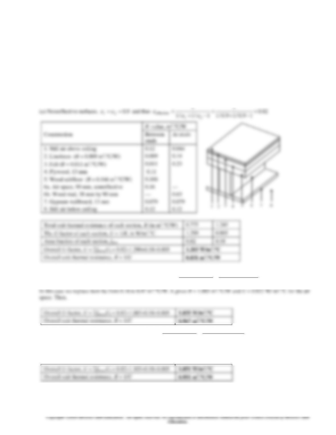
3-176 The winter R-value and the U-factor of a flat ceiling with an air space are to be determined for the cases of air space
with reflective and nonreflective surfaces.
Assumptions 1 Steady operating conditions exist. 2 Heat transfer through the ceiling is one-dimensional. 3 Thermal
properties of the ceiling and the heat transfer coefficients are constant.
Properties The R-values are given in Table 3-8 for different materials, and in Table 3-11 for air layers.
AnalysisThe schematic of the ceiling as well as the different elements used in its construction are shown below. Heat transfer
through the air space and through the studs will meet different resistances, and thus we need to analyze the thermal resistance
for each path separately. Once the unit thermal resistances and the U–factorsfor the air space and stud sections are available,
the overall average thermal resistance for the entire wall can be determined from
Roverall= 1/Uoverallwhere Uoverall= (Ufarea)air space + (Ufarea)stud
and the value of the area fraction farea is 0.82 for air space and 0.18 for stud section since the headers which constitute a
small part of the wall are to be treated as studs.
1
1
3-137
3-138
3-178 The winter R-value and the U-factor of a masonry cavity wall with a reflective surface are to be determined.
Assumptions 1 Steady operating conditions exist. 2 Heat transfer through the wall is one-dimensional. 3 Thermal properties
of the wall and the heat transfer coefficients are constant.
Properties The R-values of different materials are given in Table 3-8. The R-values of air spaces are given in Table 3-11.
AnalysisThe schematic of the wall as well as the different elements used in its construction are shown below. Heat transfer
through the air space and through the studs will meet different resistances, and thus we need to analyze the thermal resistance
for each path separately. Once the unit thermal resistances and the U–factorsfor the air space and stud sections are available,
the overall average thermal resistance for the entire wall can be determined from
R –value, m2.C/W
Construction
Between
furring
At
furring
1. Outside surface, 24 km/h
0.030
0.030
2. Face brick, 100 mm
0.12
0.12
3. Air space, 90-mm, reflective with =
0.05
0.45
0.45
4. Concrete block, lightweight, 100–mm
0.27
0.27
5a. Air space, 20 mm, reflective with
=0.05
5b. Vertical ferring, 20 mm thick
0.49
—
—
0.94
6. Gypsum wallboard, 13
0.079
0.079
7. Inside surface, still air
0.12
0.12
Total unit thermal resistance of each section, R
1.559
2.009
The U-factor of each section, U = 1/R, in W/m2.C
0.641
0.498
Area fraction of each section, farea
0.84
0.16
Overall U-factor, U = farea,iUi = 0.840.641+0.160.498
0.618 W/m2.C
Overall unit thermal resistance, R = 1/U
1.62 m2.C/W
Therefore, the overall unit thermal resistance of the wall is R = 1.62 m2.C/W and the overall U-factor is U = 0.618 W/m2.C.
These values account for the effects of the vertical ferring.
DiscussionThe change in the U-value as a result of adding reflective surfaces is
368.0
978.0
618.0978.0
ivenonreflect value,
value
Change =
−
=
−
−
=U
U
Therefore, the rate of heat transfer through the wall will decrease by 36.8% as a result of adding a reflective surface.
1
2
3
4
5a
6
3-139
3-140