3-101
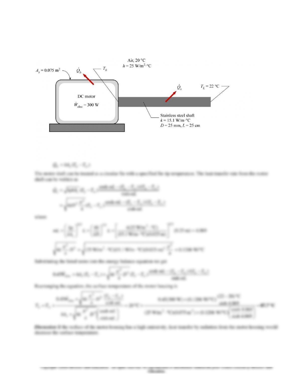
3-135 A DC motor draws electrical power and delivers mechanical power to rotate a stainless steel shaft. The surface
temperature of the motor housing is to be determined.
Assumptions1 Heat conduction is steady and one-dimensional. 2 Thermal properties are constant. 3 Heat transfer by radiation
is negligible. 4 The surface temperature of the motor housing is uniform. 5 The base temperature of the shaft is equal to the
surface temperature of the motor housing.
Properties The thermal conductivity of the stainless steel shaft is given as 15.1 W/m ∙ °C.
Analysis From energy balance, the following equation is expressed:
sh QQWW
++= mechelec
or
sh QQWW
++= elecelec 55.0
The heat transfer rate from the motor housing surface is
3-102
3-103
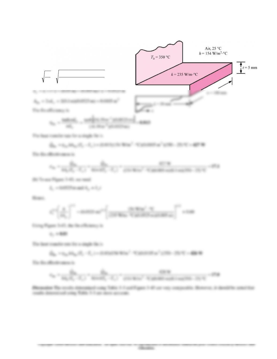
3-137 Using Table 3-3 and Figure 3-43, the efficiency, heat transfer rate, and effectiveness of a straight rectangular fin are to
be determined.
Assumptions1 Heat conduction is steady and one-dimensional. 2 Thermal properties are constant. 3 Heat transfer by radiation
is negligible.
Properties The thermal conductivity of
the fin is given as 235 W/m ∙ °C.
Analysis (a) From Table 3-3, for straight
rectangular fins, we have
1
2
m 19.16
)m 005.0)(C W/m235(
)C W/m154(22 –
kt
h
m=
==
m 0525.02/)m 005.0()m 05.0(2/ =+=+= tLLc
2
fin m 0105.0)m 0525.0)(m 1.0(22 === c
wLA
The fin efficiency is
0.813=== )m 0525.0)(m 19.16(
)m 0525.0)(m 19.16(tanh
tanh
1
1
fin –
–
c
c
mL
mL
The heat transfer rate for a single fin is
W427=−=−= C )25350)(m 0105.0)(C W/m154)(813.0()( 22
finfinfin TThAQb
The fin effectiveness is
17.1=
−
=
−
=
−
=
C )25350)(m 1.0)(m 005.0)(C W/m154(
W427
))(()( 2
finfin
fin TTtwh
Q
TThA
Q
bbb
(b) To use Figure 3-43, we need
m 0525.0=
c
L
and
tLA cp =
Hence,
60.0
)m 005.0)(m 0525.0)(C W/m235(
C W/m154
)m 0525.0(
2/1
2
2/3
2/1
2/3
=
p
ckA
h
L
Using Figure 3-43, the fin efficiency is
0.81
f
The heat transfer rate for a single fin is
W426=−=−= C )25350)(m 0105.0)(C W/m154)(81.0()( 22
finfinfin TThAQb
The fin effectiveness is
17.0=
−
=
−
=
−
=
C )25350)(m 1.0)(m 005.0)(C W/m154(
W426
))(()( 2
finfin
fin TTtwh
Q
TThA
Q
bbb
Discussion The results determined using Table 3-3 and Figure 3-43 are very comparable. However, it should be noted that
results determined using Table 3-3 are more accurate.
3-104
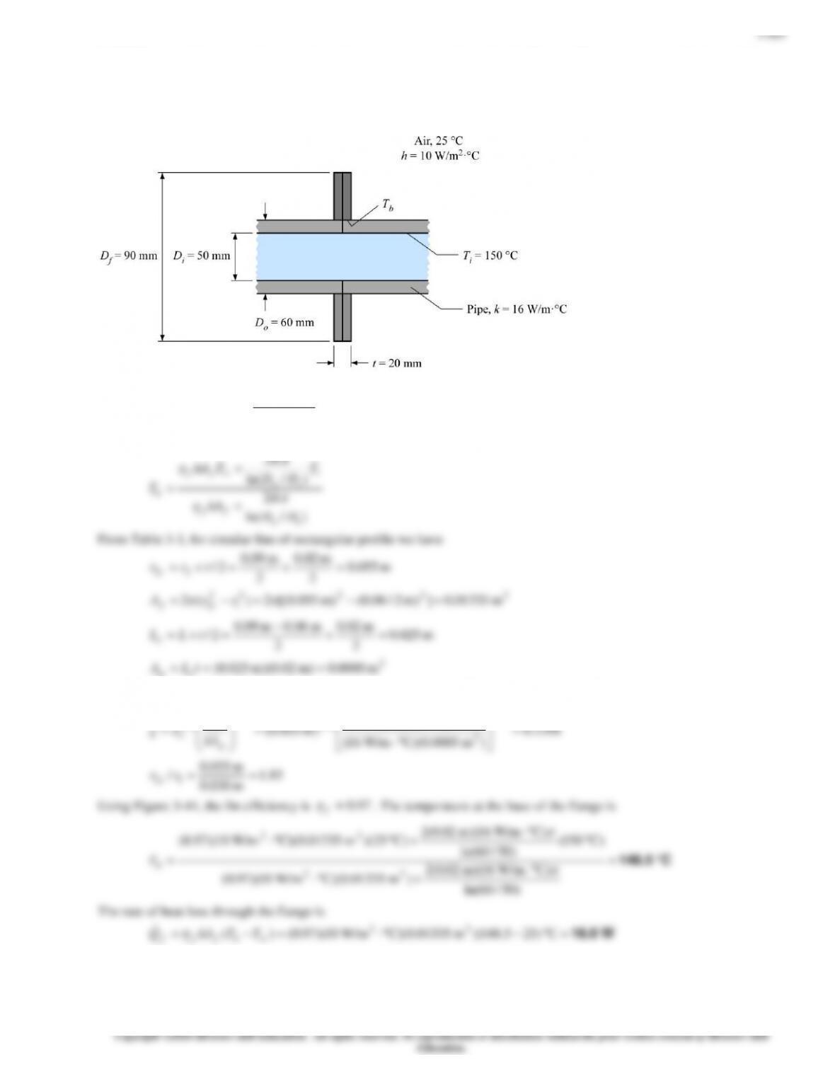
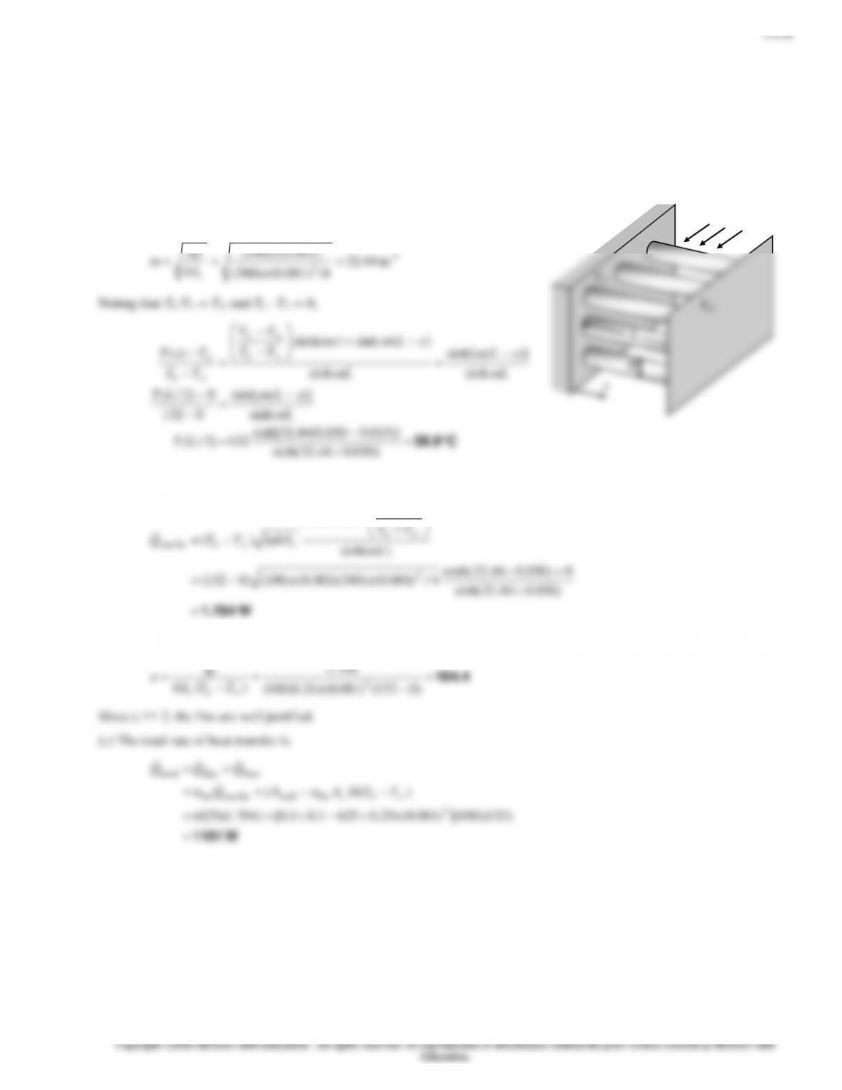
3-138 Two cast iron steam pipes are connected to each other through two 1-cm thick flanges exposed to cold ambient air.
The average outer surface temperature of the pipe, the fin efficiency, the rate of heat transfer from the flanges, and the
equivalent pipe length of the flange for heat transfer are to be determined.
Assumptions 1 Steady operating conditions exist. 2 The temperature along the flanges (fins) varies in one direction only
(normal to the pipe). 3 The heat transfer coefficient is constant and uniform over the entire fin surface. 4 The thermal
properties of the fins are constant. 5 The heat transfer coefficient accounts for the effect of radiation from the fins.
Properties The thermal conductivity of the cast iron is given to be k = 52 W/m°C.
Analysis (a) We treat the flanges as fins. The individual thermal resistances are
2
2
m 513.2m) 8(m) 1.0(
m 312.2m) 8(m) 092.0(
===
===
LDA
LDA
oo
ii
)6.4/5ln(
)/ln(
C/W 00240.0
)m 312.2(C). W/m180(
11
12
22
i
=
==
ii
rr
Ah
R
Ri
Rcond
Ro
T1
T2
T1 T2
3-105
3-106
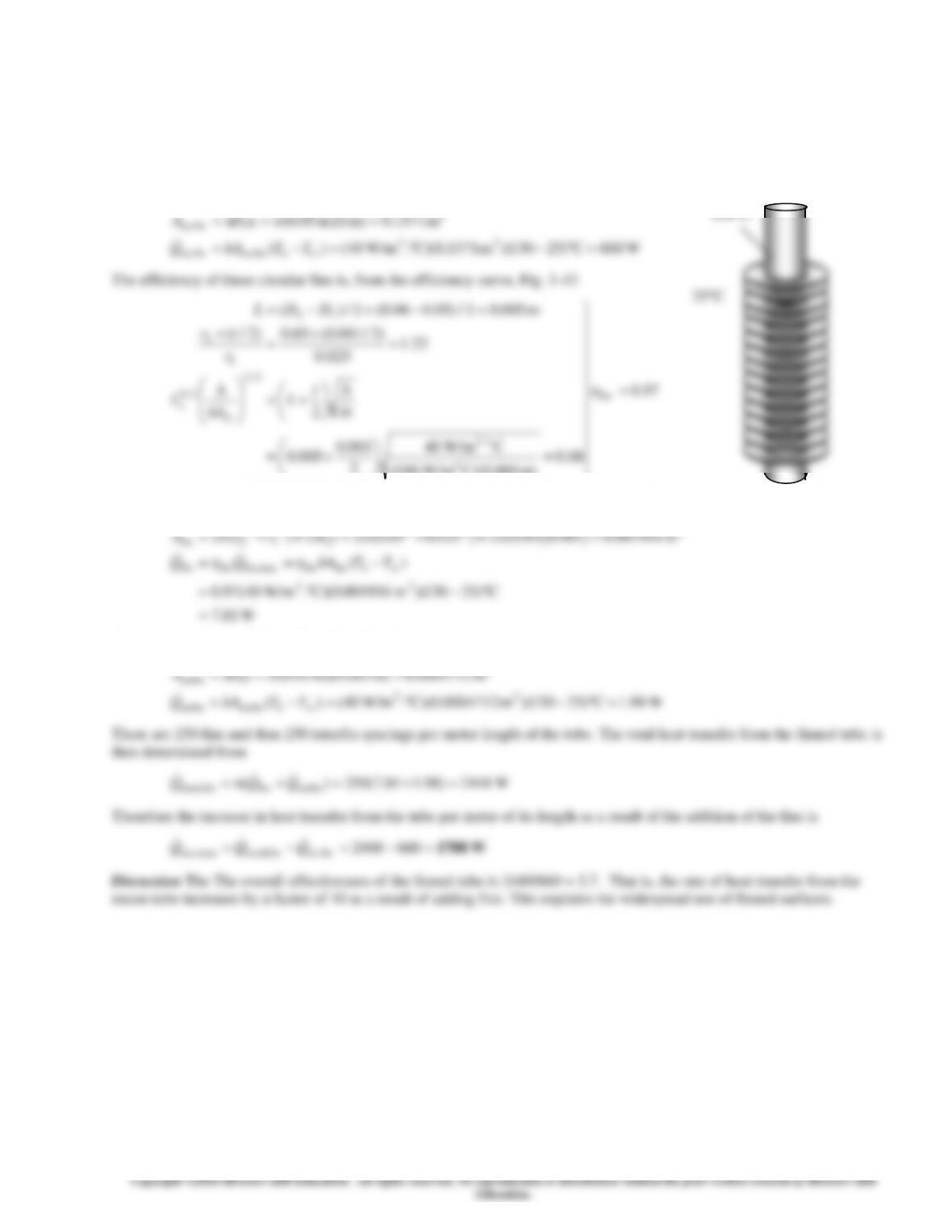
25C
3-140 Circular aluminum fins are to be attached to the tubes of a heating system. The increase in heat transfer from the tubes
per unit length as a result of adding fins is to be determined.
Assumptions 1 Steady operating conditions exist. 2 The heat transfer coefficient is constant and uniform over the entire fin
surfaces. 3 Thermal conductivity is constant. 4 Heat transfer by radiation is negligible.
Properties The thermal conductivity of the fins is given to be k = 186 W/m°C.
Analysis In case of no fins, heat transfer from the tube per meter of its length is
m 1571.0)m 1)(m 05.0(
2
1fin no
===
LDA
130C
3-107
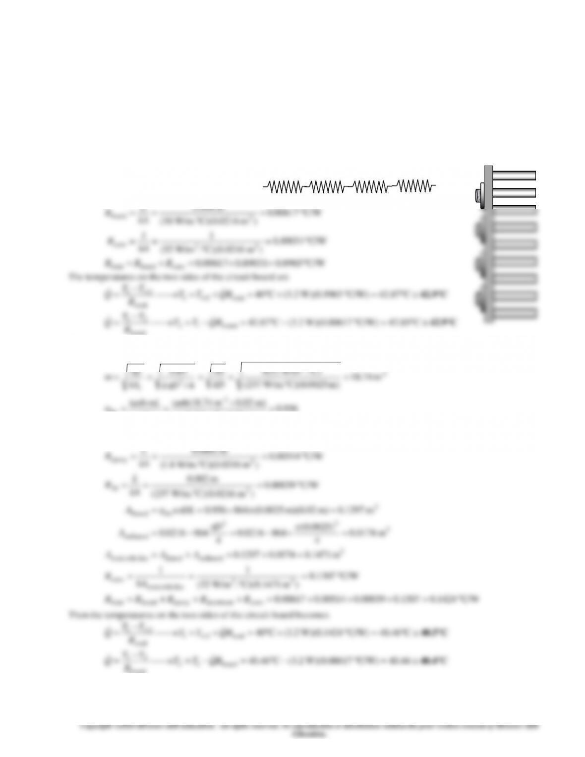
3-141 A circuit board houses 80 logic chips on one side, dissipating 0.04 W each through the back side of the board to the
surrounding medium. The temperatures on the two sides of the circuit board are to be determined for the cases of no fins and
864 aluminum pin fins on the back surface.
Assumptions 1 Steady operating conditions exist. 2 The temperature in the board and along the fins varies in one direction
only (normal to the board). 3 All the heat generated in the chips is conducted across the circuit board, and is dissipated from
the back side of the board. 4 Heat transfer from the fin tips is negligible. 5 The heat transfer coefficient is constant and
uniform over the entire fin surface. 6 The thermal properties of the fins are constant. 7 The heat transfer coefficient accounts
for the effect of radiation from the fins.
Properties The thermal conductivities are given to be k = 30 W/m°C for the circuit board, k = 237 W/m°C for the aluminum
plate and fins, and k = 1.8 W/m°C for the epoxy adhesive.
Analysis (a) The total rate of heat transfer dissipated by the chips is
W2.3 W)04.0(80 ==Q
The individual resistances are
2
m 0216.0m) 18.0(m) 12.0( ==A
C/W 00617.0
)m 0216.0(C) W/m.30(
m 004.0
2
board
=
==
kA
L
R
2 cm
Rboard
T1
RAluminum
Rconv
T2
Repoxy
T2
3-108
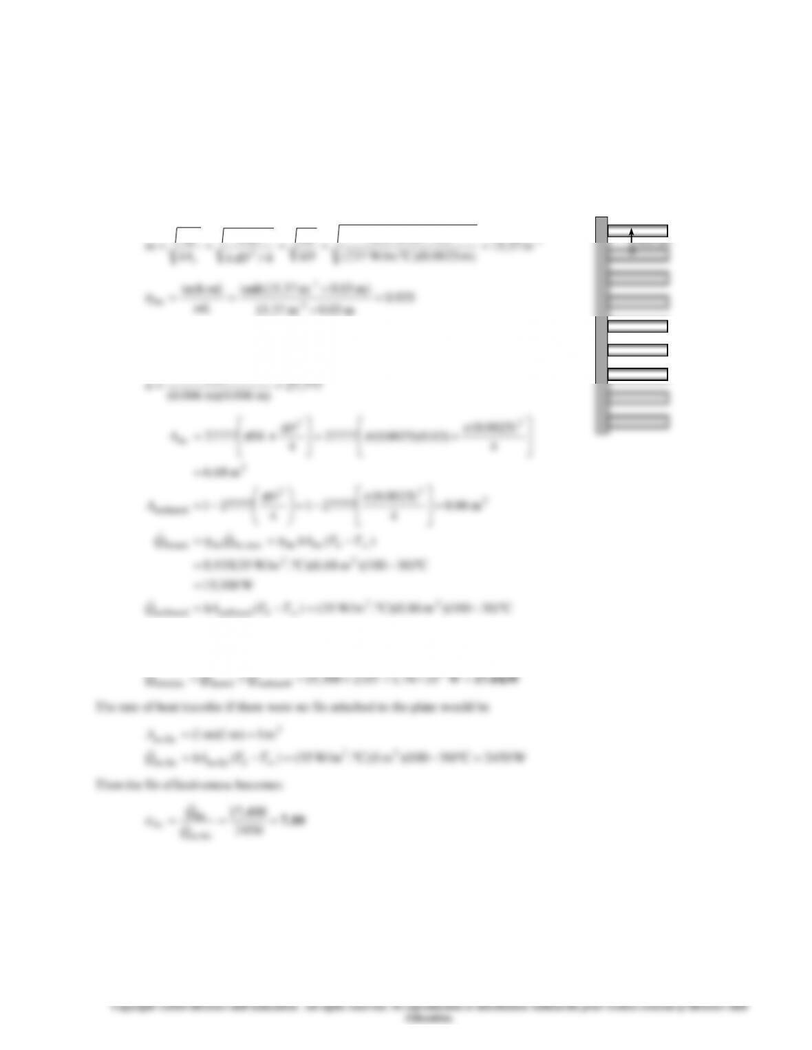
3-142 A hot plate is to be cooled by attaching aluminum pin fins on one side. The rate of heat transfer from the 1 m by 1 m
section of the plate and the effectiveness of the fins are to be determined.
Assumptions 1 Steady operating conditions exist. 2 The temperature along the fins varies in one direction only (normal to the
plate). 3 Heat transfer from the fin tips is negligible. 4 The heat transfer coefficient is constant and uniform over the entire fin
surface. 5 The thermal properties of the fins are constant. 6 The heat transfer coefficient accounts for the effect of radiation
from the fins.
Properties The thermal conductivity of the aluminum plate and fins is given to be k = 237 W/m°C.
Analysis Noting that the cross-sectional areas of the fins are constant, the efficiency
of the circular fins can be determined to be
1–
2
0.6 cm
)C. W/m35(4
4
h
Dh
hp
m 03.0m 37.15
1–
The number of fins, finned and unfinned surface areas, and heat transfer
rates from those areas are
777,27
m) 006.0(m) 006.0(
m 1 2
==n
W2107
C)30100)(m 86.0)(C. W/m35()(
W300,15
C)30100)(m 68.6)(C. W/m35(935.0
)(
m 86.0
4
)0025.0(
277771
4
277771
m 68.6
4
)0025.0(
)03.0)(0025.0(27777
4
27777
22
unfinnedunfinned
22
finfinmaxfin,finfinned
2
2
2
unfinned
2
2
2
fin
=
−=−=
=
−=
−==
=
−=
−=
=
+=
+=
TThAQ
TThAQQ
D
A
D
DLA
b
b
Then the total heat transfer from the finned plate becomes
fin no
fin Q
3 cm
D=0.25 cm
3-109
3-143 Prob. 3-142 is reconsidered. The effect of the center-to center distance of the fins on the rate of heat transfer
from the surface and the overall effectiveness of the fins is to be investigated.
Analysis The problem is solved using EES, and the solution is given below.
“GIVEN”
T_b=100 [C]
L=0.03 [m]
D=0.0025 [m]
k=237 [W/m-C]
S=0.6 [cm]
T_infinity=30 [C]
h=35 [W/m^2-C]
A_surface=1*1 [m^2]
“ANALYSIS”
p=pi*D
A_c=pi*D^2/4
a=sqrt((h*p)/(k*A_c))
eta_fin=tanh(a*L)/(a*L)
n=A_surface/(S^2*Convert(cm^2, m^2)) “number of fins”
A_fin=n*(pi*D*L+pi*D^2/4)
A_unfinned=A_surface-n*(pi*D^2/4)
Q_dot_finned=eta_fin*h*A_fin*(T_b-T_infinity)
Q_dot_unfinned=h*A_unfinned*(T_b-T_infinity)
Q_dot_total_fin=Q_dot_finned+Q_dot_unfinned
Q_dot_nofin=h*A_surface*(T_b-T_infinity)
epsilon_fin=Q_dot_total_fin/Q_dot_nofin
S
[cm]
Qtotal fin
[W]
fin
0.4
36123
14.74
0.5
24001
9.796
0.6
17416
7.108
0.7
13445
5.488
0.8
10868
4.436
0.9
9101
3.715
1
7838
3.199
1.1
6903
2.817
1.2
6191
2.527
1.3
5638
2.301
1.4
5199
2.122
1.5
4845
1.977
1.6
4555
1.859
1.7
4314
1.761
1.8
4113
1.679
1.9
3942
1.609
2
3797
1.55
0.25 0.6 0.95 1.3 1.65 2
0
5000
10000
15000
20000
25000
30000
35000
40000
0
2
4
6
8
10
12
14
16
18
20
S [cm]
Qtotal,fin [W]
fin
3-110
3-111
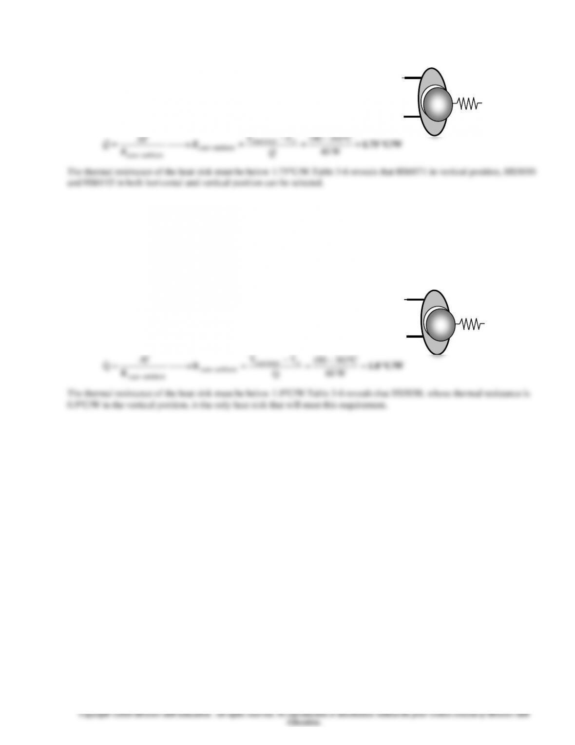
3-145 A commercially available heat sink is to be selected to keep the case temperature of a transistor below 90C in an
environment at 20C.
Assumptions 1 Steady operating conditions exist. 2 The transistor case is
isothermal at 90C. 3 The contact resistance between the transistor and the
heat sink is negligible.
Analysis The thermal resistance between the transistor attached to the sink
and the ambient air is determined to be
−
−
C)2090(
transistor
TT
T
3-146 A commercially available heat sink is to be selected to keep the case temperature of a transistor below 90C in an
environment at 30C.
Assumptions 1 Steady operating conditions exist. 2 The transistor case is isothermal
at 90
C
. 3 The contact resistance between the transistor and the heat sink is
negligible.
Analysis The thermal resistance between the transistor attached to the sink and the
ambient air is determined to be
C/W 1.0 =
−
=
−
=⎯→⎯=
−
− W06
C)3090(
Q
TT
R
R
T
Qtransistor
ambientcase
ambientcase
The thermal resistance of the heat sink must be below 1.0C/W.Table 3-6 reveals that HS5030, whose thermal resistance is
0.9C/W in the vertical position, is the only heat sink that will meet this requirement.
T
R
Ts
T
R
Ts
3-112
Bioheat Transfer Equation
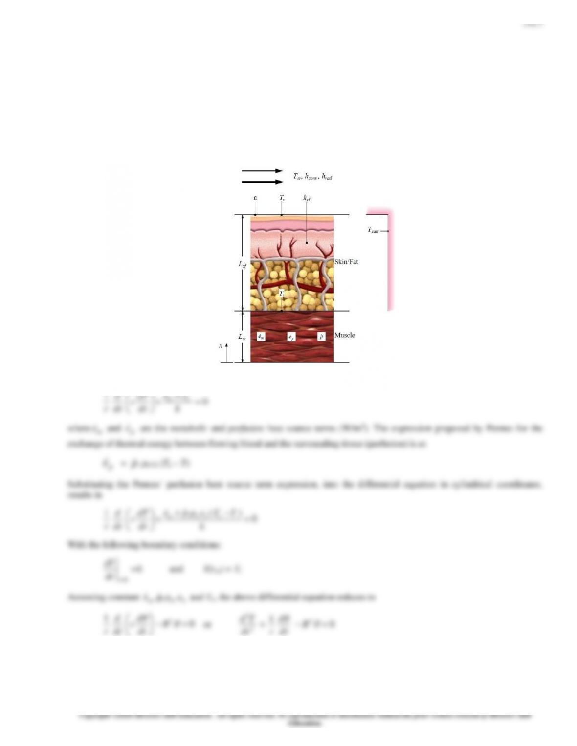
3-147 The different human body types with three different thicknesses of skin/fat layes are subjected to the varying ambient
temperature. The rate of metabolic heat generation is to be determined so as to maintain the skin temperarue constant at 34oC.
Assumptions1 Muscle and skin/fat layer considered as a 1-D plain wall. 2 Steady state conditions. 3 Blood properties,
thermal conductivities, arterial temperature, core body temperature, and perfusion rate are all constant. 4 The surrounding
temperature is the same as that of the ambient temperature. 5 Solar radiation is negligible.
Propertie: Constant thermophysical properties for skin and blood. Ambient temperature is varied between -20 and 20oC. Lsf
= 0.075, 0.005 and 0.003 m for three different body types.
Analysis Solve the bioheat transfer differential equation along with the appropriate boundary conditions to develop an
expression for the interface temperature (Ti) between the muscle and the outer skin/fat layer. The bioheat transfer differential
equation is given by Eq. 3-88.
2
2
d
m
cBL
sinh
Using the Fourier’s law of heat conduction, the rate of heat transfer that leaves the muscle at x = Lm and enters the skin/fat
layer is
m
mci
cm
Lx
m
Lx
mtempspecified BL
BL
ABk
dx
d
Ak
dx
dT
AkQ
mm sinh
1cosh)/(
.
−
−=−=−=
==
The rate at which heat is transferred through the skin/fat layer and into the environment is obtained by using the thermal
resistance network concept. The total rate of heat transfer through the skin/fat layer and into the environment (the rate of heat
loss from the body) is,
( )
radconv
radconv
s
sf
si
total
i
bRR
RR
TT
R
TT
R
TT
Q
+
−=
−
=
−
=
where the total resistance is
radconv
radconv
sfradconvsftotal RR
RR
RRRR +
+=+= −
and the individual resistances are
Ak
L
R
sf
sf
sf =
K/W 2778.0
8.1)/(2
11
22 =
==
mKmW
Ah
R
conv
conv
K/W 0941.0
8.1)/(9.5
11
22 =
==
mKmW
Ah
R
rad
rad
From the above heat balance, for the known values of skin temperature and the environment temperature, we find interface
temperature as,
sfbsi RQTT
+=
Equating the rate of heat transfer that leaves the muscle at x = Lm and enters the skin/fat layer with the rate at which heat is
transferred through the skin/fat layer and into the environment yields
total
i
m
mci
cm R
TT
BL
BL
ABk
−
=
−
−sinh
1cosh)/(
3-113
The rearrangement of above equation by replacing
i and
c with appropriate equations results in the equation to determine
the metabolic heat generation rate,
( ) ( )
1)cosh(
)cosh(
)sinh(
−
−+
−
=
m
bb
mai
totm
mi
mBL
cp
BLTT
ABRk
BLTT
e
where,
1
m 06 −
==
m
bb
k
cp
B
,
( )
94.2sinh =
m
BL
,
( )
107.3cosh =
m
BL
,
K W/m5.0 =
m
k
and
2
m .81=A
.
The muscle and skin/fat interface temperature is a variable that will change with the change in the ambient temperature and
the thickness of skin/fat layer. For all other known values, the metabolic heat generation rate (
m
e
) is calculated as shown in
table below.
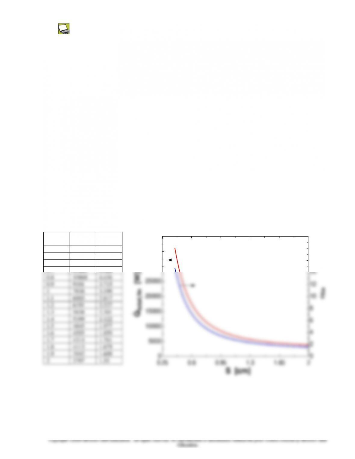
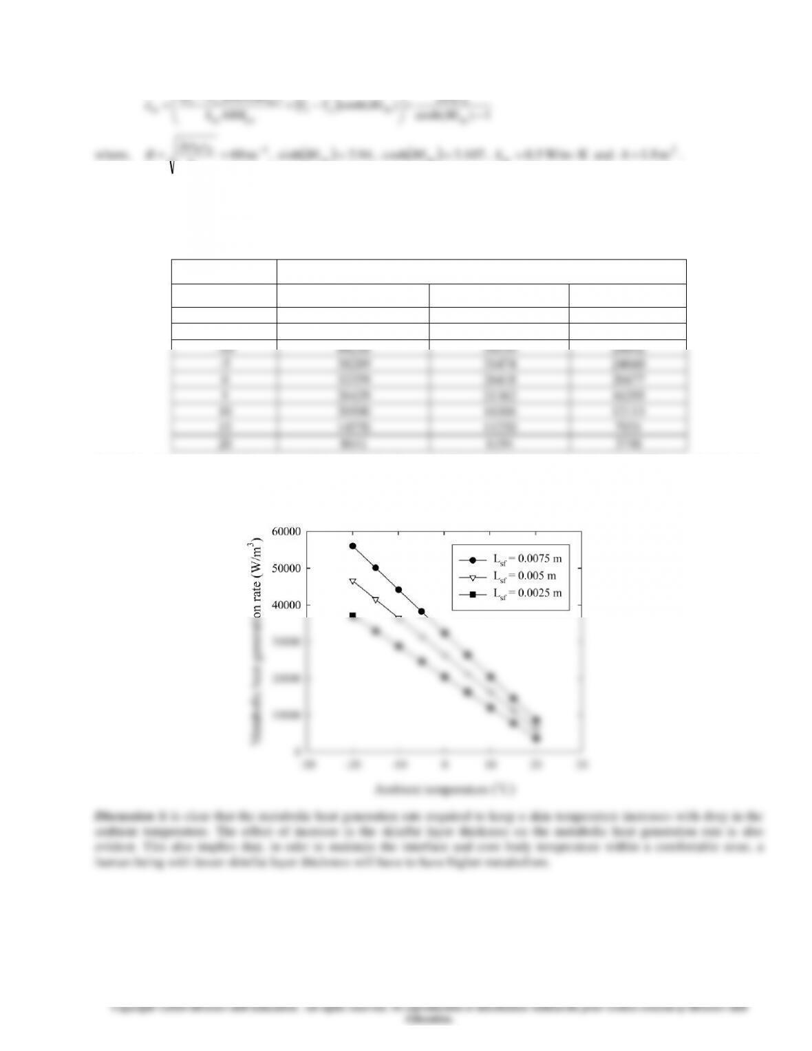
Metabolic heat generation rate as a function of ambient air temperature and skin/fat layer thickness
Metabolic heat generation rate
m
e
(W/m3)
T
(oC)
Lsf = 0.0075 m
Lsf = 0.005 m
Lsf = 0.0025 m
–20
56077
46642
37207
–15
50148
41586
33024
–10
44218
36530
28842
-5
38289
31474
24660
0
32359
26418
20477
5
26429
21362
16295
10
20500
16306
12113
15
14570
11250
7931
20
8641
6194
3748
Variation of the metabolic heat generation rate with change in the ambient temperature for three different skin/fat layer
thicknesses is shown graphically in the figure below.
3-114
3-148 The metabolic heat generation rate within human body is to be determined so as to maintain the skin temperature at
34oC.
Assumptions1 Muscle and skin/fat layer considered as a 1-D plain wall. 2 Steady state conditions. 3 Blood properties,
thermal conductivities, arterial temperature, core body temperature, and perfusion rate are all constant. 4 The surrounding
temperature is the same as that of the ambient temperature. 5 Solar radiation is negligible. 6. Same heat transfer everywhere
throughout the different parts of body.
Properties The convective heat transfer coefficients at T∞ = 15oC for air and water are 2 W/m2·K and 20 W/m2·K,
respectively. All other properties remain same as that of the example problem 3-14 in the text.
Analysis For this problem, the properties of human body parameters remain the same as that considered in example problem
3-14 in the text. However, the ambient and surrounding temperature is lowered to 15oC and has different convective heat
transfer coefficient when the human body is exposed to air and water.
The thermal resistance due to convection is
11
sf
m 1.8KW/m 0.3
Ak
sf
si =
We also know that, the muscle and skin/fat layer interface temperature Ti can be calculated using
mtotalmm
m
bb
m
actotalmm
iBLABRkBL
BL
cp
e
TABRkBLT
Tcoshsinh
coshsinh
+
+++
=
Rearrangement of this equation to find unknown metabolic heat generation rate yields
( ) ( )
1)cosh(
1
)cosh(
)cosh(
)sinh(
+
−+
−
=
m
mai
mtotm
mi
bbm BL
BLTT
BLABRk
BLTT
cpe
For the given conditions,
1
31
m60
K)(W/m 0.5
K)(J/kg 3600)(kg/m 1000)(s 0.0005 −
−
=
==
m
bb
k
cp
B
( )
94.2sinh =
m
BL
,
( )
107.3cosh =
m
BL
Putting these values in the equation for metabolic heat generation rate gives,
3
W/m1440=
m
e
(air environment)
Similarly using the convective heat transfer coefficient of 20 W/m2·K for water, we find,
3-115
( ) ( )
WC
RR
RR
TTQ
radconv
radconv
sb 7.887
09416.00277.0
09416.00277.0
1534 =
+
−=
+
−=
and
C3
m 1.8KW/m 0.3
m 0.003W 887.7
C
Ak
LQ
TT 2
sf
sfb
si =
+=+= 9.834
Using the equation for metabolic heat generation rate as above we get,
3
mW/m e 23937
=
(water environment).
Discussion The human body is adaptable to adjust with the surrounding thermal environment. For instance, if the
environmental conditions are cold, human body will adjust itself through the involuntarily motion of shivering. In this case,
for lower ambient temperature, metabolic heat generation achieved through shivering is about 6 times higher than that given
in example problem 3-14 in the text. In case of the water as surrounding fluid with about 10 times higher convective heat
transfer coefficient, the metabolic heat generation rate required to maintain the skin temperature at 34 oC is about 35 times
higher compared to that given in the example problem. This indicates that, for such a case only shivering motion may not be
sufficient to raise the body temperature and the human body may have to perform certain physical activity to increase the
metabolic heat generation rate.
3-116
3-117
3-118
d
The differential equation in terms of temperature excess
is a modified Bessel equation of order zero, and its general
solution is of the form
(r) = C1I0 (Br) + C2K0 (Br)
whereI0 and K0 are modified, zero-order Bessel functions of the first and second kinds, respectively.
d
)Br(I
cp
)Br(I
mbb
ai
m
0
0
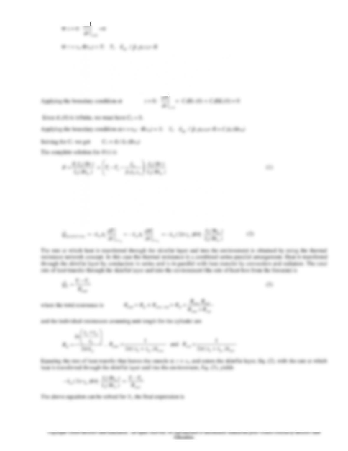
(b) In order to find Ti, use the above equation (note that Ti that appears in
i in Eq. (1) above is unknown). Follow the general
procedure used in the example problem on the application of the bioheat transfer equation. Use Eq. (1) to calculate the rate at
which heat leaves the muscle and enters the skin/fat layer at r = rm and equate it with the rate at which heat is transferred
through the skin/fat layer and into the environment.
Using the Fourier’s law of heat conduction, the rate of heat transfer that leaves the muscle at r = rm and enters the skin/fat
layer is
)Br(I
)Br(I
B)r(k
dr
d
Ak
dr
dT
AkQ
m
m
imm
rr
rm
rr
rm.tempspecified
mm 0
1
2
−=−=−=
==
(2)
The rate at which heat is transferred through the skin/fat layer and into the environment is obtained by using the thermal
resistance network concept. In this case the thermal resistance is a combined series-parallel arrangement. Heat is transferred
through the skin/fat layer by conduction in series and is in parallel with heat transfer by convection and radiation. The total
rate of heat transfer through the skin/fat layer and into the environment (the rate of heat loss from the forearm) is
total
i
bR
TT
Q
−
=
(3)
where the total resistance is
radconv
radconv
sfradconvsftotal RR
RR
RRRR +
+=+= −
and the individual resistances assuming unit length for the cylinder are
sf
m
sfm
sf k
r
tr
ln
R
2
+
=
,
convsfm
conv h)tr(
R+
=
2
1
and
radsfm
rad h)tr(
R+
=
2
1
Equating the rate of heat transfer that leaves the muscle at r = rm and enters the skin/fat layer, Eq. (2), with the rate at which
heat is transferred through the skin/fat layer and into the environment, Eq. (3), yields
total
i
m
m
imm R
TT
)Br(I
)Br(I
B)r(k
−
=−
0
1
2
The above equation can be solved for Ti, the final expression is
3-119
)Br(IBR)r(k)Br(I
)Br(I
cp
e
TBR)r(k)Br(IT
T
mtotalmmm
m
bb
m
atotalmmm
i
10
10
2
2
+
++
=
(4)
(c) Using the data given in the problem statement and the expression for the interface temperature (Ti) between the muscle
and the outer skin/fat layer, Eq. (4), the interface temperature between the muscle and the outer skin/fat layer is
Ti= 34.2ºC
The maximum temperature in the forearm (Tmax) occurs at the center of the forearm (r = 0). Thus from Eq. (1), with I0 (Br) =
I0 (0) = 1, we have
)Br(Icp
e
TT
)Br(I
)(I
cp
e
TT
mbb
m
ai
m
i
bb
m
amaxmax
00
01
0
−−==
−−=
or
)Br(Icp
e
TT
cp
e
TT
mbb
m
ai
bb
m
amax
0
1
−−++=
(5)
Using the data given in the problem statement and the expression for the maximum temperature (Tmax) in the forearm, Eq. (5),
we get
Tmax = 36.7ºC
Discussion The core body temperature is 37ºC. The maximum temperature is very close to the core body temperature which
appears to be very reasonable.
3-120
Heat Transfer in Common Configurations
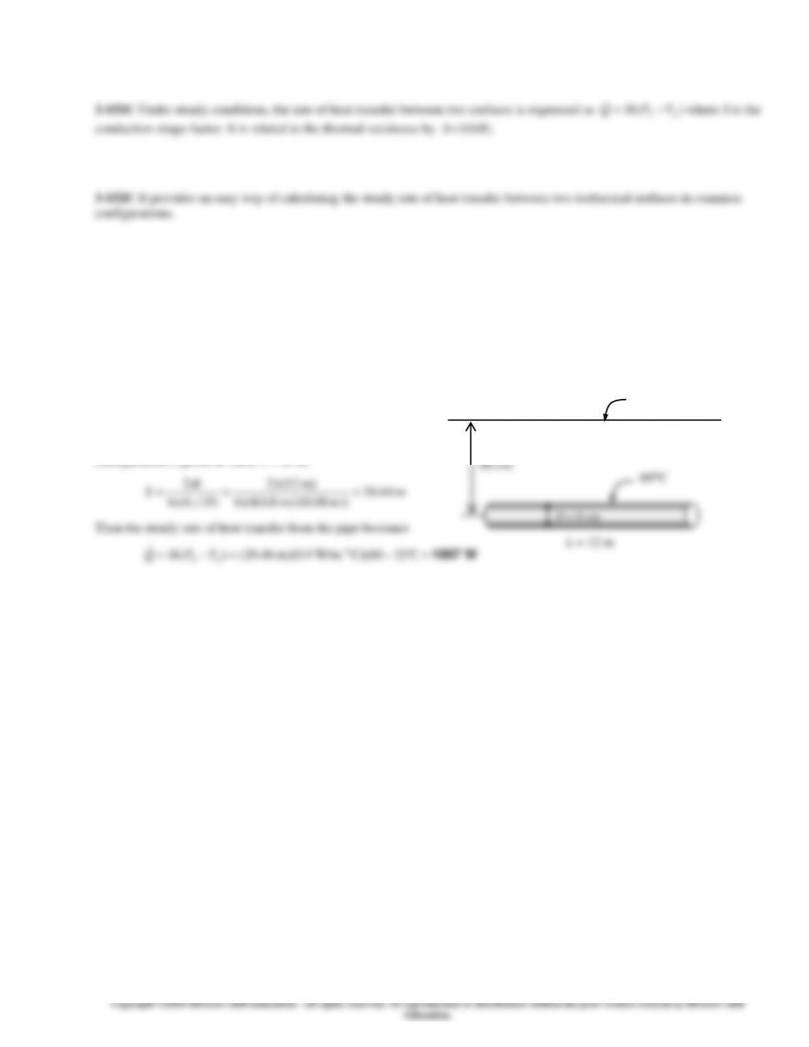
3-153 The hot water pipe of a district heating system is buried in the soil. The rate of heat loss from the pipe is to be
determined.
Assumptions 1 Steady operating conditions exist. 2 Heat transfer is two-dimensional (no change in the axial direction). 3
Thermal conductivity of the soil is constant.
Properties The thermal conductivity of the soil is given
to be k = 0.9 W/m°C.
Analysis Since z >1.5D, the shape factor for this
configuration is given in Table 3-7 to be
m 44.20
)]m 08.0/()m 8.0(4ln[
)m 12(2
)/4ln(
2===
Dz
L
S
Then the steady rate of heat transfer from the pipe becomes
W1067=−=−= C)260)(C W/m.9.0)(m 44.20()( o
21 TTSkQ
60C
L = 12 m
D = 8 cm
2C
80 cm