3-81
3-82
3-98 Liquid NH3 flows in a pipe, which is insulated. The insulation thickness on the pipe that is necessary to keep
the liquid NH3 temperature below −35°C is to be determined.
Assumptions1 Heat transfer is steady since there is no indication of any change with time. 2Heat transfer is one-dimensional
since there is thermal symmetry about the centerline and no variation in the axial direction. 3 Thermal conductivities are
constant. 4 The thermal contact resistance at the interface is negligible.
PropertiesThe thermal conductivities of the pipe and the insulation are given to bekpipe= 25 W/mK andkins = 0.75 W/mK,
respectively.
AnalysisThe thermal resistances of different layers are
LDhAh
R
iii
i
1
11
==
(liq. NH3 convection resistance)
DD
12
)/ln(
“GIVEN”
h_i=100 [W/m^2-K] “liq. NH3 convection heat transfer coefficient”
h_o=20 [W/m^2-K] “ambient air convection heat transfer coefficient”
k_pipe=25 [W/m-K] “pipe thermal conductivity”
k_ins=0.75 [W/m-K] “insulation thermal conductivity”
L=10 [m] “pipe length”
D_1=0.025 [m] “inner pipe diameter”
D_2=0.04 [m] “outer pipe diameter”
T_3=10 [C] “outer insulation surface temperature”
T_i=-35 [C] “liq. NH3 temperature”
T_o=20 [C] “ambient air temperature”
“THERMAL RESISTANCES”
R_i=1/(h_i*pi*D_1*L) “liq. NH3 convection resistance”
R_pipe=ln(D_2/D_1)/(2*pi*k_pipe*L) “pipe layer resistance”
R_ins=ln(D_3/D_2)/(2*pi*k_ins*L) “insulation layer resistance”
R_o=1/(h_o*pi*D_3*L) “ambient air convection resistance”
R_total=R_i+R_pipe+R_ins+R_o
“SOLVING FOR THE INSULATION THICKNESS”
Q_dot=(T_o-T_i)/(R_total)
Q_dot=(T_o-T_3)/(R_o)
t=(D_3-D_2)/2
DiscussionTo keep the liquid NH3 below −35°C, the pipe insulation thickness must be at least 6.3 cm thick.
3-83
3-84
3-100 Ice slurry is being transported in an insulated pipe. The insulation thickness on the pipe that is necessary to
prevent condensation on the outer surface is to be determined.
Assumptions1 Heat transfer is steady since there is no indication of any change with time. 2Heat transfer is one-dimensional
since there is thermal symmetry about the centerline and no variation in the axial direction. 3 Thermal conductivities are
constant. 4 The thermal contact resistance at the interface is negligible.
PropertiesThe thermal conductivities of the pipe and the insulation are given to bekpipe= 15 W/mK andkins = 0.95 W/mK,
respectively.
AnalysisThe thermal resistances of different layers are
Lk
DD
R
pipe
12
pipe 2
)/ln(
=
(pipe layer resistance)
DD
23
)/ln(
“GIVEN”
h_o=10 [W/m^2-K] “ambient air convection heat transfer coefficient”
k_pipe=15 [W/m-K] “pipe thermal conductivity”
3-85
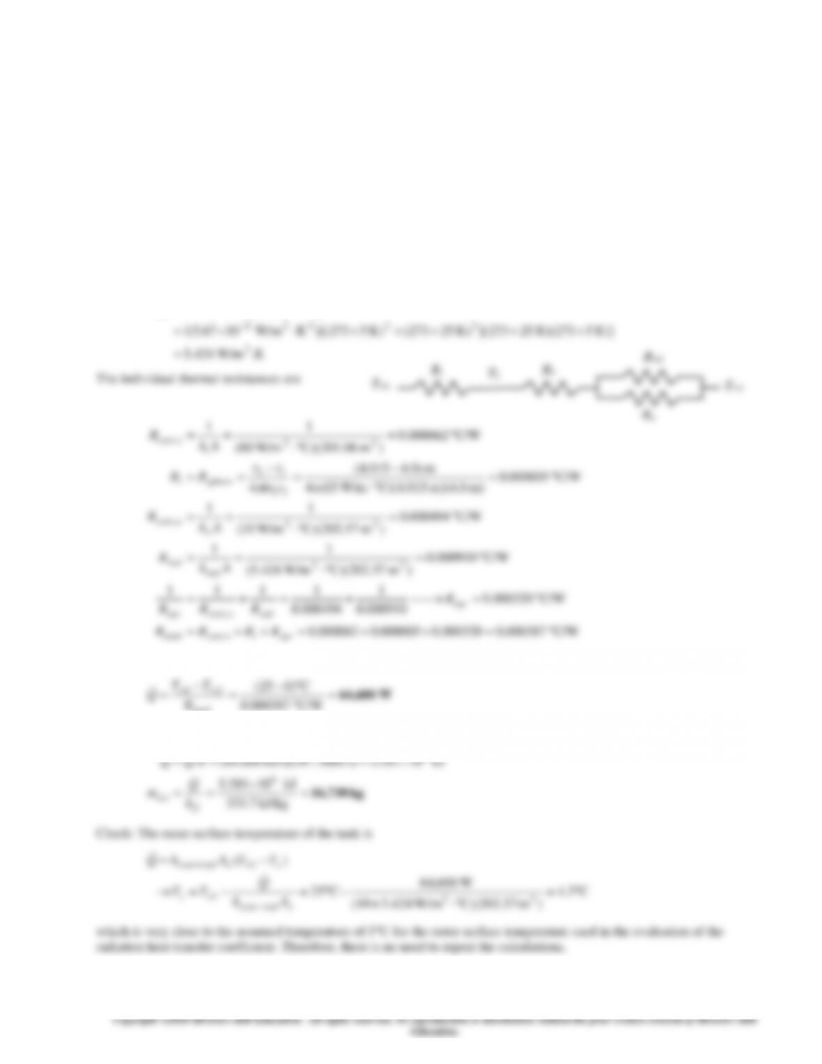
3-101 A spherical container filled with iced water is subjected to convection and radiation heat transfer at its outer surface.
The rate of heat transfer and the amount of ice that melts per day are to be determined.
Assumptions 1 Heat transfer is steady since the specified thermal conditions at the boundaries do not change with time. 2
Heat transfer is one-dimensional since there is thermal symmetry about the midpoint. 3 Thermal conductivity is constant.
Properties The thermal conductivity of steel is given to be k = 15 W/m°C. The heat of fusion of water at 1 atm is
kJ/kg 7.333=
if
h
. The outer surface of the tank is black and thus its emissivity is = 1.
Analysis (a) The inner and the outer surface areas of sphere are
22
2
22
2
m 57.202m) 03.8(
m 06.201m) 8(
===
===
oo
ii
DA
DA
We assume the outer surface temperature T2 to be 5°C after comparing convection heat transfer coefficients at the inner and
the outer surfaces of the tank. With this assumption, the radiation heat transfer coefficient can be determined from
))((
22428
2
22
2
++=
−
surrsurrrad TTTTh
C/W 000387.0000320.0000005.0000062.0
C/W 000320.0
000910.0
1
000494.0
1111
C/W 000910.0
)m 57.202(C) W/m424.5(
11
1,
,
22
=++=++=
=⎯→⎯+=+=
=
==
eqviconvtotal
eqv
radoconveqv
rad
rad
RRRR
R
RRR
Ah
R
Then the steady rate of heat transfer to the iced water becomes
−
−
C)025(
21
TT
3-86
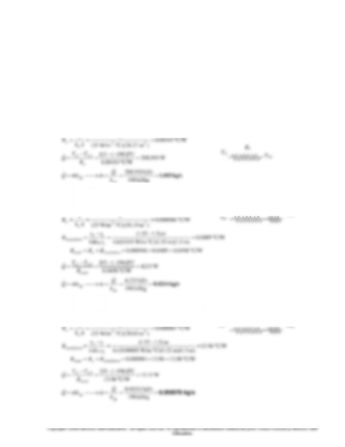
3-102 A spherical tank filled with liquid nitrogen at 1 atm and -196C is exposed to convection and radiation with the
surrounding air and surfaces. The rate of evaporation of liquid nitrogen in the tank as a result of the heat gain from the
surroundings for the cases of no insulation, 5-cm thick fiberglass insulation, and 2-cm thick superinsulation are to be
determined.
Assumptions 1 Heat transfer is steady since the specified thermal conditions at the boundaries do not change with time. 2
Heat transfer is one-dimensional since there is thermal symmetry about the midpoint. 3 The combined heat transfer
coefficient is constant and uniform over the entire surface. 4 The temperature of the thin-shelled spherical tank is said to be
nearly equal to the temperature of the nitrogen inside, and thus thermal resistance of the tank and the internal convection
resistance are negligible.
Properties The heat of vaporization and density of liquid nitrogen at 1 atm are given to be 198 kJ/kg and 810 kg/m3,
respectively. The thermal conductivities are given to be k = 0.035 W/m°C for fiberglass insulation and k = 0.00005 W/m°C
for super insulation.
Analysis (a)The heat transfer rate and the rate of evaporation of the liquid without insulation are
222 m 27.28m) 3( ===
DA
11

3-87
3-103 A spherical tank filled with liquid oxygen at 1 atm and -183C is exposed to convection and radiation with the
surrounding air and surfaces. The rate of evaporation of liquid oxygen in the tank as a result of the heat gain from the
surroundings for the cases of no insulation, 5-cm thick fiberglass insulation, and 2-cm thick superinsulation are to be
determined.
Assumptions 1 Heat transfer is steady since the specified thermal conditions at the boundaries do not change with time. 2
Heat transfer is one-dimensional since there is thermal symmetry about the midpoint. 3 The combined heat transfer
coefficient is constant and uniform over the entire surface. 4 The temperature of the thin-shelled spherical tank is said to be
nearly equal to the temperature of the oxygen inside, and thus thermal resistance of the tank and the internal convection
resistance are negligible.
Properties The heat of vaporization and density of liquid oxygen at 1 atm are given to be 213 kJ/kg and 1140 kg/m3,
respectively. The thermal conductivities are given to be k = 0.035 W/m°C for fiberglass insulation and k = 0.00005 W/m°C
for super insulation.
Analysis (a)The heat transfer rate and the rate of evaporation of the liquid without insulation are
222 m 27.28m) 3( ===
DA
11
3-88
3-89
3-90
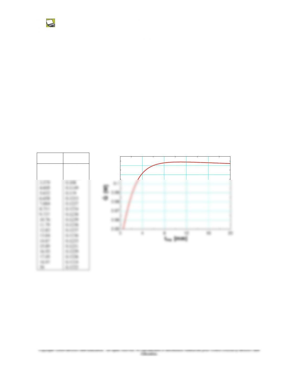
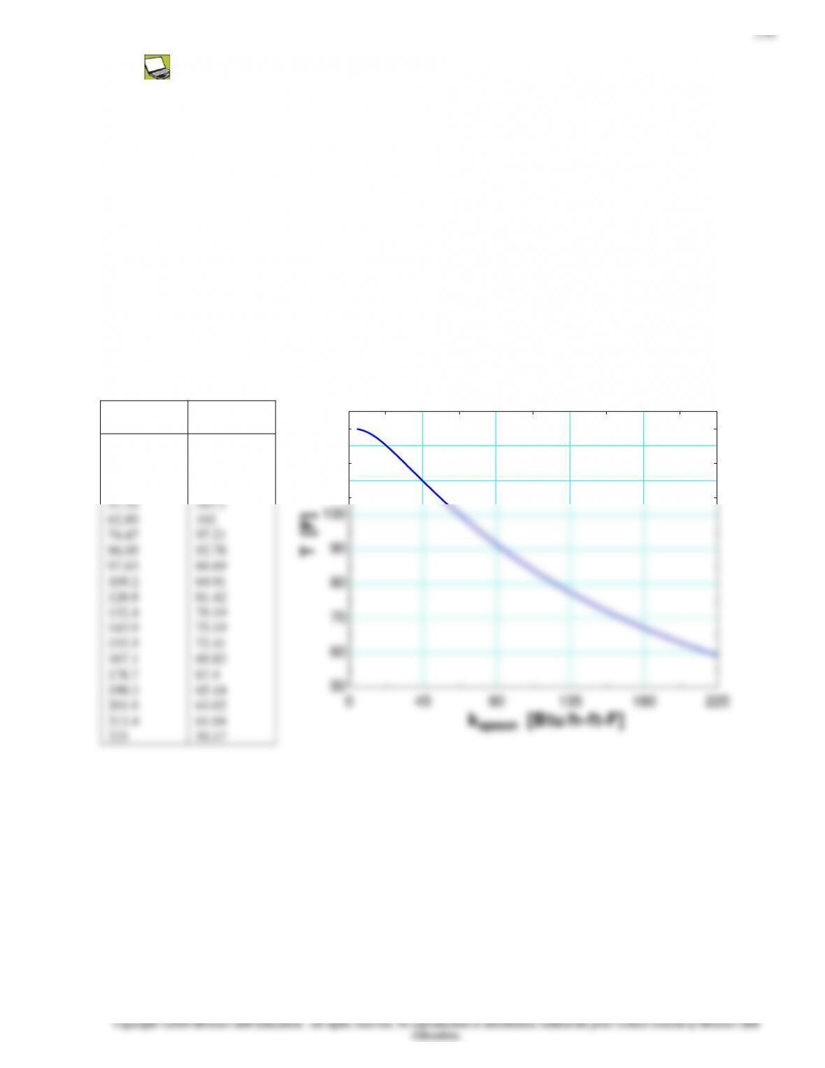
3-112 Prob. 3-111 is reconsidered. The rate of heat transfer from the ball as a function of the plastic insulation
thickness is to be plotted.
Analysis The problem is solved using EES, and the solution is given below.
“GIVEN”
D_1=0.004 [m]
t_ins=1 [mm]
k_ins=0.13 [W/m-C]
T_ball=50 [C]
T_infinity=15 [C]
h_o=20 [W/m^2-C]
“ANALYSIS”
D_2=D_1+2*t_ins*Convert(mm, m)
A_o=pi*D_2^2
R_conv_o=1/(h_o*A_o)
R_ins=(r_2-r_1)/(4*pi*r_1*r_2*k_ins)
r_1=D_1/2
r_2=D_2/2
R_total=R_conv_o+R_ins
Q_dot=(T_ball-T_infinity)/R_total
tins
[mm]
Q
[W]
0.5
1.526
2.553
3.579
4.605
5.632
6.658
7.684
8.711
9.737
10.76
11.79
12.82
13.84
14.87
15.89
16.92
17.95
18.97
20
0.05016
0.07736
0.09626
0.108
0.1149
0.119
0.1213
0.1227
0.1234
0.1238
0.1239
0.1238
0.1237
0.1236
0.1233
0.1231
0.1229
0.1226
0.1224
0.1222
0 4 8 12 16 20
0.05
0.06
0.07
0.08
0.09
0.1
0.11
0.12
0.13
tins [mm]
Q [W]
3-91
Heat Transfer from Finned Surfaces
3-113C Fins should be attached to the outside since the heat transfer coefficient inside the tube will be higher due to forced
3-115C The fin efficiency is defined as the ratio of actual heat transfer rate from the fin to the ideal heat transfer rate from the
3-117C Fins enhance heat transfer from a surface by increasing heat transfer surface area for convection heat transfer.
3-118C Effectiveness of a single fin is the ratio of the heat transfer rate from the entire exposed surface of the fin to the heat
3-121C If the fin is too long, the temperature of the fin tip will approach the surrounding temperature and we can neglect heat
3-92
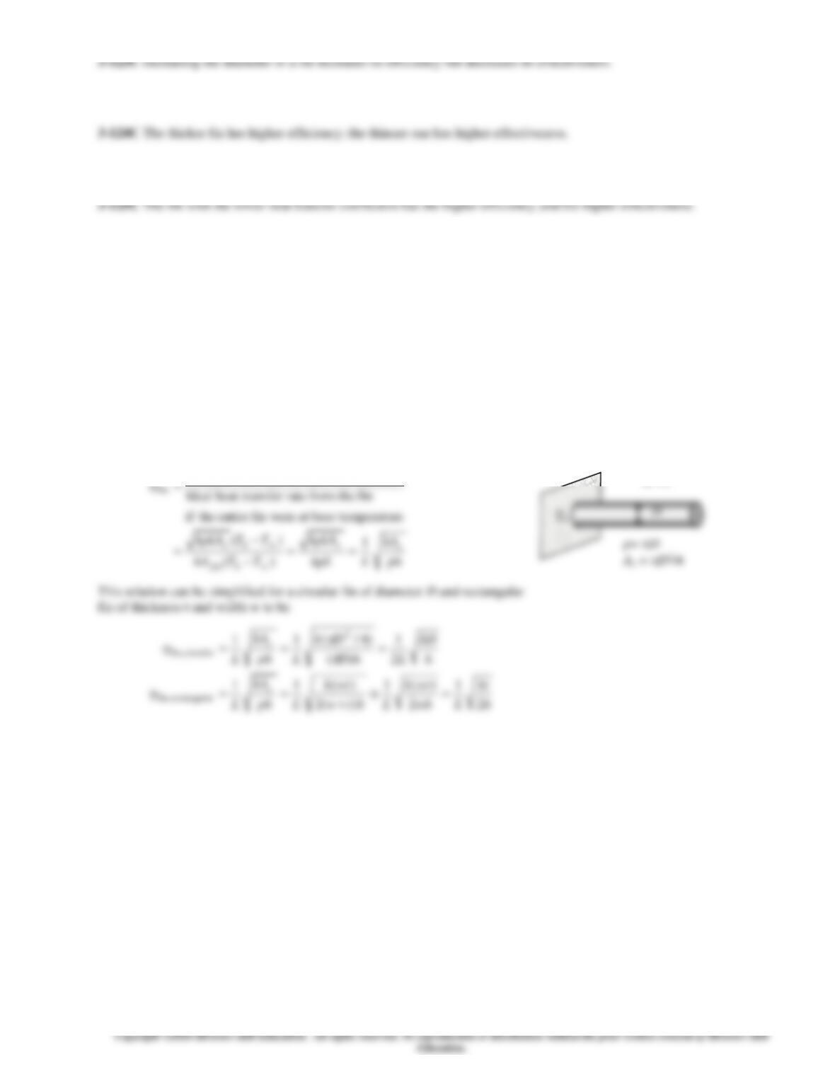
3-126 A relation is to be obtained for the fin efficiency for a fin of constant cross-sectional area
c
A
, perimeter p, length L,
and thermal conductivity k exposed to convection to a medium at
T
with a heat transfer coefficient h. The relation is to be
simplified for circular fin of diameter D and for a rectangular fin of thickness t.
Assumptions 1T fins are sufficiently long so that the temperature of the fin at the tip is nearly
T
. 2 Heat transfer from the
fin tips is negligible.
Analysis Taking the temperature of the fin at the base to be
T
b
and using the heat transfer relation for a long fin, fin efficiency
for long fins can be expressed as
fin thefrom ratefer heat trans Ideal
fin thefrom ratefer heat trans Actual
fin
=
h, T
D
Tb
3-93
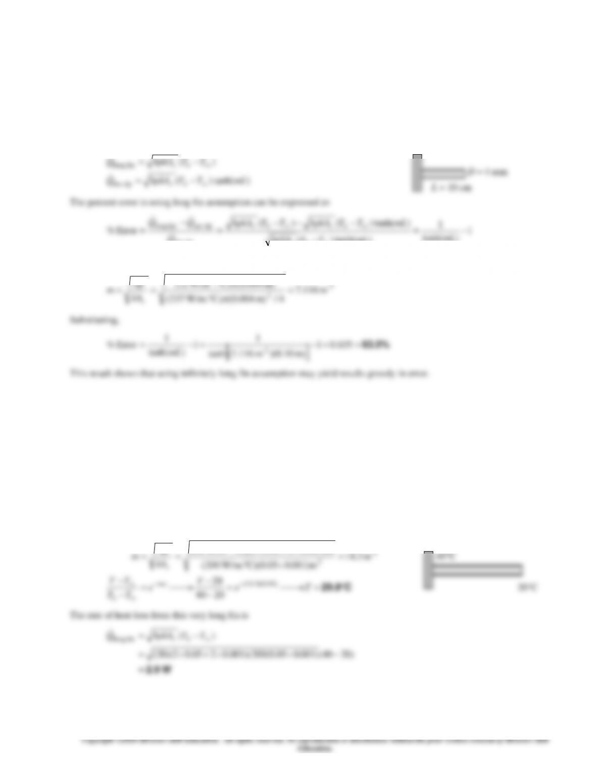
3-127 A fin is attached to a surface. The percent error in the rate of heat transfer from the fin when the infinitely long fin
assumption is used instead of the adiabatic fin tip assumption is to be determined.
Assumptions 1 Steady operating conditions exist. 2 The temperature along the fins varies in one direction only (normal to the
plate). 3 The heat transfer coefficient is constant and uniform over the entire fin surface. 4 The thermal properties of the fins
are constant. 5 The heat transfer coefficient accounts for the effect of radiation from the fins.
Properties The thermal conductivity of the aluminum fin is given to be k = 237 W/m°C.
Analysis The expressions for the heat transfer from a fin under infinitely long fin
and adiabatic fin tip assumptions are
)(
fin long
TThpkAQ
bc
−=
3-94
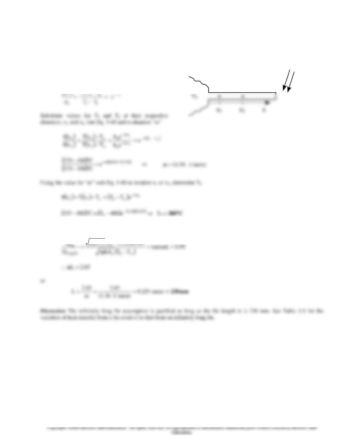
3-129 A very long rod has one end maintained at Tb and the other end isexposed to air at 400C. Thermocouples imbedded in
the rod at locations 25 and 120 mm from the base surface register temperatures of 325C and 375C, respectively. (a)
Calculate the rod base temperature (C) and (b) Determine the rod length (mm) for the case where the ratio of the heat
transfer from a finite length fin to the heat transfer from a very long fin under the same conditions is 99%.
Assumptions 1 Steady-state conditions. 2 Rod is infinitely long with uniform cross-sectional area. 3 Uniform convection
coefficient along the rod.
Analysis (a) For an infinitely long fin, use Eq. 3–60
x1
x2
( ) ( )
mx
x T x T
q
¥–
–
( ) ( )
( )
025.056.11
be400TC400325 −
−=−
Tb = 300C
(b) From Eq. 3-83
( )
mLtanhTThpkA
Q
bc
fin ==
−
T1
T2
Air
T
3-95
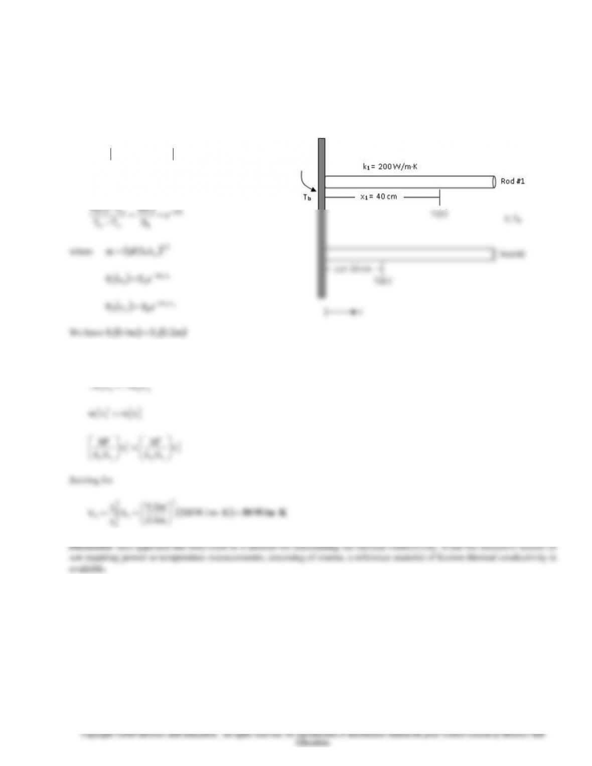
3-130 Positions of equal temperature on two long rods of the same diameter and length,but different thermal conductivity,
which are exposed to the same base temperature and ambient condition.
Assumptions 1 Steady-state conditions. 2 Rods are infinitely long fins of uniform cross-sectional area. 3 Uniform convection
coefficient along the rods. 4 Constant properties.
Properties The thermal conductivity for the aluminum rod is k1 = 200 W/m·K.
Analysis
For very long fins (case 1), use Eq. 3-60
( ) ( )
mx
bb
e
x
TT
TxT −
=
=
−
−
where
( )
21
c
kAhPm=
( )
11xm
b11 ex −
=
( )
22 xm
b22 ex −
=
We have
( ) ( )
m2.0m4.0 21 =
Then
2211 xm
b
xm
bee −− =
( )
K W/m50 =
== Km/W200
m4.0
m2.0
k
x
x
k
2
1
2
1
2
2
2
( ) ( )
cm20x
2
cm40x
121
xTxT == =
3-96
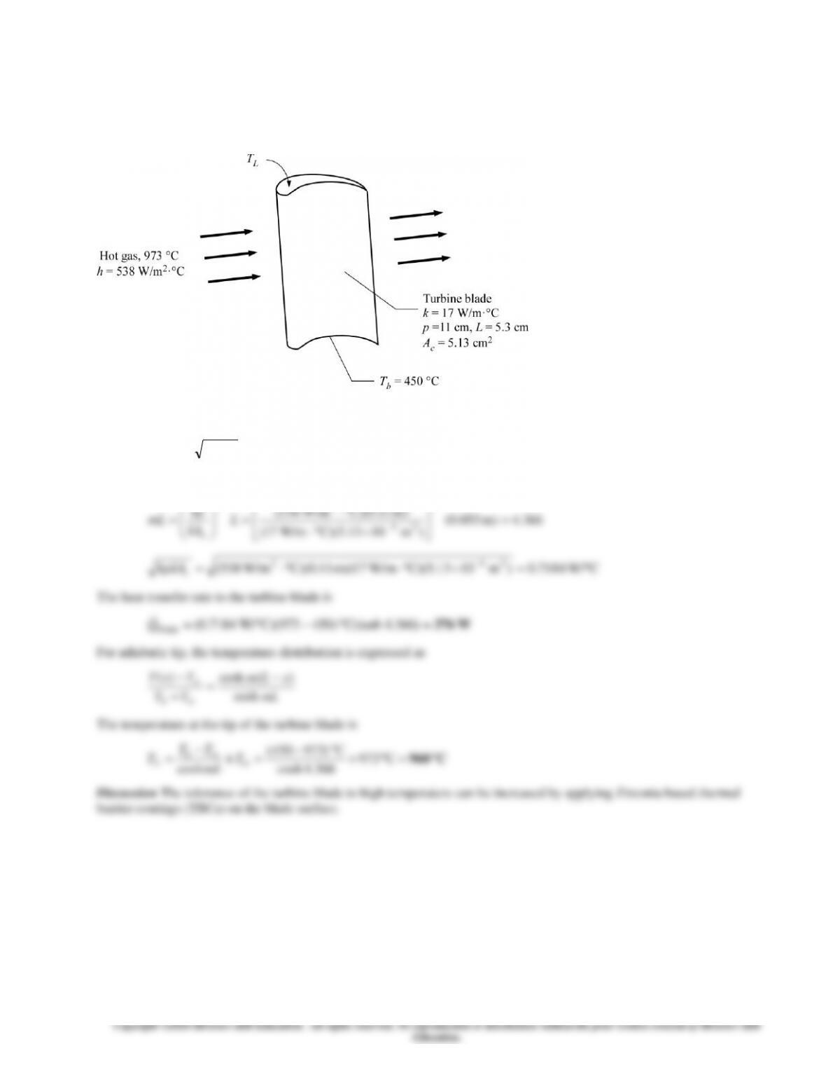
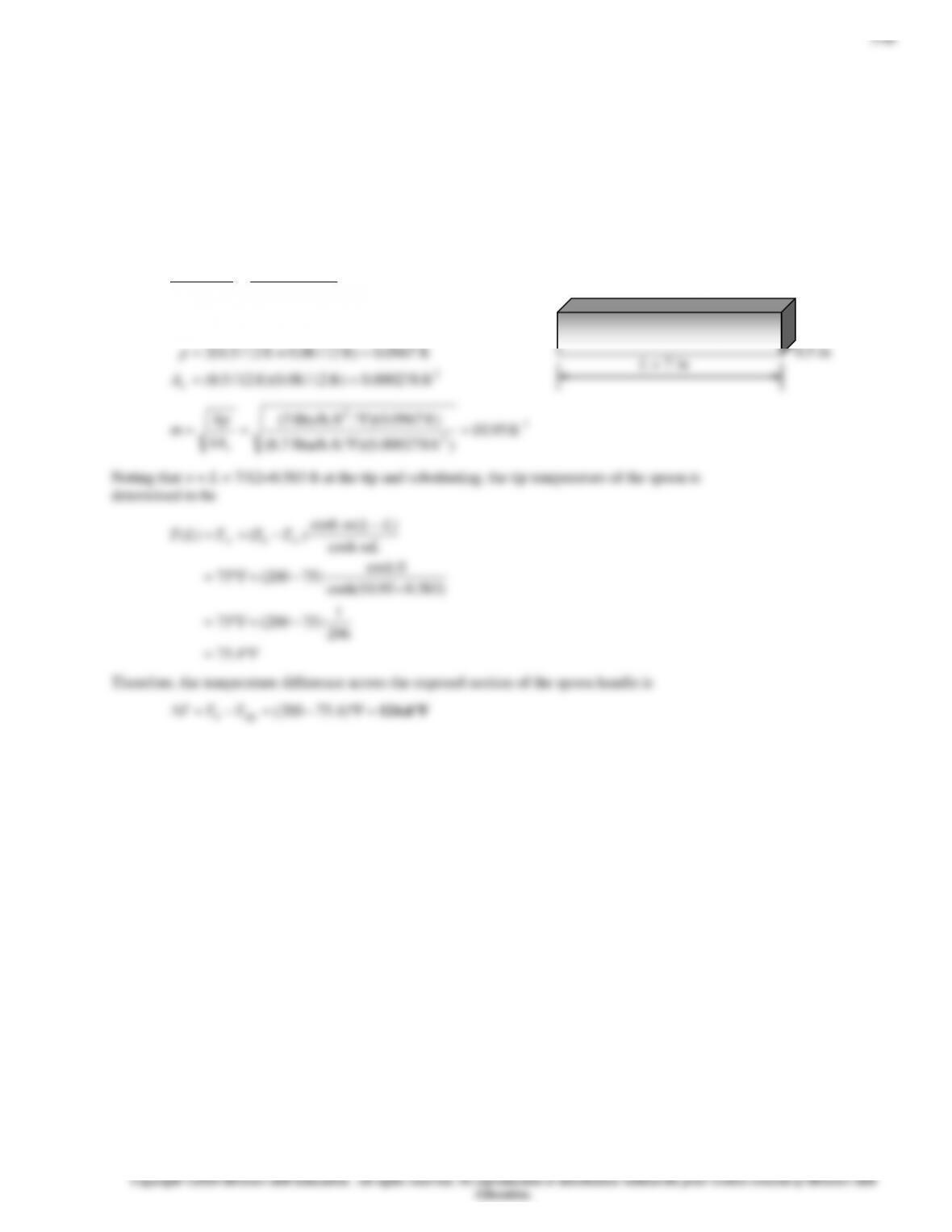
3-131 A turbine blade is exposed to hot gas from the combustion chamber. The heat transfer rate to the turbine blade and the
temperature at the tip are to be determined.
Assumptions1 Heat conduction is steady and one-dimensional. 2 Thermal properties are constant. 3 Heat transfer by radiation
is negligible. 4 The cross-sectional area of the turbine blade is uniform.
Properties The thermal conductivity of the turbine blade is given as 17 W/m ∙ °C.
Analysis The turbine blade can be treated as a uniform cross section fin with adiabatic tip. The heat transfer rate to the turbine
blade can be expressed as
mLTThpkAQ bc tanh)(
blade −=
where
)m 11.0)(C W/m538(5.0
2
5.0
hp
3-97
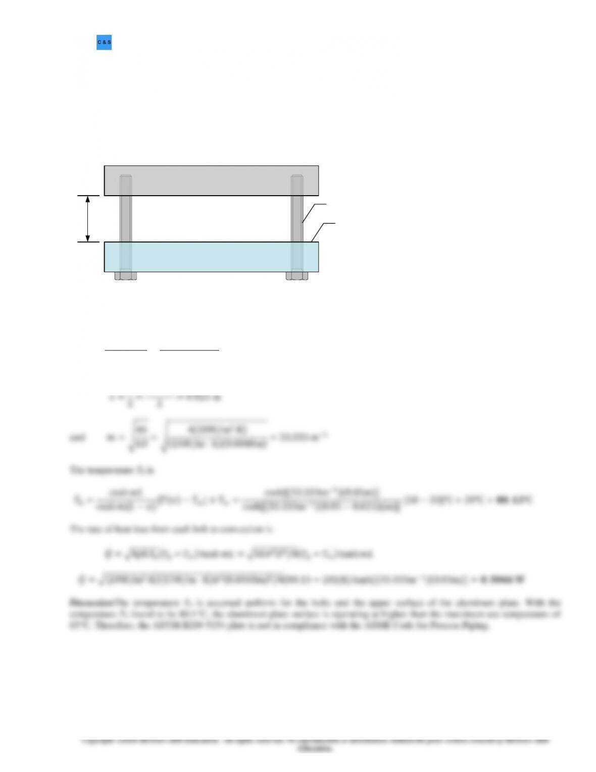
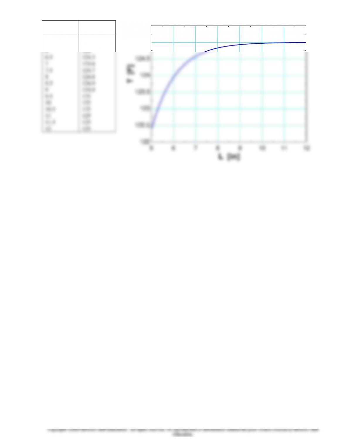
3-132 An ASTM B209 5154 aluminum alloy plate is connected to an insulation plate by long metal bolts. Portion of the
bolts are exposed to convection with ambient air. The temperature of the bolt at mid-length is known. The surface
temperature at the base Tb and the heat transfer rate from each bolt are to be determined. Is the use of the ASTM B209 5154
plate in compliance with the ASME Code for Process Piping, which has a maximum use temperature of 65°C?
Assumptions1 Heat transfer is steady. 2 The portion of the bolt exposed to convection behaves as finned surface. 3 The
temperature Tb is uniform for the aluminum plate surface and bolts. 4 Thermal properties are constant. 5 The tip of the bolt is
adiabatic.
Properties The thermal conductivity for the bolts is 15 W/m·K.
Insulation
Air, T∞, h Tb
Aluminum plate
L
Bolt
Analysis The bolts can be treated as pin fins of rectangular profile. Since the bolts are attached to an insulation plate, the tip
of the bolts can be treated as adiabatic. The equation for an adiabatic fin tip is
𝑇(𝑥)−𝑇∞
𝑇𝑏−𝑇∞=cosh𝑚(𝐿−𝑥)
cosh𝑚𝐿
where
3-98
3-99
3-100
L
[in]
T
[F]
5
5.5
6
6.5
7
7.5
8
8.5
9
9.5
10
10.5
11
11.5
12
122.4
123.4
124
124.3
124.6
124.7
124.8
124.9
124.9
125
125
125
125
125
125
5 6 7 8 9 10 11 12
122
122.5
123
123.5
124
124.5
125
125.5
L [in]
DT [F]