11-2
Types of Heat Exchangers
11–1C Heat exchangers are classified according to the flow type as parallel flow, counter flow, and cross-flow arrangement.
11-2C A heat exchanger is classified as being compact if
> 700 m2/m3 or (200 ft2/ft3) where is the ratio of the heat
11-3C Regenerative heat exchanger involves the alternate passage of the hot and cold fluid streams through the same flow
area. The static type regenerative heat exchanger is basically a porous mass which has a large heat storage capacity, such as a
11-4C In the shell and tube exchangers, baffles are commonly placed in the shell to force the shell side fluid to flow across
11-6C Using so many tubes increases the heat transfer surface area which in turn increases the rate of heat transfer.
11-7C In counter-flow heat exchangers, the hot and the cold fluids move parallel to each other but both enter the heat
exchanger at opposite ends and flow in opposite direction. In cross-flow heat exchangers, the two fluids usually move
11-3
The Overall Heat Transfer Coefficient
11-8C Heat is first transferred from the hot liquid to the wall by convection, through the wall by conduction and from the
wall to the cold liquid again by convection.
11-9C When the wall thickness of the tube is small and the thermal conductivity of the tube material is high, which is usually
the case, the thermal resistance of the tube is negligible.
soi AAA
11-11C The effect of fouling on a heat transfer is represented by a fouling factor Rf. Its effect on the heat transfer coefficient
11–13C When one of the convection coefficients is much smaller than the other
oi hh <<
, and
si AAA 0
. Then we have (
oi hh /1>>/1
) and thus
ii hUUU == 0
.
11–14C The most common type of fouling is the precipitation of solid deposits in a fluid on the heat transfer surfaces.
11-15C When the wall thickness of the tube is small and the thermal conductivity of the tube material is high, the thermal
11-4
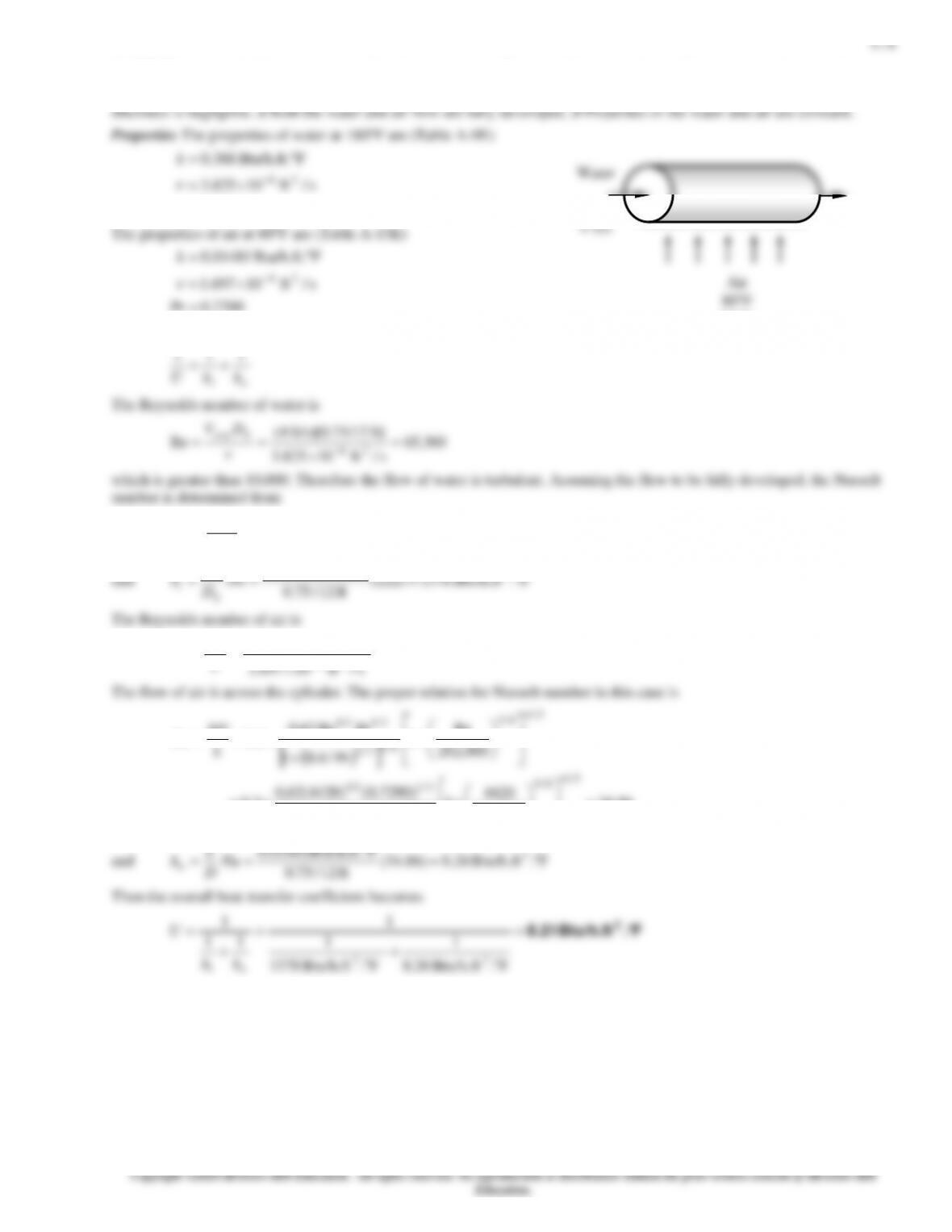
11–16E The overall heat transfer coefficients based on the outer and inner surfaces for a heat exchanger are to be determined.
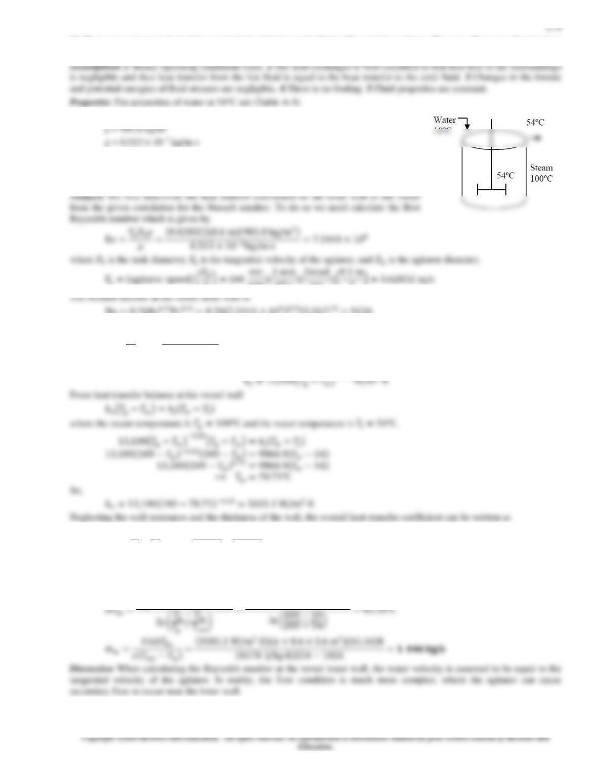
Assumptions 1 Steady operating condition exists. 2 Thermal properties are constant.
Properties The conductivity of the tube material is given to be 0.5 Btu/hr·ft·°F.
Analysis The overall heat transfer coefficient based on the outer surface is
1
111 ++=
11-5
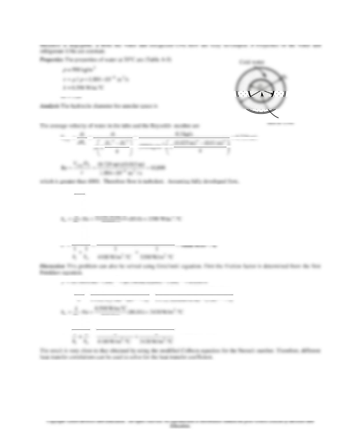
11–17 Refrigerant-134a is cooled by water in a double-pipe heat exchanger. The overall heat transfer coefficient is to be
determined.
Assumptions 1 The thermal resistance of the inner tube is negligible since the tube material is highly conductive and its
m 015.001.0025.0 =−=−= ioh DDD
Hot R-134a
11-7
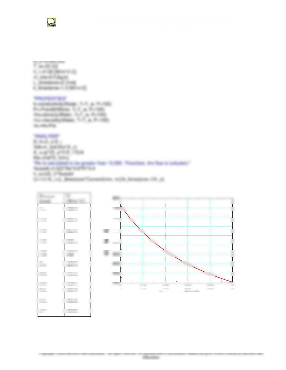
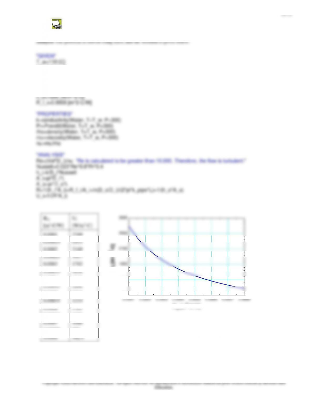
11–19 Prob. 11-18 is reconsidered. The overall heat transfer coefficient as a function of the limestone thickness is to be
plotted.
Analysis The problem is solved using EES, and the solution is given below.
“GIVEN”
D_i=0.010 [m]
2.1
2.3
2.5
2.7
463.4
432.6
405.6
381.8
1 1.4 1.8 2.2 2.6 3
400
450
Llimestone [mm]
11–10
11-22E The overall heat transfer coefficient of a heat exchanger and the percentage change in the overall heat transfer
coefficient due to scale built-up are to be determined.
Assumptions 1 Steady operating condition exists. 2 The heat transfer coefficients and the fouling factors are constant and
uniform.
Analysis When operating at design and clean conditions, the overall heat transfer coefficient is given as
11–12
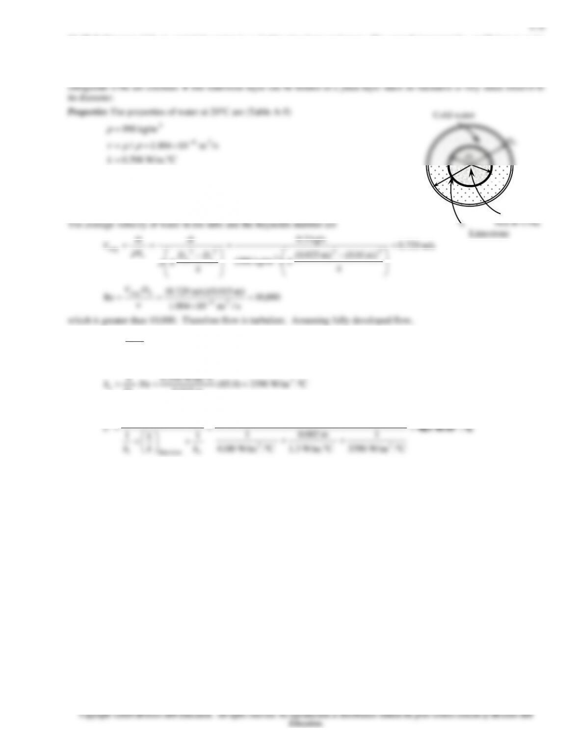
11–24 Water is flowing through the tubes in a boiler. The overall heat transfer coefficient of this boiler based on the inner
surface area is to be determined.
Assumptions 1 Water flow is fully developed. 2 Properties of water are constant. 3 The heat transfer coefficient and the
58.1Pr
=
Analysis The Reynolds number is
m) m/s)(0.01 5.3(
avg =
h
DV
11–14
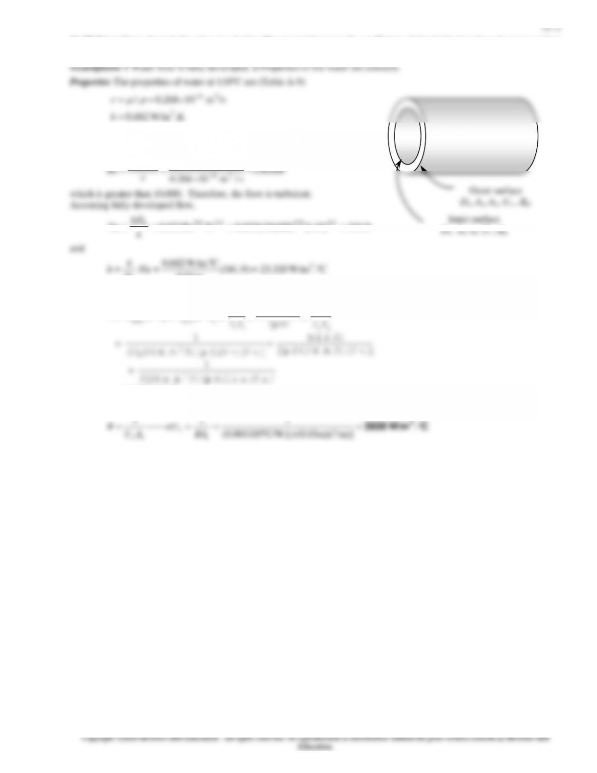
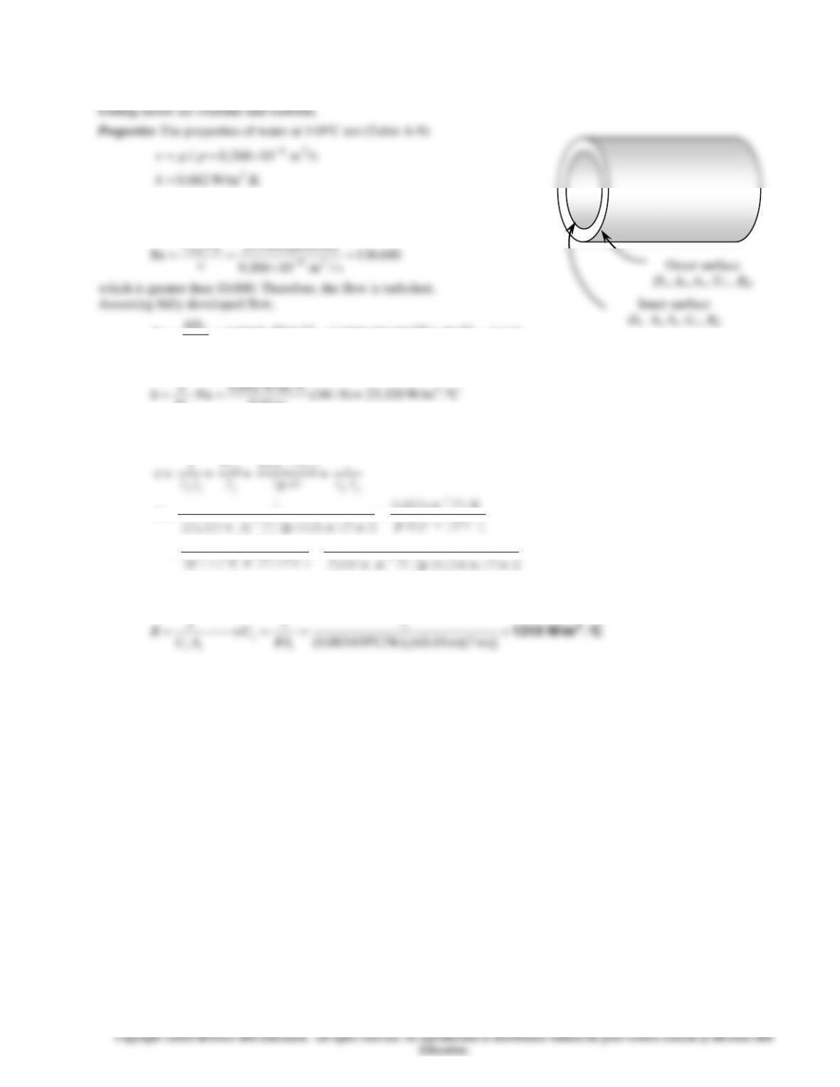
11–26 The heat transfer coefficients and the fouling factors on tube and shell side of a heat exchanger are given. The thermal
resistance and the overall heat transfer coefficients based on the inner and outer areas are to be determined.
Assumptions 1 The heat transfer coefficients and the fouling factors are constant and uniform.
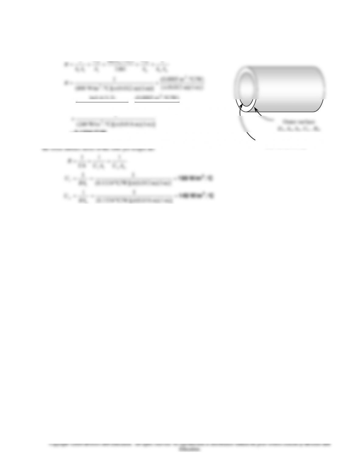
Analysis (a) The total thermal resistance of the heat exchanger per unit length is
C/W0.1334=
+
+
+
+
=
++++=
m)] m)(1 016.0([C). W/m240(
1
m)] m)(1 016.0([
C/W).m 0002.0(
m) C)(1 W/m.380(2
)2.1/6.1ln(
m)] m)(1 012.0([
C/W).m 0005.0(
m)] m)(1 012.0([C). W/m800(
1
1
2
)/ln(
1
2
2
2
2
R
AhA
R
kL
DD
A
R
Ah
R
ooo
fo
io
i
fi
ii
(b) The overall heat transfer coefficient based on the inner and
Outer surface
Do, Ao, ho, Uo , Rfo
Inner surface
Di, Ai, hi, Ui , Rfi
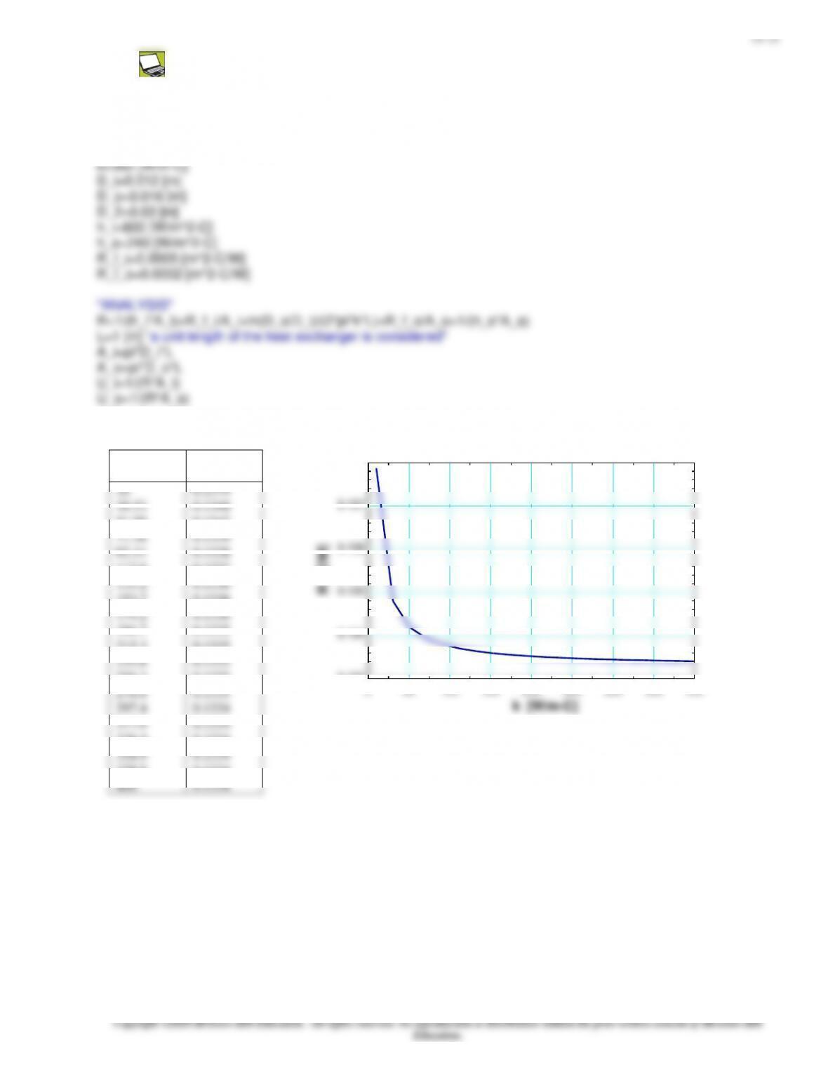
11–16
hi
[W/m2–C]
R
[C/W]
500
550
600
650
700
750
800
850
900
950
1000
1050
1100
1150
1200
1250
1300
1350
1400
1450
1500
0.1533
0.1485
0.1445
0.1411
0.1381
0.1356
0.1334
0.1315
0.1297
0.1282
0.1268
0.1255
0.1244
0.1233
0.1224
0.1215
0.1207
0.1199
0.1192
0.1185
0.1179
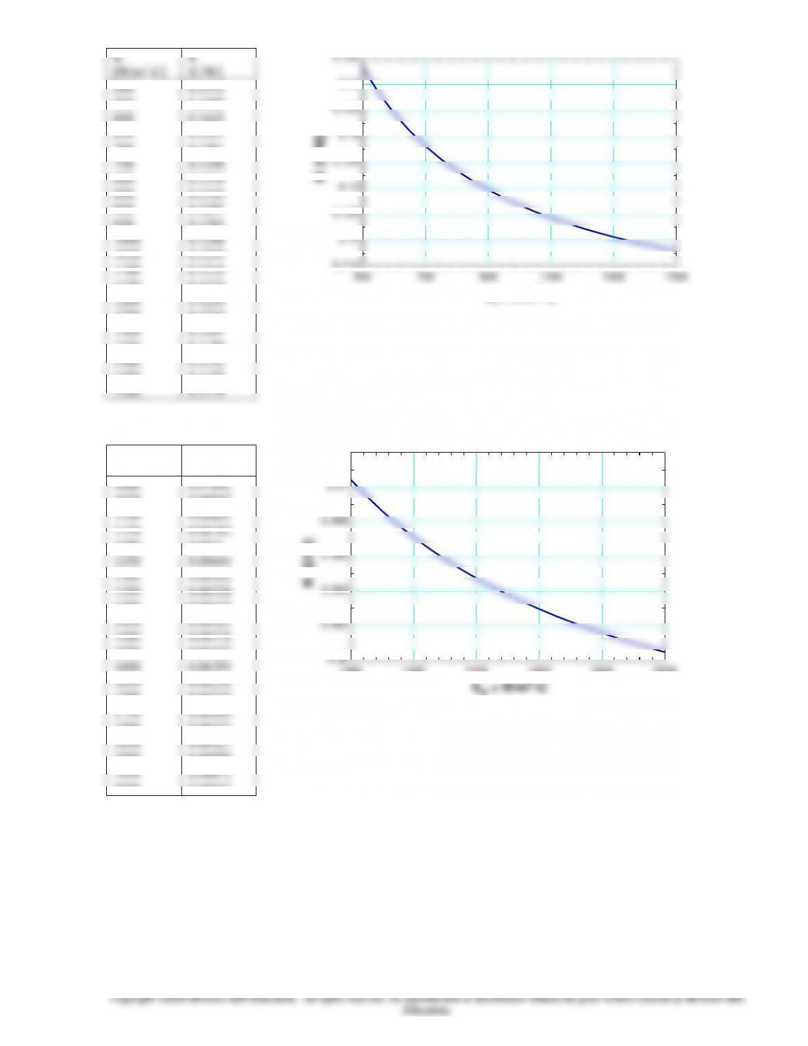
ho
[W/m2–C]
R
[C/W]
1000
1050
1100
1150
1200
1250
1300
1350
1400
1450
1500
1550
1600
1650
1700
1750
1800
1850
1900
2000
0.07041
0.06947
0.06861
0.06782
0.0671
0.06644
0.06582
0.06526
0.06473
0.06424
0.06378
0.06335
0.06295
0.06258
0.06222
0.06189
0.06157
0.06127
0.06099
0.06047
500 700 900 1100 1300 1500
0.115
0.12
0.125
0.13
0.135
0.14
0.145
0.15
0.155
hi = W/m2-C
R [C/W]
1000 1200 1400 1600 1800 2000
0.06
0.062
0.064
0.066
0.068
0.07
0.072
R [C/W]
ho = W/m2-C
11–18
For water,
( )
01728.064.1)120980ln(79.0 2=−= −
f
11–19
Analysis of Heat Exchangers
11-29C The heat exchangers usually operate for long periods of time with no change in their operating conditions, and then
they can be modeled as steady-flow devices. As such , the mass flow rate of each fluid remains constant and the fluid
11-30C That relation is valid under steady operating conditions, constant specific heats, and negligible heat loss from the heat
exchanger.
11–20
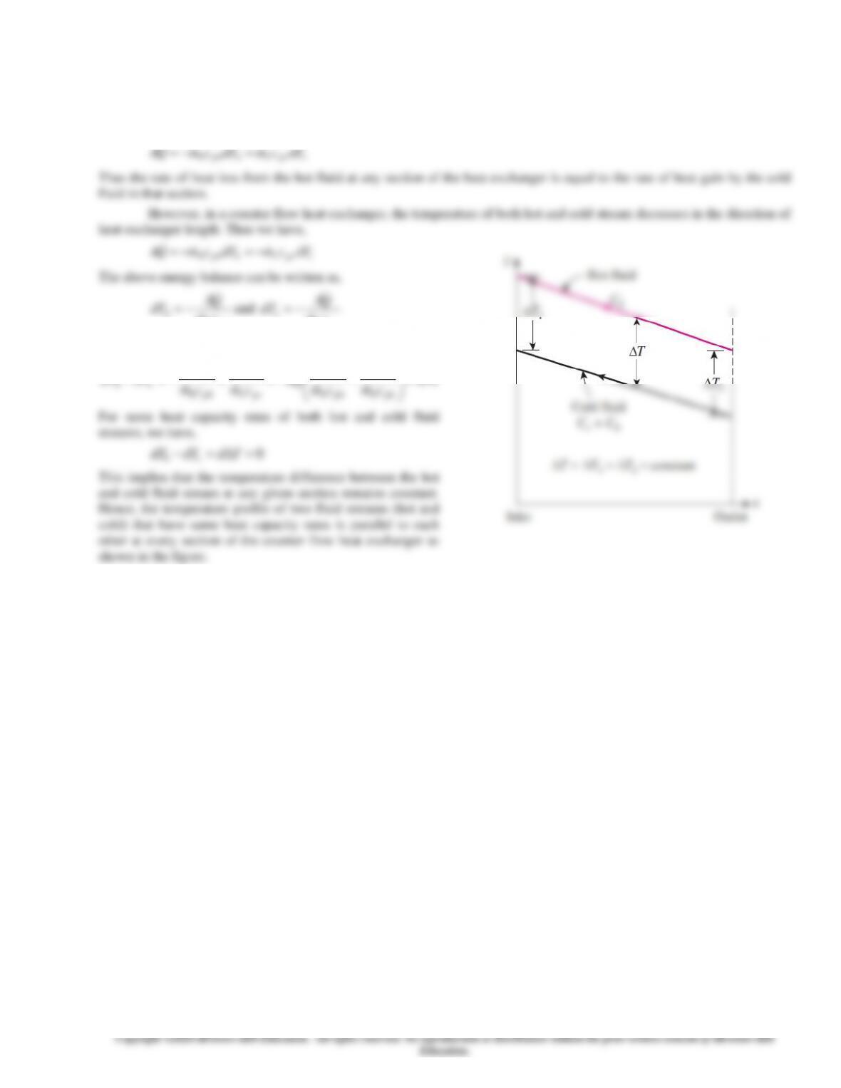
11-34 Hot and cold fluid streams have same heat capacity rates. It is to be proved that the temperature profiles of the hot and
cold fluids are parallel to each other at any given section of the heat exchanger.
Assumption 1 Heat exchanger is well insulated. 2 Fluid properties do not change with heat exchanger length.
Analysis Assuming heat exchanger to be well insulated and the heat transfer occurs only between the hot and cold fluid, the
heat transfer across the differential section of the heat exchanger can be expressed as,
cpcchphhdTcmdTcmQ
=−=
Thus the rate of heat loss from the hot fluid at any section of the heat exchanger is equal to the rate of heat gain by the cold
fluid in that section.
However, in a counter flow heat exchanger, the temperature of both hot and cold stream decreases in the direction of
heat exchanger length. Thus we have,
cpcchphhdTcmdTcmQ
−=−=
The above energy balance can be written as,
phh
hcm
Q
dT
−=
and
pcc
ccm
Q
dT
−=
Thus we get,
Td
cmcm
Q
cm
Q
cm
Q
dTdT
phhphhpccphh
ch =
−−=+−=−
11