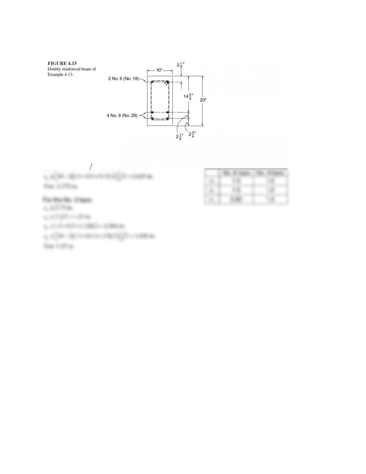
6.1 through 6.6 (based on the beam in Fig. 4.15, Example 4.13, fy = 60 ksi)
For the No. 6 bars:
( )
2.5 in.
1.5 0.5 0.75 2 2.375 in.
10 2 1.5 0.5 0.75 2 2 2.625 in.
Use: 2.375 in.
b
b
b
c
c
c
≤
≤++ =
≤ − ++ =
For the No. 9 bars:
( )
2.75 in.
2.5 2 1.25 in.
1.5 0.5 1.128 2 2.564 in.
10 2 1.5 0.5 1.128 2 2 2.436 in.
Use: 1.25 in.
b
b
b
b
c
c
c
c
≤
≤=
≤++ =
≤ − ++ =
No. 6 bars
No. 9 bars
t
ψ
1.3
1.0
e
ψ
1.0 1.0
s
ψ
0.80
1.0
6.1 For the beam cross section shown in Fig. 4.15, what are the development lengths of the top No. 6
bars and bottom No. 9 bars for No. 4 (No. 13) stirrups with
1
½ in. clear side cover spaced at 6 in.
using Eq. (6.4) and (6.5). Normalweight concrete,
c
f′=
4000 psi. Comment.
No. 6 bars: Plane of splitting through side cover, s = 6 in., n = 1, Atr = 0.2 in2.
t
ψ
= 1.3,
e
ψ
= 1.0,
s
ψ
= 0.80,
λ
= 1.0,
b
c
= 2.375 in.
( ) ( )
40 40 0.20 6 1 1.333
tr tr
K A sn= = × ×=
2.375 1.333
4.94 2.5
0.75
b tr
b
cK
d
++
= = ≤
Eq. (6.4):
3 3 60,000 1.3 1.0 0.8 0.75 22.2 in. 12.0 in.
40 40 2.5
λ 1 4000
ytes
db
b tr
c
b
fd
cK
f
d
ψψψ
××
= = = ≥
′+×
Eq. (6.5):
60,000 1.3 1.0 0.75 37.0 in. 12.0 in.
25λ 25 1 4000
yte
db
c
fd
f
ψψ
××
= = = ≥
′××
No. 9 bars: Plane of splitting between bars separated vertically with 2½–in. center–to center spacing, s = 6
t
e
s
ψ
ψ
6.2 For the beam cross section shown in Fig. 4.15, what are the development lengths of the top No. 6
bars and bottom No. 9 bars for No. 4 (No. 13) stirrups with
1
½ in. clear side cover spaced at 4 in.
using Eq. (6.4) and (6.5). Lightweight concrete,
c
f′=
4000 psi. Comment.
No. 6 bars: Plane of splitting through side cover, s = 4 in., n = 1, Atr = 0.2 in2.
t
ψ
= 1.3,
e
ψ
= 1.0,
s
ψ
= 0.80,
λ
= 0.75,
b
c
= 2.375 in.
( ) ( )
40 40 0.20 4 1 2.0
tr tr
K A sn= = × ×=
2.375 2.0
5.83 2.5
0.75
b tr
b
cK
d
++
= = ≤
Eq. (6.4):
3 3 60,000 1.3 1.0 0.8 0.75 29.6 in. 12.0 in.
40 40 2.5
λ 0.75 4000
ytes
db
b tr
c
b
fd
cK
f
d
ψψψ
××
= = = ≥
′+×
Eq. (6.5):
60,000 1.3 1.0 0.75 49.3 in. 12.0 in.
25λ 25 0.75 4000
yte
db
c
fd
f
ψψ
××
= = = ≥
′××
No. 9 bars: Plane of splitting between bars separated vertically with 2½–in. center–to center spacing, s = 4
t
e
s
b
ψ
ψ
6.3 For the beam cross section shown in Fig. 4.15, what are the development lengths of the top No. 6
bars and bottom No. 9 bars for No. 4 (No. 13) stirrups with
1
½ in. clear side cover spaced at 6 in.
using Eq. (6.4) and (6.5). Normalweight concrete,
c
f′=
8000 psi. Comment.
No. 6 bars: Plane of splitting through side cover, s = 6 in., n = 1, Atr = 0.2 in2.
t
ψ
= 1.3,
e
ψ
= 1.0,
s
ψ
= 0.80,
λ
= 1.0,
b
c
= 2.375 in.
( ) ( )
40 40 0.20 6 1 1.333
tr tr
K A sn= = × ×=
2.375 1.333
4.94 2.5
0.75
b tr
b
cK
d
++
= = ≤
Eq. (6.4):
3 3 60,000 1.3 1.0 0.8 0.75 15.7 in. 12.0 in.
40 40 2.5
λ 1 8000
ytes
db
b tr
c
b
fd
cK
f
d
ψψψ
××
= = = ≥
′+×
Eq. (6.5):
60,000 1.3 1.0 0.75 26.1 in. 12.0 in.
25λ 25 1 8000
yte
db
c
fd
f
ψψ
××
= = = ≥
′××
No. 9 bars: Plane of splitting between bars separated vertically with 2½–in. center–to center spacing, s = 6
t
e
s
ψ
ψ

6.4 For the beam cross section shown in Fig. 4.15, what are the development lengths of the top No. 6
bars and bottom No. 9 bars for No. 4 (No. 13) stirrups with
1
½ in. clear side cover spaced at 6 in.
using Eq. (6.4) and (6.5). Normalweight concrete,
c
f′=
8000 psi. Comment.
No. 6 bars: Plane of splitting through side cover, s = 6 in., n = 1, Atr = 0.2 in2.
t
ψ
= 1.3,
e
ψ
= 1.0,
s
ψ
= 0.80,
λ
= 0.75,
b
c
= 2.375 in.
( ) ( )
40 40 0.20 6 1 1.333
tr tr
K A sn= = × ×=
t
e
s
b
( ) ( )
40 40 0.20 6 2 0.667
tr tr
K A sn= = × ×=
1.25 0.667
1.7 2.5
1.128
b tr
b
cK
d
++
= = ≤
Eq. (6.4):
3 3 60,000 1.0 1.0 1.0 1.128 44.5 in. 12.0 in.
40 40 1.7
λ 0.75 8000
ytes
db
b tr
c
b
fd
cK
f
d
ψψψ
××
= = = ≥
′+×
Eq. (6.5):
60,000 1.0 1.0 1.128 50.4 in. 12.0 in.
20λ 20 0.75 8000
yte
db
c
fd
f
ψψ
××
= = = ≥
′××
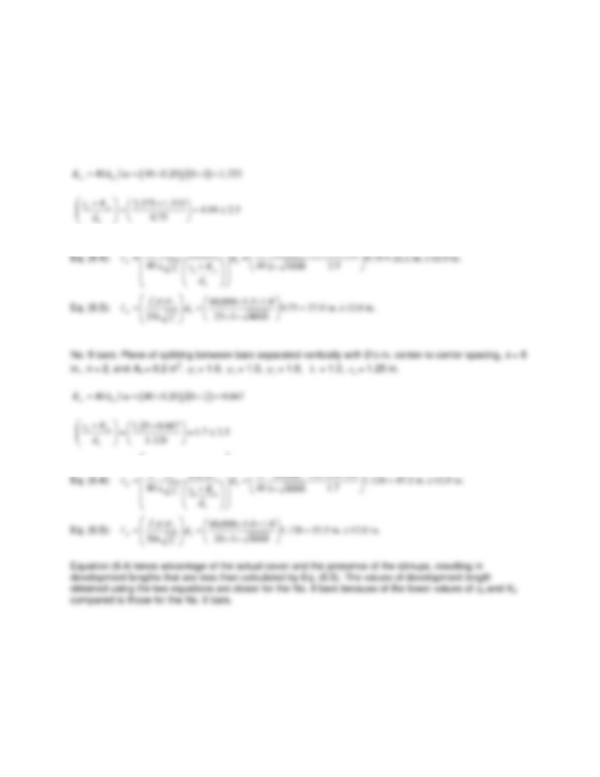
Equation (6.4) takes advantage of the actual cover and the presence of the stirrups, resulting in
development lengths that are less than calculated by Eq. (6.5). The values of development length
obtained using the two equations are closer for the No. 9 bars because of the lower values of cb and Ktr
compared to those for the No. 6 bars.
ψ
ψ
6.5 For the beam cross section shown in Fig. 4.15, what are the development lengths of the top No. 6
bars and bottom No. 9 bars for No. 4 (No. 13) stirrups with
1
½ in. clear side cover spaced at 3 in.
using Eq. (6.4) and (6.5). Normalweight concrete,
c
f′=
4000 psi. Comment.
No. 6 bars: Plane of splitting through side cover, s = 3 in., n = 1, Atr = 0.2 in2.
t
ψ
= 1.3,
e
ψ
= 1.0,
s
ψ
= 0.80,
λ
= 1.0,
b
c
= 2.375 in.
( ) ( )
40 40 0.20 3 1 2.667
tr tr
K A sn= = × ×=
2.375 2.667
6.72 2.5
0.75
b tr
b
cK
d
++
= = ≤
Eq. (6.4):
3 3 60,000 1.3 1.0 0.8 0.75 22.2 in. 12.0 in.
40 40 2.5
λ 1 4000
ytes
db
b tr
c
b
fd
cK
f
d
ψψψ
××
= = = ≥
′+×
Eq. (6.5):
60,000 1.3 1.0 0.75 37.0 in. 12.0 in.
25λ 25 1 4000
yte
db
c
fd
f
ψψ
××
= = = ≥
′××
No. 9 bars: Plane of splitting between bars separated vertically with 2½–in. center–to center spacing, s = 3
t
e
s
ψ
ψ
6.6 For the beam cross section shown in Fig. 4.15, what are the development lengths of the top No. 6
bars and bottom No. 9 bars for No. 4 (No. 13) stirrups with
1
½ in. clear side cover spaced at 6 in.
using Eq. (6.4) and (6.5). Normalweight concrete,
c
f′=
12,000 psi. Comment.
Note that
c
f′
may not exceed 100 psi.
No. 6 bars: Plane of splitting through side cover, s = 6 in., n = 1, Atr = 0.2 in2.
t
ψ
= 1.3,
e
ψ
= 1.0,
s
ψ
= 0.80,
λ
= 1.0,
b
c
= 2.375 in.
( ) ( )
40 40 0.20 6 1 1.333
tr tr
K A sn= = × ×=
2.375 1.333
4.94 2.5
0.75
b tr
b
cK
d
++
= = ≤
Eq. (6.4):
3 3 60,000 1.3 1.0 0.8 0.75 14.0 in. 12.0 in.
40 40 1 100 2.5
λ
ytes
db
b tr
c
b
fd
cK
f
d
ψψψ
××
= = = ≥
×
′+
Eq. (6.5):
60,000 1.3 1.0 0.75 23.4 in. 12.0 in.
25 1 100
25λ
yte
db
c
fd
f
ψψ
××
= = = ≥
××
′
No. 9 bars: Plane of splitting between bars separated vertically with 2½–in. center–to center spacing, s = 6
t
e
ψ
s
ψ
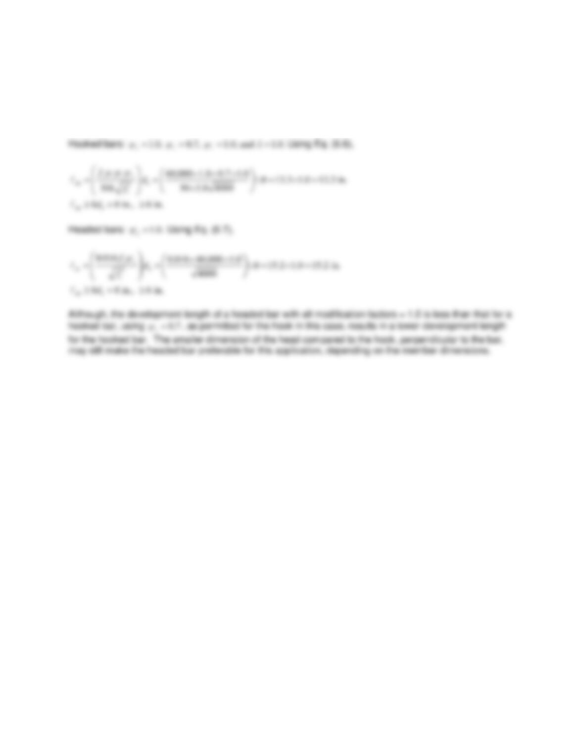
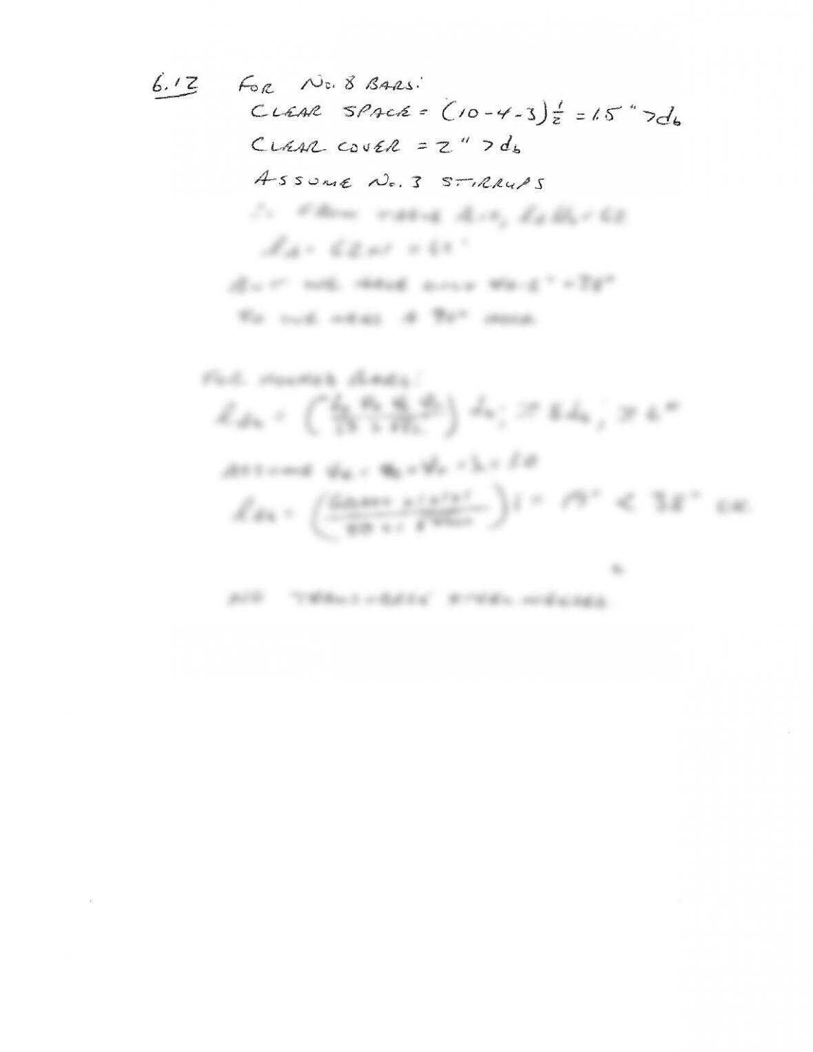
6.7 Compare the development lengths of No. 8 (No. 25) hooked (180° bend) and headed bars cast in a
beam–column joint with 2½ in. clear cover on the bars and 4 in. clear spacing between the bars.
Normalweight concrete,
c
f′
= 4000 psi. Comment.
Assume: fy = 60,000 psi.
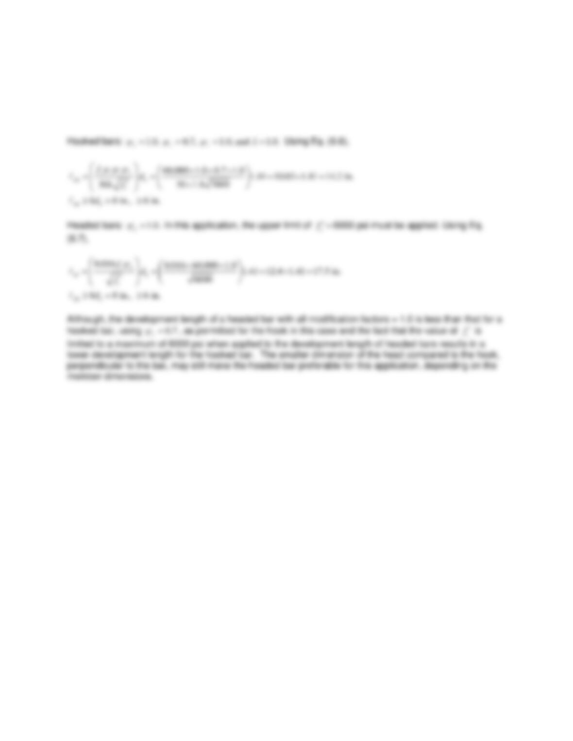
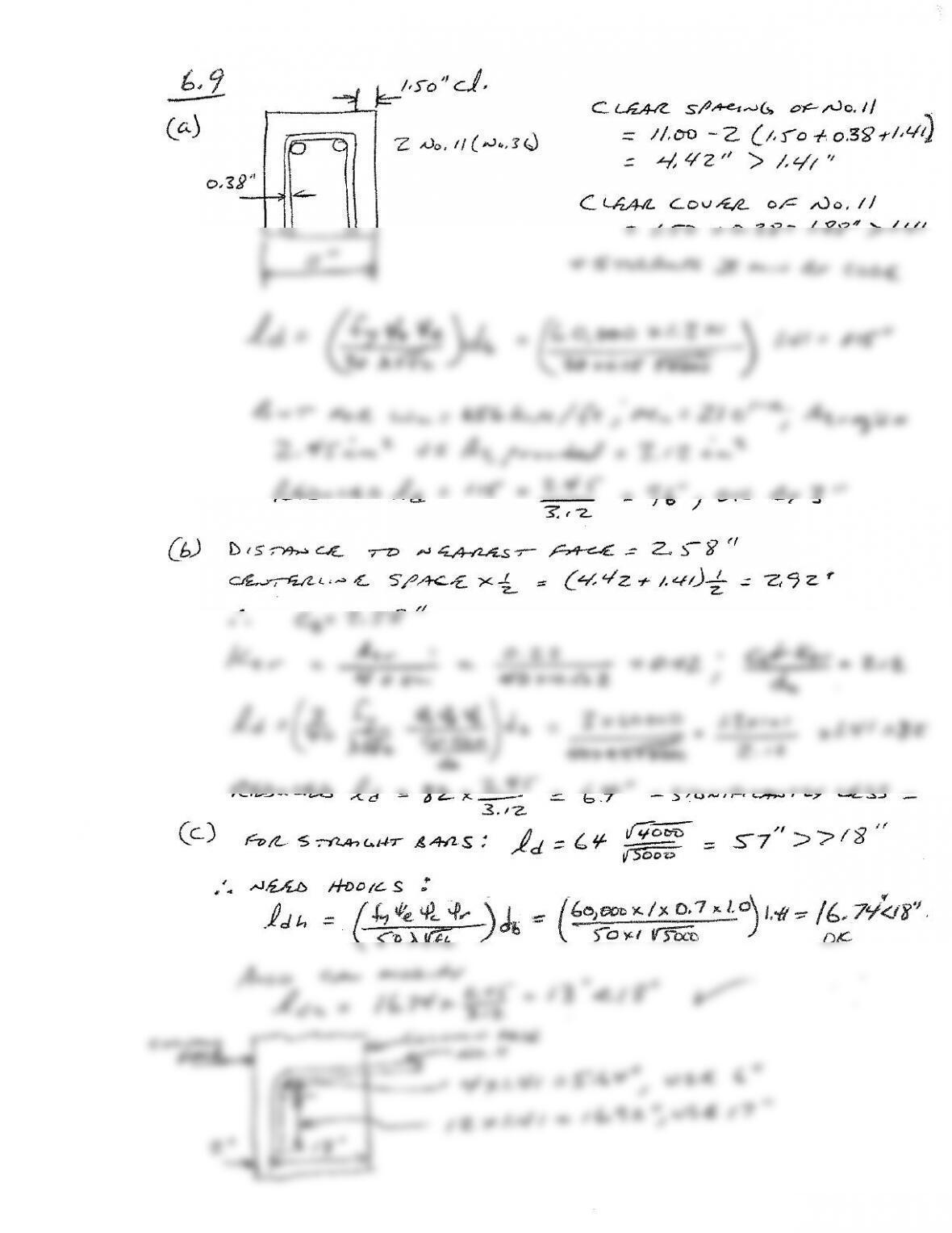
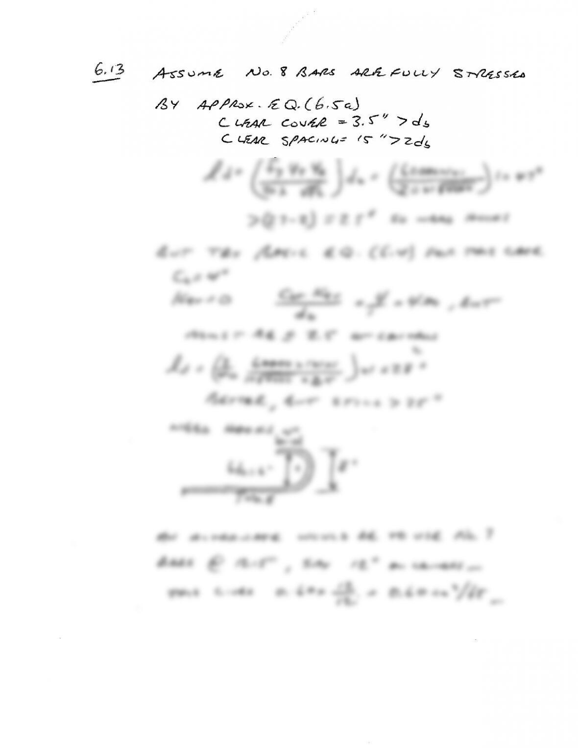
6.8 Compare the development lengths of No. 11 (No. 36) hooked (90° bend) and headed bars cast in a
beam–column joint with 3 in. clear cover on the bars and 6 in. clear spacing between the bars.
Normalweight concrete,
c
f′
= 7000 psi. Comment.
Assume: fy = 60,000 psi.