7.5vf’c.
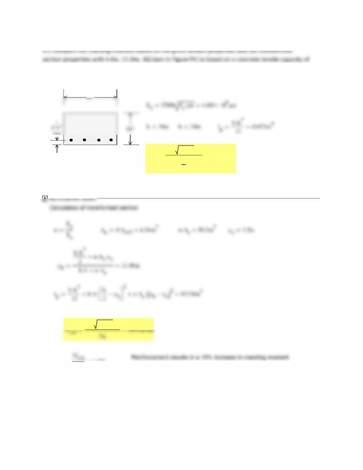
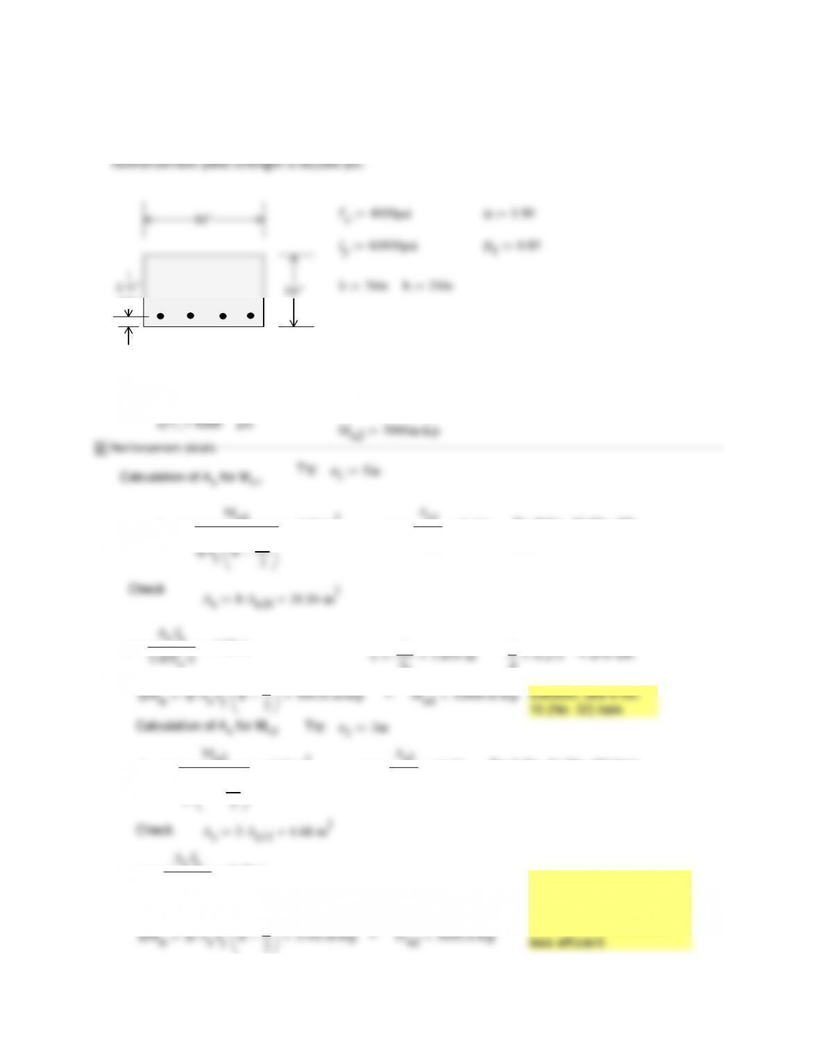
f’c4000psi Es29000000psi
24“
36″
typ
a)f’c=4000psi
12 41472 in4
Mcr
7.5 f’cpsi
Ig
h
2
1639 in kip
Reinforcement results in a 15% increase in cracking moment.
Mcr
1.153
7.5vf’c.
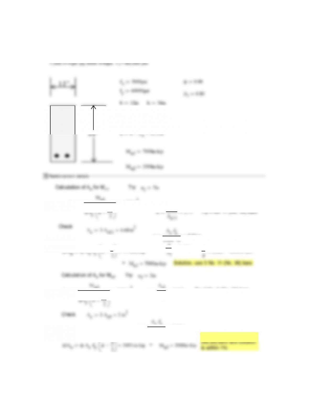
12″ f’c5000psi Ec57000 f’cpsi4.031 106
psi
Es29000000psi
n
Es
Ec
7.2 As2A
s10
2.54 in2
nA
s
18.3 in2
ys2.5in
bh
2
s
ys
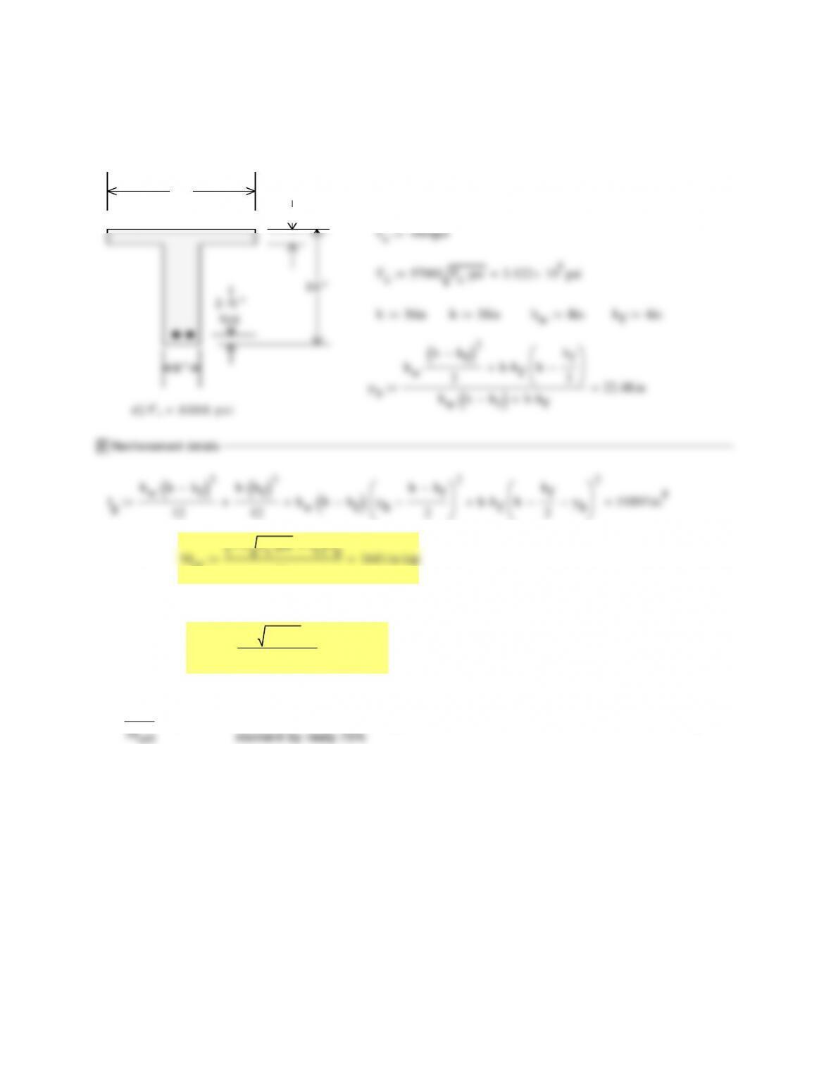
4.3Comparethecrackingmomentbasedonthegrosssectionpropertiesandthetransformed
sectionpropertieswith4‐No.9(No.29)barsinFigureP4.1cbasedonaconcretetensilecapacityof
7.5vf’c.
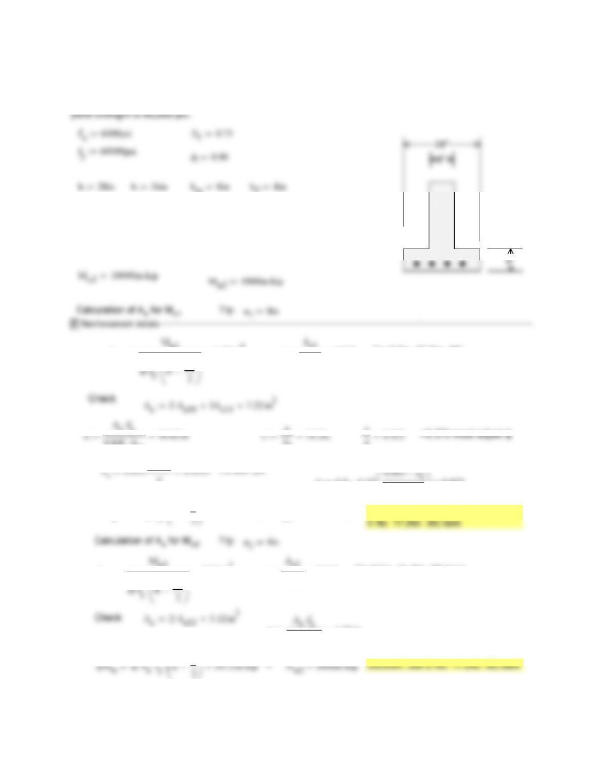
f’c6000psi
28″
8″
Es29000000psi
n
Es
Ec
6.6 As4A
s9
4.00 in2
nA
s
26.3 in2
ys2.5in
yb
b
hf
2
2
bwhh
f
hh
f
2hf
nA
s
ys
bh
f
bwhh
f
nA
s
12.418in
Igc
bh
f
3
12
bwhh
f
3
12
bh
f
yb
hf
2
2
bwhh
f
hh
f
2hf
yb
2
52269 in4
IgIgc nA
s
ybys
2
54853 in4
Ig
Igc
1.049Reinforcement adds 12% to Ig
Reinforcement adds about
10% to the cracking moment
7.5 f’cpsi
Ig
yb
Mcr
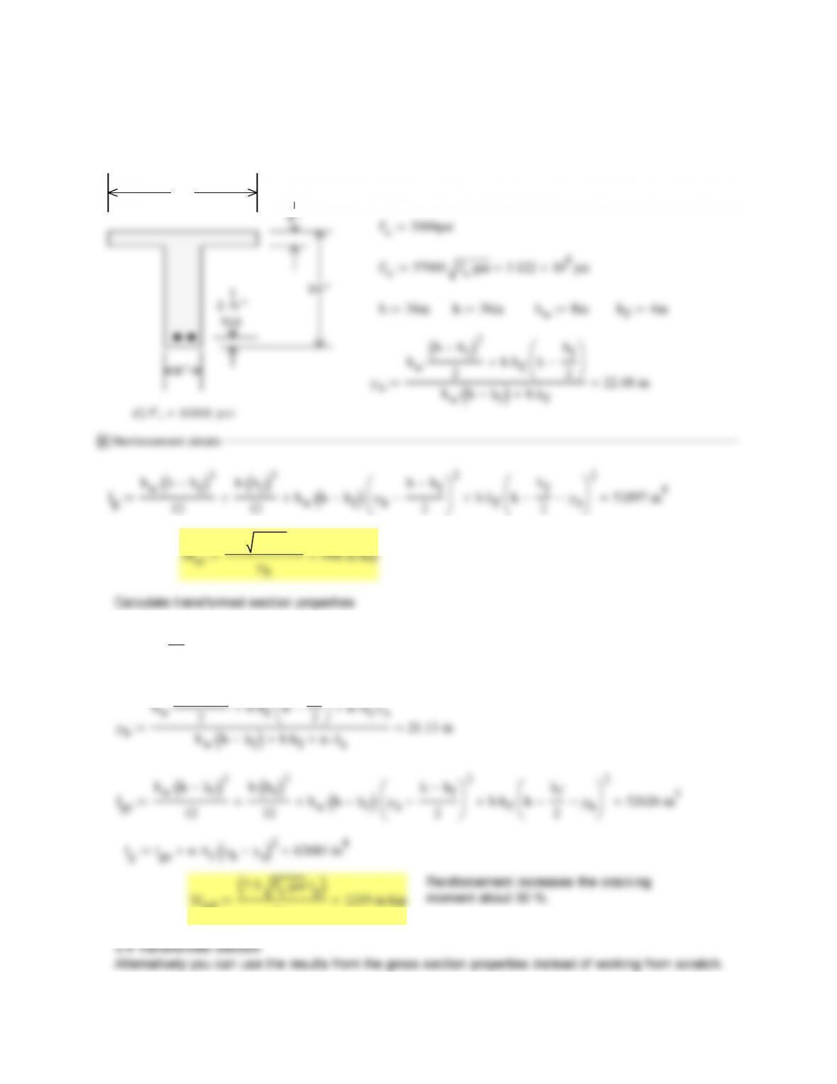
4.4Comparethecrackingmomentbasedonthegrosssectionpropertiesandthetransformed
sectionpropertieswith2‐No.11(No.36)barsinFigureP4.1dbasedonaconcretetensilecapacity
of7.5vf’c.
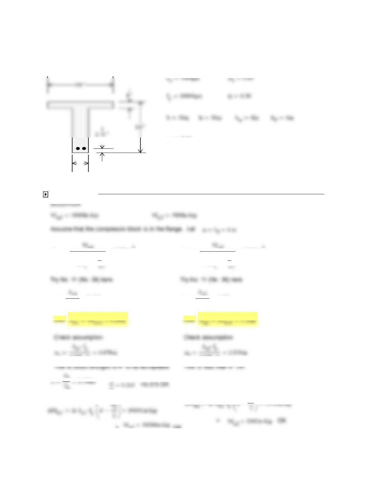
36″
4″
Es29000000psi
n
Es
Ec
9.3 As2A
s11
3.12 in2
nA
s
29 in2
ys2.5in
yb
bw
hh
f
2
2
bh
f
h
hf
2
nA
s
ys
bwhh
f
bh
f
nA
s
21.13 in
Igc
bwhh
f
3
12
bh
f
3
12
bwhh
f
yb
hh
f
2
2
bh
f
h
hf
2
yb
2
52626 in4
IgIgc nA
s
ybys
2
62685 in4
Reinforcement increases the cracking
7.5 f’cpsi
Ig
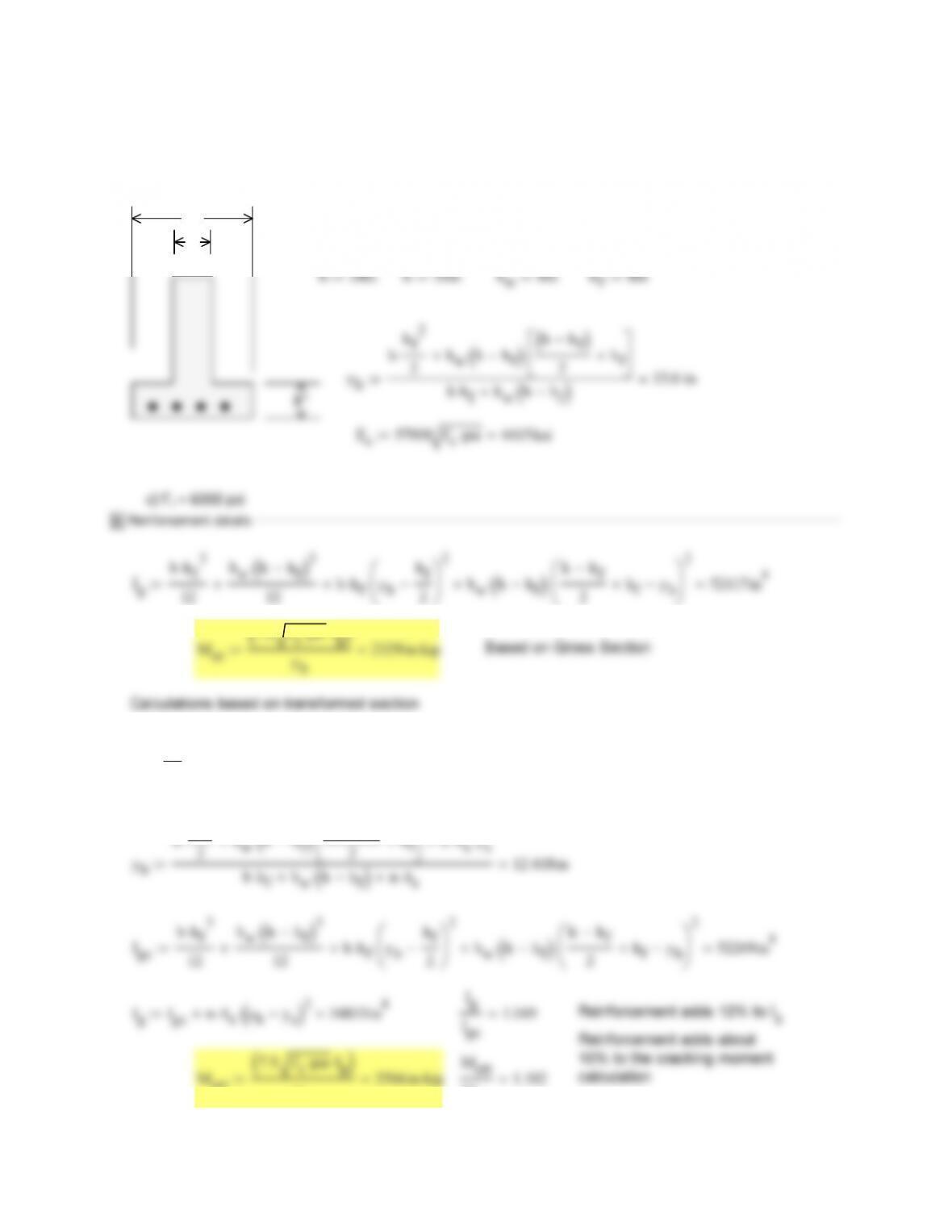
4.5Determinethecrackingmomentbasedonthegross sectionpropertiesinFigureP4.1difthe
sectionisprestressedsuchthatthereisa300psicompressionstressintheextremetensionzone
andtheconcretetensilecapacityis7.5vf’c.
36″
4″
Es29000000psi fc300psi
yb
Mcr0
7.5 f’cpsi
Ig
yb
948 in kip
Mcr
1.73Adding 300 psi prestressing compression to the section increases the cracking
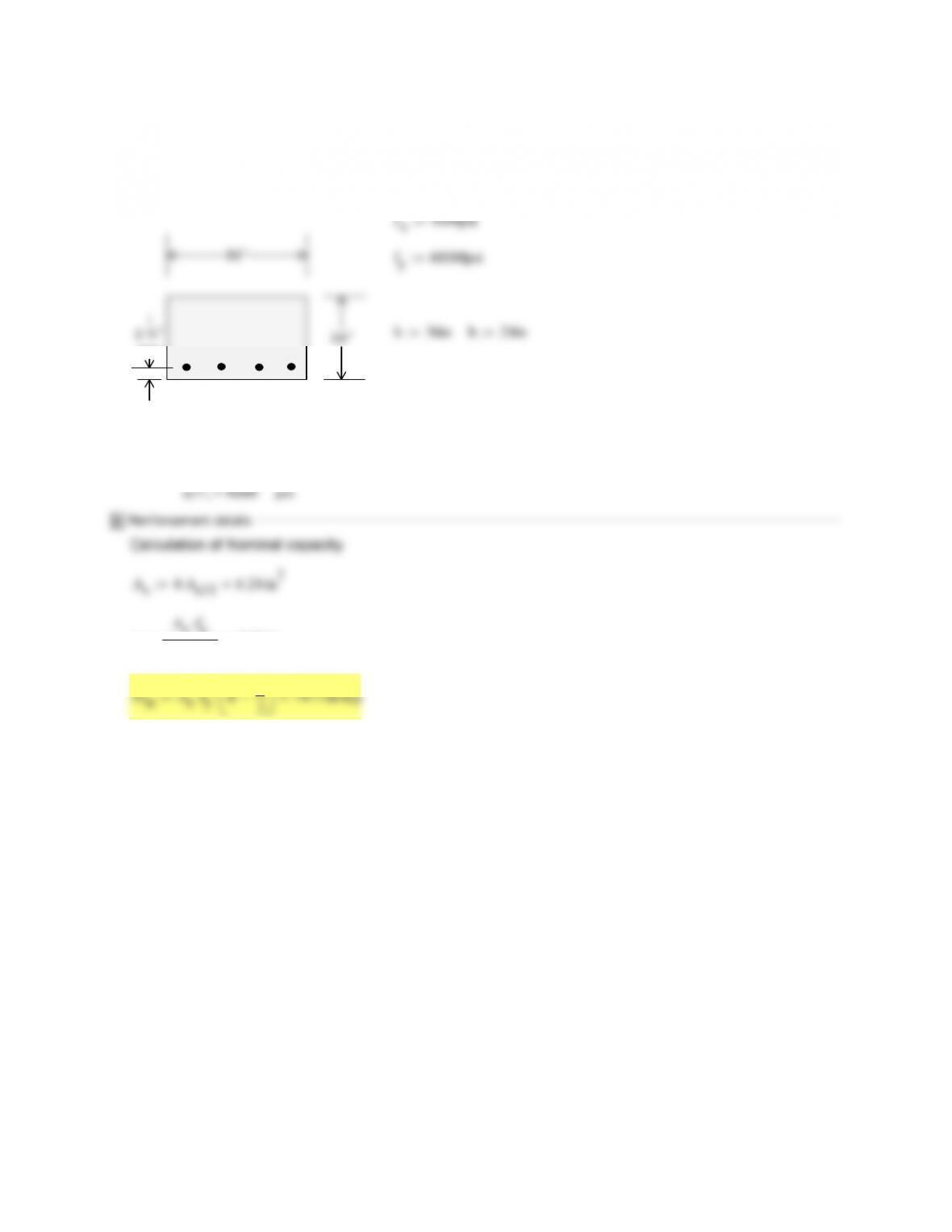
4.6DeterminetheservicelevelmomentcapacityofthesectionsinFigureP4.1iftheallowablestress
forconcreteis0.45f’candtheallowablestressforthereinforcementis30,000psi.Usetheareasof
reinforcementfromProblem4.2.
a)f’c=4000psi
s
fc0.45f’c1800psi fs30000psi
Reinforcement details
Calculation of cracked section
Es
s11
s
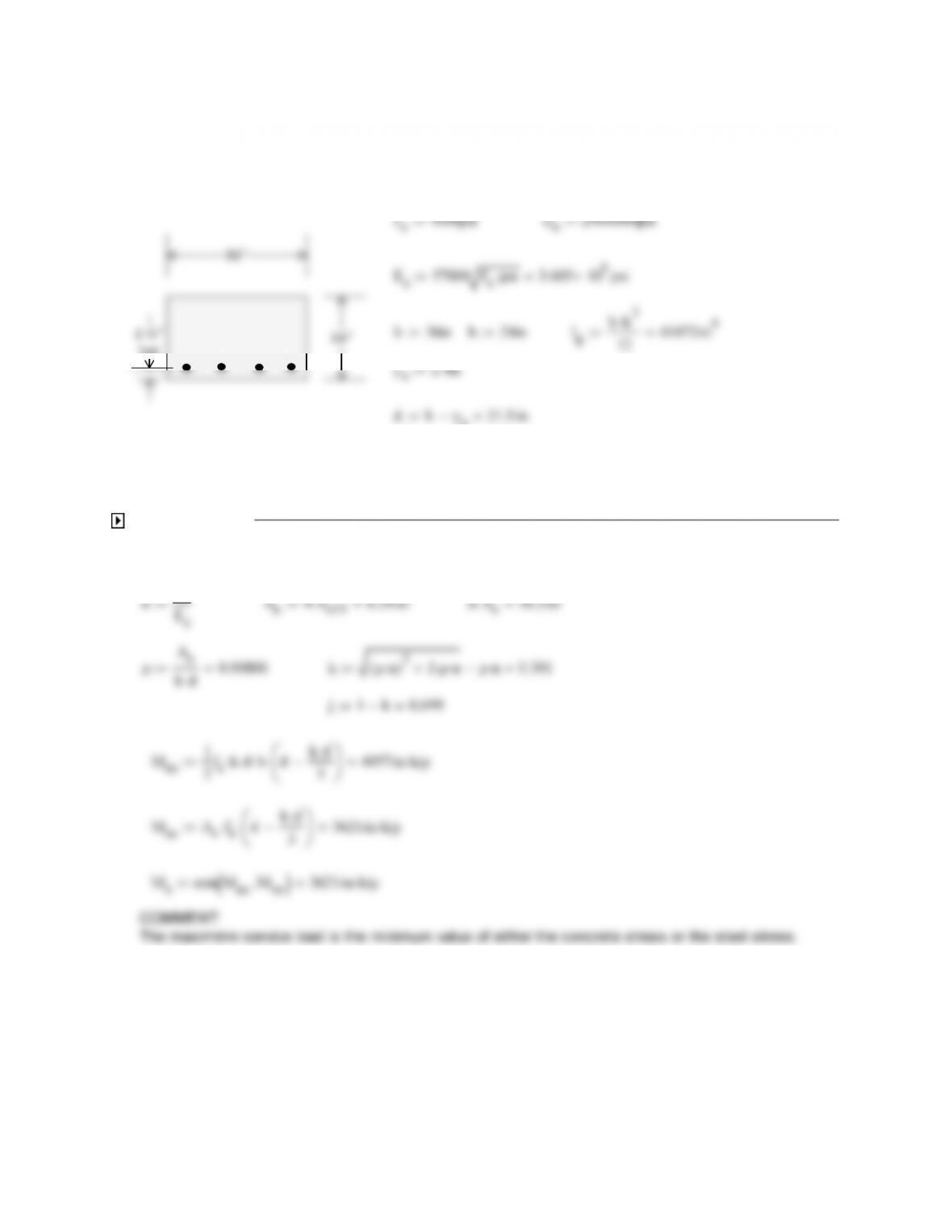
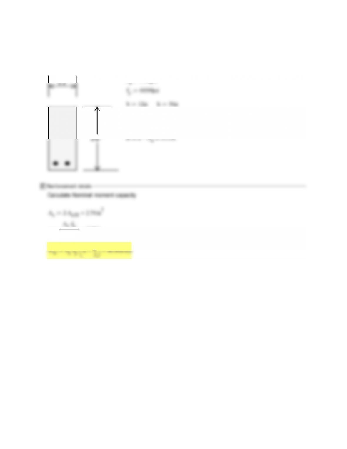
4.7DeterminetheservicelevelmomentcapacityofthesectioninFigureP4.1biftheallowable
stressforconcreteis0.45f’candtheallowablestressforthereinforcementis30,000psi.Usethe
36″
ys2.5in
s
fc0.45f’c2250psi fs30000psi
n
Es
Ec
7.2 As2A
s10
2.54 in2
nA
s
18.3 in2
ys2.5in
ρ
As
bd0.00632 kρn()
22ρn ρn 0.259
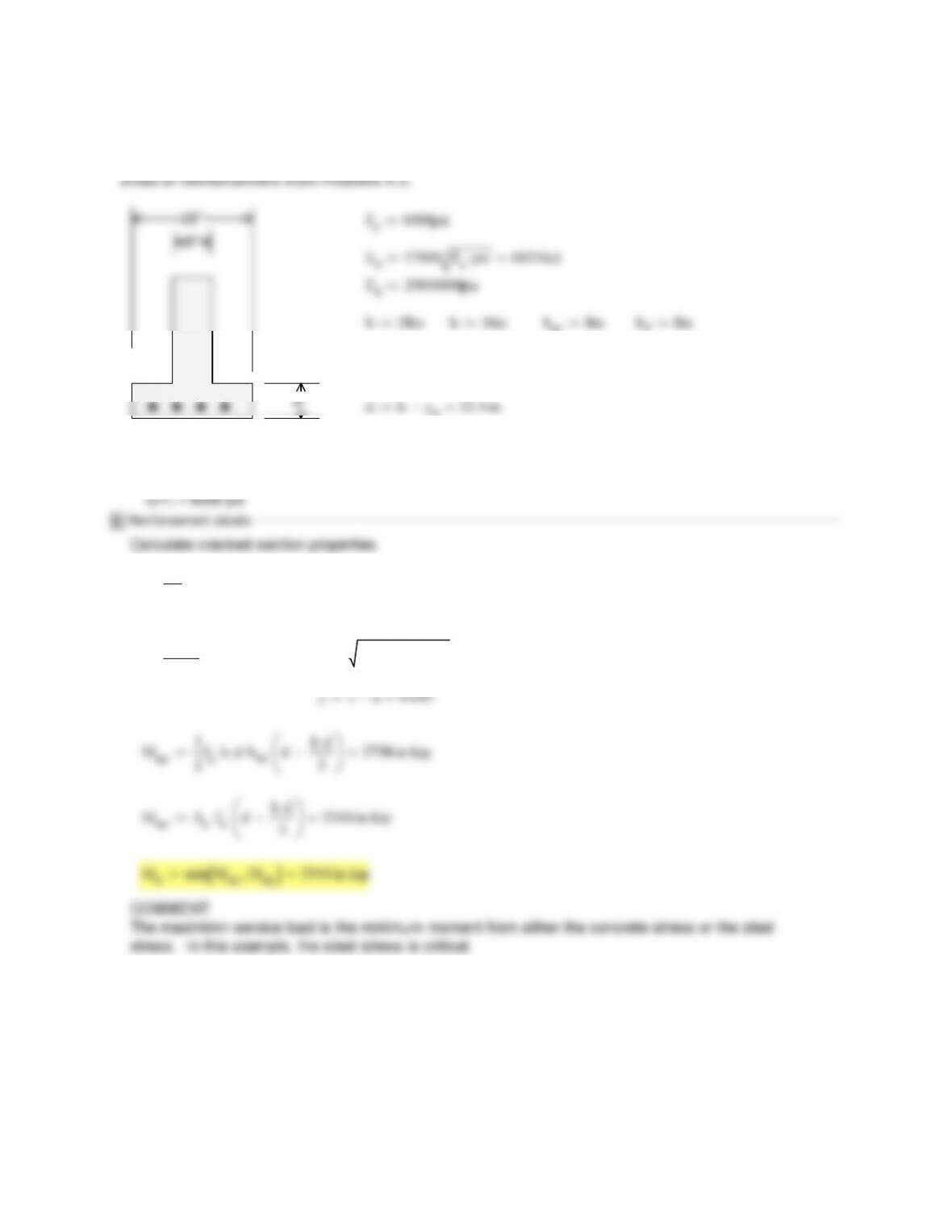
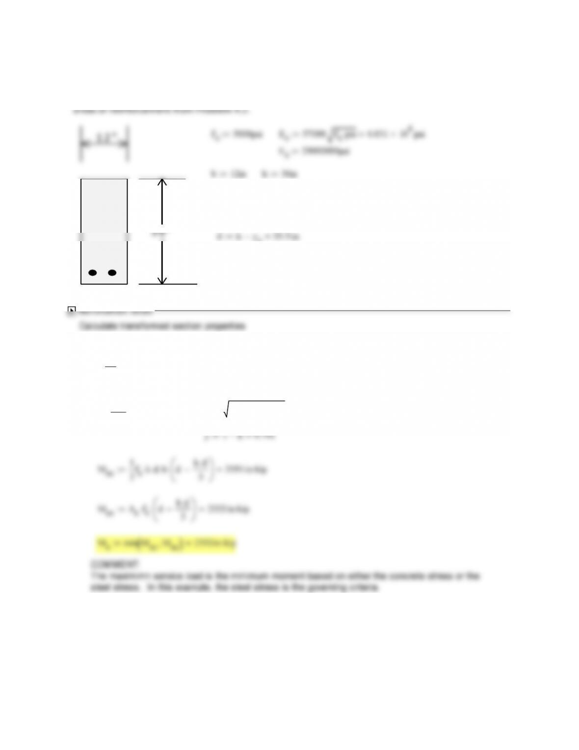
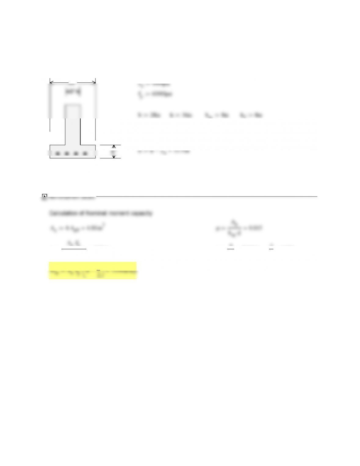
4.8DeterminetheservicelevelmomentcapacityofthesectioninFigureP4.1ciftheallowable
stressforconcreteis0.45f’candtheallowablestressforthereinforcementis30,000psi.Usethe
8″
c)f’c=6000psi
ys2.5in
s
fc0.45f’c2700psi fs30000psi
n
Es
Ec
6.6 As4A
s9
4.00 in2
ρ
As
bwd0.01493 kρn()
22ρn ρn 0.355
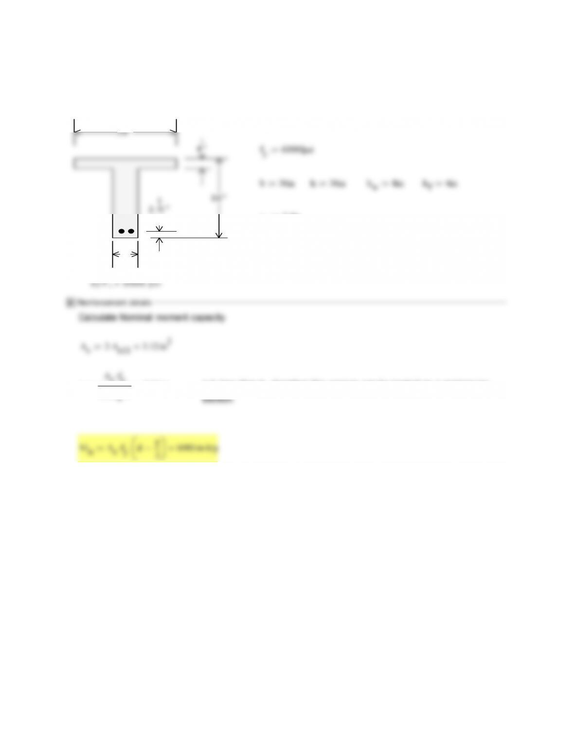
4.9DeterminethenominalmomentcapacityofthesectionsininFig.4.1ausingthe
reinforcementareasfromproblem4.1.Thereinforcementyieldstressis60,000psi.
24“
typ
a)f’c=4000psi
ys2.5in
dhy
s
21.5 in
s11
a
0.85f’cb3.06 in
2
4.10DeterminethenominalmomentcapacityofthesectionsininFig.4.1busingthe
reinforcementareasfromproblem4.2.Thereinforcementyieldstressis60,000psi.
12″ f’c5000psi
fy60000psi
b12in h36in
ys2.5in
s10
a
0.85f’cb2.99 in
2
4.11DeterminethenominalmomentcapacityofthesectionsininFig.4.1cusingthe
reinforcementareasfromproblem4.3.Thereinforcementyieldstressis60,000psi.
c)f’c=6000psi
β10.75
a
0.85f’cbw
5.88 in ca
β1
7.843 in c
d0.234
2
4.12DeterminethenominalmomentcapacityofthesectionsininFig.4.1dusingthe
reinforcementareasfromproblem4.4.Thereinforcementyieldstressis60,000psi.
8″
d)f’c=3000psi
typ
f’c3000psi
ys2.5in
dhy
s
33.5 in
s11
a
0.85f’cb2.04 in a is less than hf, therefore this section can be treated as a rectangular
2
4.13Determinetherequiredareaofreinforcementandthecorrespondingreinforcementratiofor
thesectionsinFigP4.1aiftheultimatemomentisa)10,000in‐kipandb)5,000in‐kip.The
24“
typ
a)f’c=4000psi
ys2.5in
dhy
s
21.5 in
Mu1 10000in kip
s10
β1
d0.273<.375 OK
2
10 (No. 32) bars
Calculation of As for Mn2 Try: a13in
As2
fyd
a1
4.17 in2
n
As11
2.671 Try 3 No. 11 (No. 36) bars
s11
a
0.85f’cb2.29 in Solution, use 3 No. 11 (No.
36) bars
4–No. 10 also is OK but
less efficient
ϕMnϕAs
fy
da
2
5144 in kip >Mu2 5000 in kip
4.14 . Determine the required area of reinforcement and the corresponding reinforcement
ratio for the section in Fig P4.1 b if the ultimate moment is (a)
ys2.5in
ca
0.175m
2
d0.205<0.375 OK
>Mu1 7000in kip Solution, use 3 No. 11 (No. 36) bars
Calculation of As for Mn2 Try: a13in
2
s9
2
a
0.85f’cb2.35 in
Solution, use 2 No. 9
is within 1%
2
4.15Determinetherequiredareaofreinforcementandthecorrespondingreinforcementratioforthe
sectionsinFigP4.1ciftheultimatemomentisa)10,000in‐kip,b)5,000in‐kip.Thereinforcement
8″
ys2.5in
β10.75
dhy
s
33.5 in
2
0.85f’cbw
10.62 in ca
β1
d0.423>0.375 must adjust ϕ
c
ϕ0.9 0.25
0.003
0.825
ϕMnϕAs
fy
da
10074 in kip >Mu1 10000in kip Solution, use 2 No. 10 (No. 32) plus
2
a
0.85f’cb1.31 in
4.16. Determine the required area of reinforcement and the corresponding reinforcement ratio for the
section in Fig P4.1 d if the ultimate moment is (a) 10,000 in–kips and (b) 5000 in-kips. f y = 60,000
psi. Comment on your solutions.
8″
d)f’c=3000psi
typ
ys2.5in
dhy
s
33.5 in
Reinforcement details
As1
ϕfy
da
5.879 in2
As2
ϕfy
da
2.939 in2
n1
As11
3.769 n2
As11
1.884
a1
0.85f’cb4.078 in a2
0.85f’cb2.039 in
β1
d0.143<0.375 OK
a2
2
ϕMn1 ϕAs1
fy
d
2
10601 in kip
>Mu2 5000in kip OK
Mu1 10000in kip
>OK
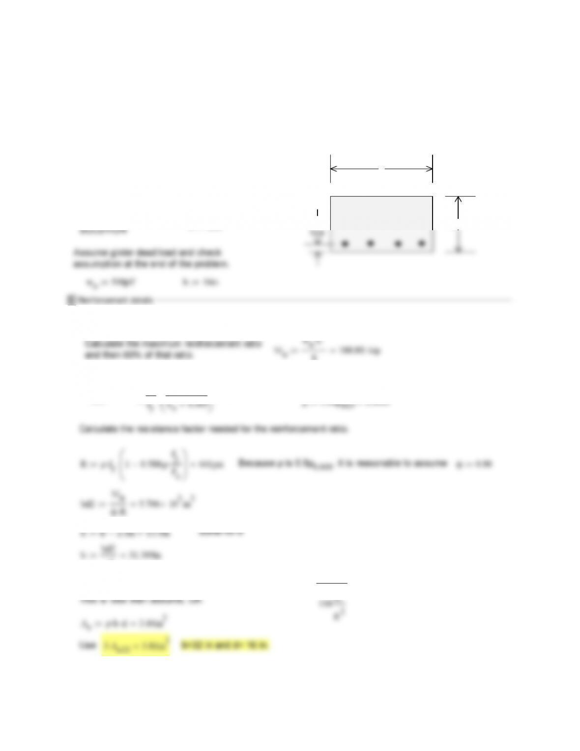
Problem 4.17 A rectangular beam made using concrete with f’c = 6000 psi and steel with fy = 60,000 psi
had a width b = 20 in., and an effective depth of d = 17.5 in and an h =20 in. The Concrete modulus of
rupture fr = 530 psi. The elastic modulus of the steel and concrete are, respectively Ec = 4,030,000 psi
and Es = 29,000,000 psi. The area of steel is four No. 11(No. 36) bars.
fr7.5 f’cpsi fr581 psin
Es
Ec
n 6.6
(a) Find the maximum service load that can be resisted without stressing the concrete
fc0.45f’c
fc2700 psi
fs0.60fy
fs36000 psi
ρ
As
bd
ρ0.018
kρn()
22ρn ρn k 0.381
k
Msmin Mss Msc
Ms229 ft kip
(b) Determine if the beam will show cracking before reaching the service load
Ig
bh
3
Ig13333 in4
frIg
nA
s
dh
s
Iut Igbd∆y2
nA
s
dh
2
∆y
2
Iut 15400 in4
frIut
0.85f’cb
MnAsfy
da
2
Mn489 ft kip
(d) Compute the ratio of the nominal capacity of the beam to the maximum service level capacity and
4.18. A rectangular, tension–reinforced beam is to be designed for dead load of 500 lb/ft plus
self-weight and service live load of 1200 lb/ft, with a 22 ft simple span. Material strengths will be fy =
60 ksi and fc
・
= 3 ksi for steel and concrete, respectively. The total beam depth must not exceed 16
in. Calculate the required beam width and tensile steel requirement, using a reinforcement
ratio of 0.60
ρ
0.005 . Use ACI load factors and strength reduction factors. The
effective depth may be assumed to be 2.5 in. less than the total depth.
16″
b
2‐½”
wd500plf f’c3000psi β10.85
εu0.003
wl1200plf fy60000psi
L22ft
wu1.2 wdwo
1.6 wl
3120plf
Calculate the maximum reinforcement ratio
and then 60% of that ratio. Mu
wuL2
8188.8ft kip
ρ005 0.85β1
f’c
εu
0.014 ρ0.60ρ005 0.0081
Rρfy
1 0.588 ρfy
f’c
441psi Because ρ is 0.6ρ0.005, it is reasonable to assume ϕ0.90
d231.309in
Use b = 32 in. and then check assumptions. wo
150 pcf
bd440.3plf
s10
Problem 4.19 A rectangular reinforced concrete section has dimension b=14 in., d=25 in, and h =
28 in., and is reinforced with 3 No. 10 (No. 32) bars. The material strengths are f’c = 5000 psi, fy =
60,000 psi.
(a) Find the moment that will produce first cracking at the bottom surface of the section
fr7.5 f’cpsi fr530 psin
Es
Ec
n 7.2
(a) Find the moment that will produce first cracking at the bottom surface of the section
basing your calculations on Ig, the moment of inertial of the gross section.
bh
3
frIg
Mcr2
h
2∆y
Mcr2 95.5 ft kip Mcr2
Mcr1
1.181
0.45 f’c or the steel stress exceeding 0.60 fy.