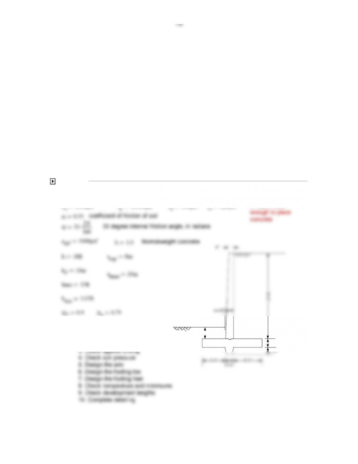
16.1. A cantilever retaining wall is to be designed with geometry as indicated in Fig. P16.1 .
Backfill material will be well–drained gravel having unit weight w = 120 pcf, internal friction angle
ϕ
‘
= 33 , and friction factor against the concrete base f = 0.55. Backfill placed in front of the
toe will have the same properties and will be well compacted. The final grade behind the wall
will be level with the top of the wall, with no surcharge. At the lower level, it will be 3 ft above
the top of the base slab. To improve sliding resistance, a key will be used, tentatively
projecting to a depth 4 ft below the top of the base slab. (This dimension may be modified if
necessary.)
(a) Based on a stability investigation, select wall geometry suitable for the specified
conditions. For a first trial, place the outer face of the wall 1 _ 3 the width of the base slab back
from the toe.
(b) Prepare the complete structural design, specifying size, placement, and cutoff points for all
reinforcement. Materials have strengths fc = 4000 psi and f y = 60,000 psi. Allowable soil
bearing pressure is 5000 psf.
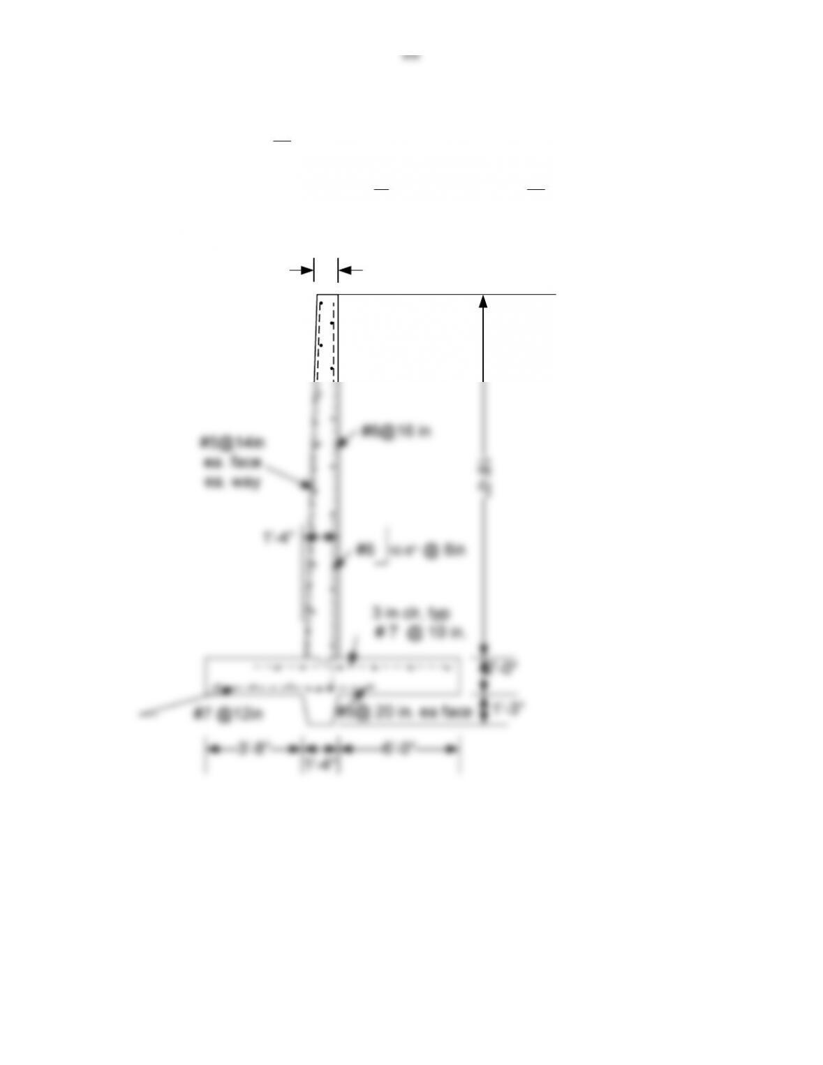
Reinforcement
NOTES
Given Material Properties and trial dimensions
f’c4000psi fy60000psi γc150pcf γs120pcf 8” top is wide
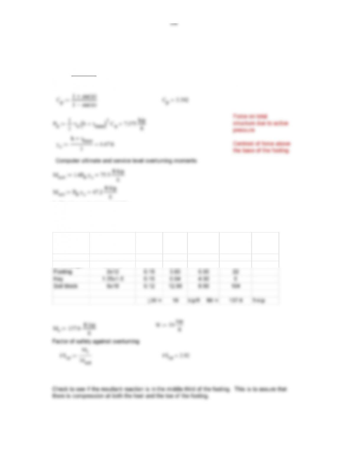
1. Compute overturning forces
Ca
1 sin ϕ()
1 sin ϕ()
Ca0.295
1 sin ϕ()
ft
2. Check overturning stability
Compute the resisting moment of lifting the wall and the soil block about the
toe of the footing ignoring the soil over the toe. Calculations are from an
EXCEL spreadsheet for a one foot length..
Component Dimensions
Unit
weight
(kcf) Weight
Moment
arm (ft) Mr (ft-kip/ft)
Arm rectangle 8/12x18 0.15 1.80 4.68 8
Arm triangle 8/12*18 0.15 0.90 4.12 4
3. Check factor of safety against sliding
The resistance against sliding is
RsμW Rs10.45 kip
ft
Rs
Ph
4. Check soil pressure under the footing
The area and the section modulus of one foot width of the footing are
A base Sbase2
6
so the design is OK. The heel
pressure is near zero, meaning it
may be close to uplift if the full
active pressure occurs.
qtoe
A
S
qtoe 2567 psf
W
A
2ecc
S
5. Design retaining wall arm
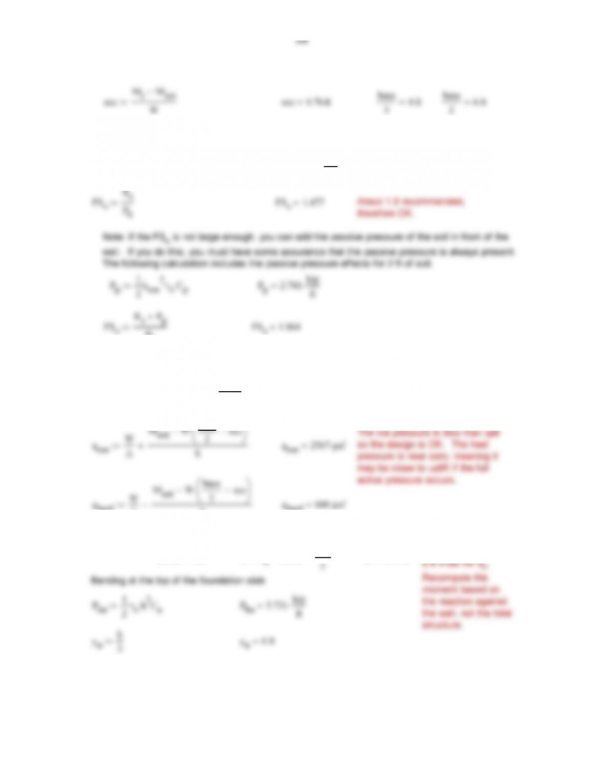
For the first try, use
cover 3in dh
d 12.4 in
3
4/8
ft
Now check the moment capacity 9‘ down from the top of the wall.
This requires computing the structural depth 9 ft down and the moment at that location.
h19ft
9
5/8
Check a
As1
Mu1
ϕffy
d1
a
2
As1 0.247 in2
ft
a
As1 fy
0.85f’c12in
ft
a 0.363 in
Try #6 at 16 in on center a<a assumed, therefore OK.
s<18″ or 5d-OK
12 in
required, therefore only have to
Mn1 ϕfAs1
fy
d1
Mn1 18.5 ft kip
ft
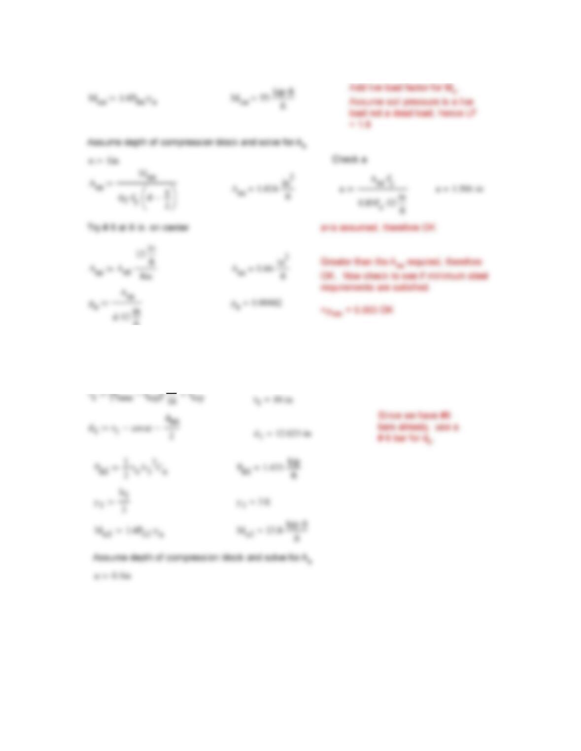
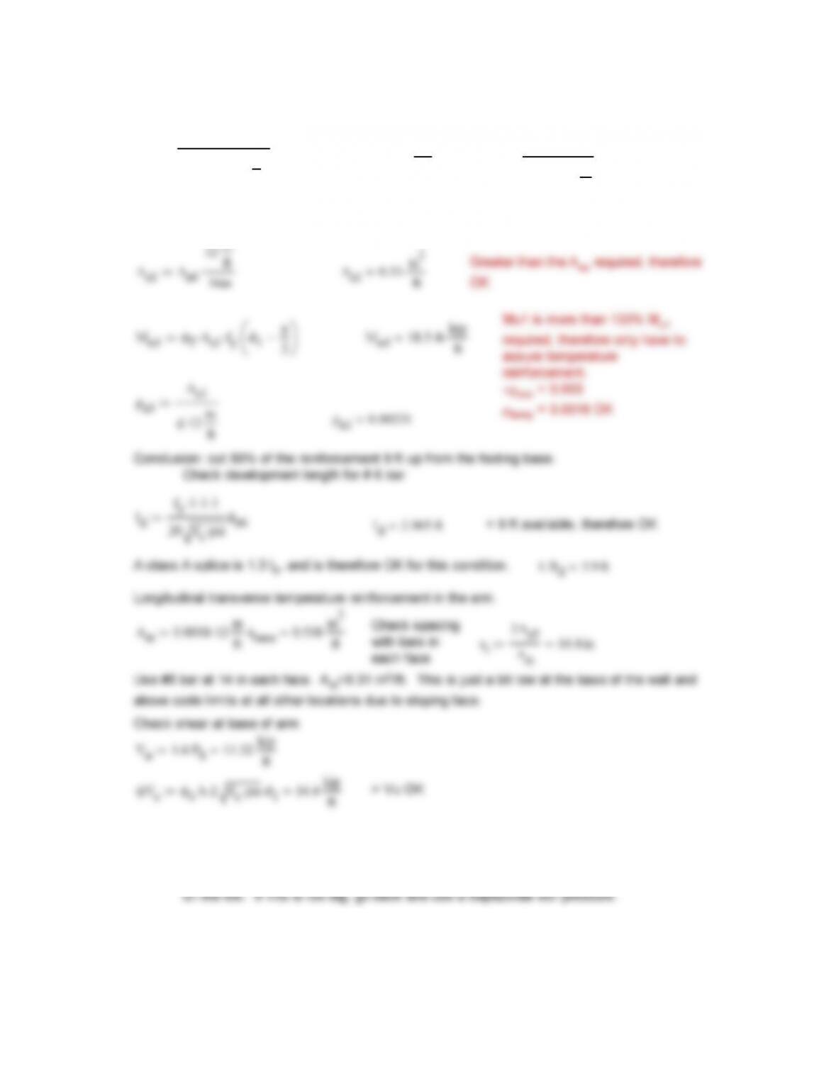
6. Design Toe
The toe extends 4 feet from the face of the wall. Assume a constant soil pressure
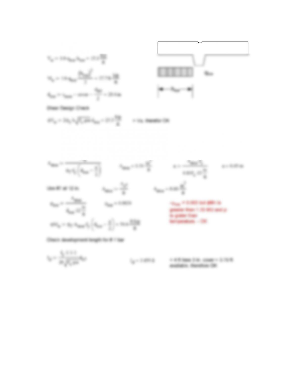
6/8
Compute Loads
ft
Moment Design
Assume depth of compression block and solve for As
a1in Check a
Mu
a
a
Astoe fy
a 0.45 in
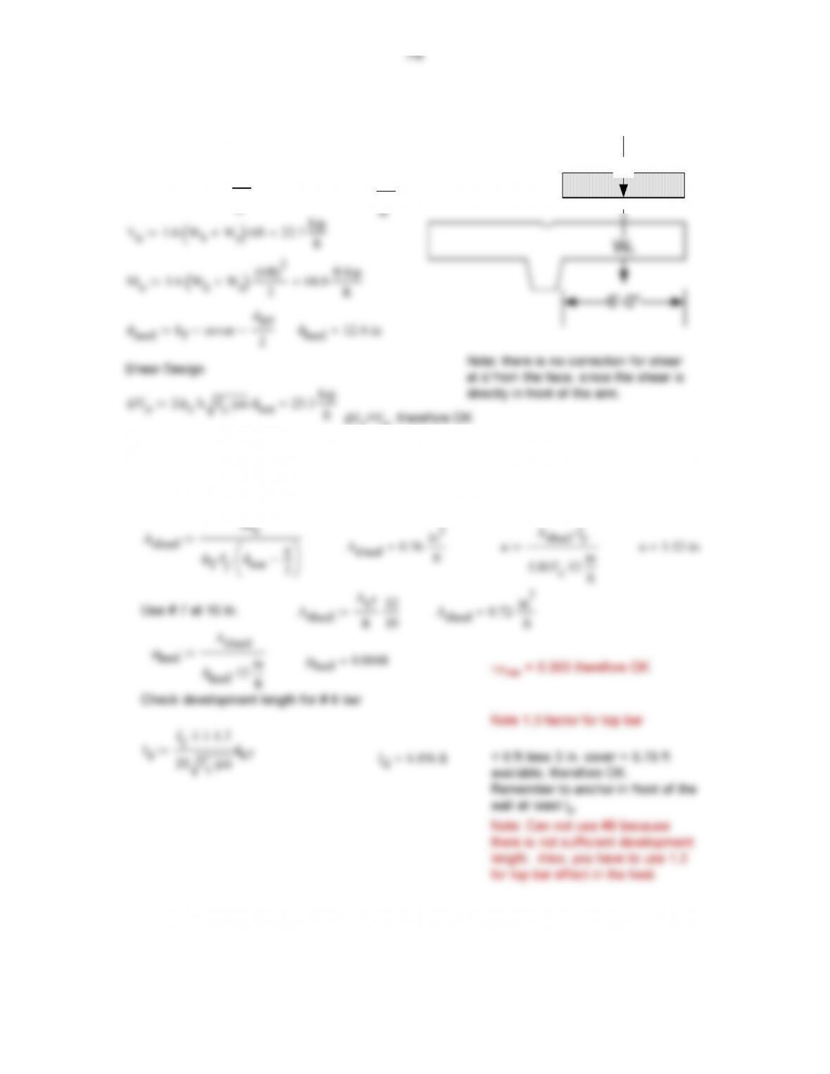
Ws
7. Design heel
The heel must lift itself plus the soil block above
Compute Loads
Whhfγc
0.2 kip
Wshγs
2.16 kip
Moment Design
Assume depth of compression block and solve for As
a 1.2in Check a
Mu
Asheel fy
Base Temperature reinforcement
Ast 0.0018 hf
0.346 in2
ft
Use # 5 at 10 in. spacing = 20” on top and bottom
Ast As5
12
10
Ast 0.372 ft in2
ft
8″
#5@14in
#6@16 in
#6 10-8″” @ 8in
3 in clr, typ
# 7 @ 10 in.
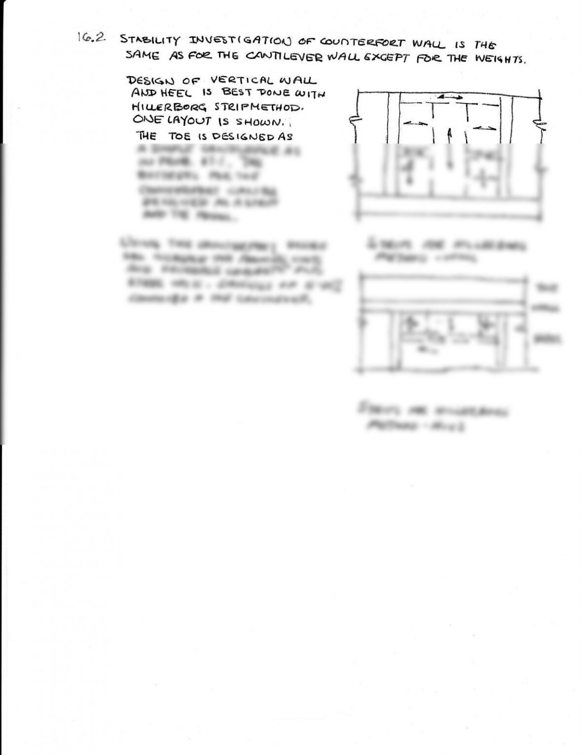
1C.2 Srrr,rurr[
SfiHE AS
INV€trr(C,jT(ot.J oF c4,ut*\T€Efr4T Wf+tt- rs 16{6
Fe rilE C,(l^JTtLE\/E:e dAU- cxcgPr F6e. TH€ yVE-tqH7s.
‘D€E((}u a? V€e*r t cffL (,\, All-
At”tr) t{€-EL ts BeST npofr.re Arr-T*
t (r(LeRl3oe€ sTet l=HqrHoD.
Ohlg tr+YOLrf lS sF{o{^r,V, ,
1′{E TOC tS P6SI6.UED AS
STA,fs’ d{r€ H t Lt-r:e.Eq€q,
fl&-Twop – Hee t