1778 Solutions Manual
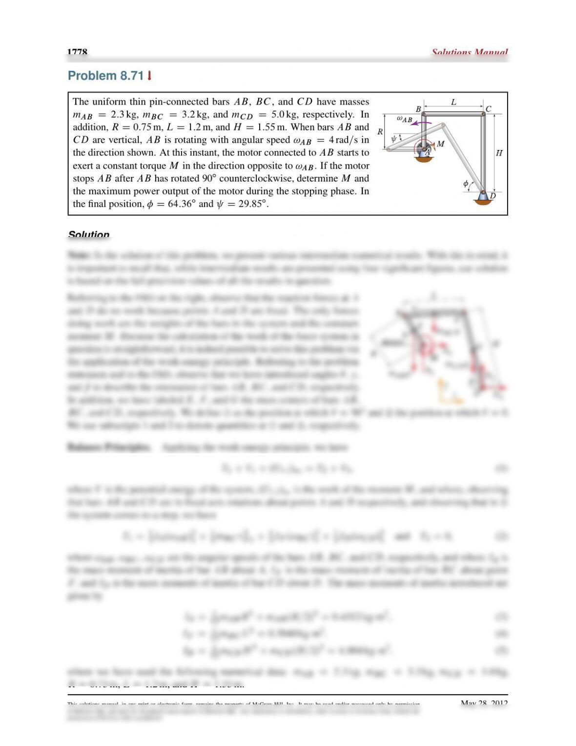
The uniform thin pin-connected bars
AB
,
BC
, and
CD
have masses
mAB D2:3 kg
,
mBC D3:2 kg
, and
mCD D5:0 kg
, respectively. In
addition,
RD0:75
m,
LD1:2
m, and
HD1:55
m. When bars
AB
and
CD
are vertical,
AB
is rotating with angular speed
!AB D4rad=s
in
the direction shown. At this instant, the motor connected to
AB
starts to
exert a constant torque
M
in the direction opposite to
!AB
. If the motor
stops
AB
after
AB
has rotated
90ı
counterclockwise, determine
M
and
the maximum power output of the motor during the stopping phase. In
the final position, D64:36ıand D29:85ı.
Solution
Note:
In the solution of this problem, we present various intermediate numerical results. With this in mind, it
Dynamics 2e 1779
Force Laws. Using the datum shown, we have
of McGraw-Hill, and must be surrendered upon request of McGraw-Hill. Any duplication or distribution, either in print or electronic form, without the
permission of McGraw-Hill, is prohibited.
1780 Solutions Manual
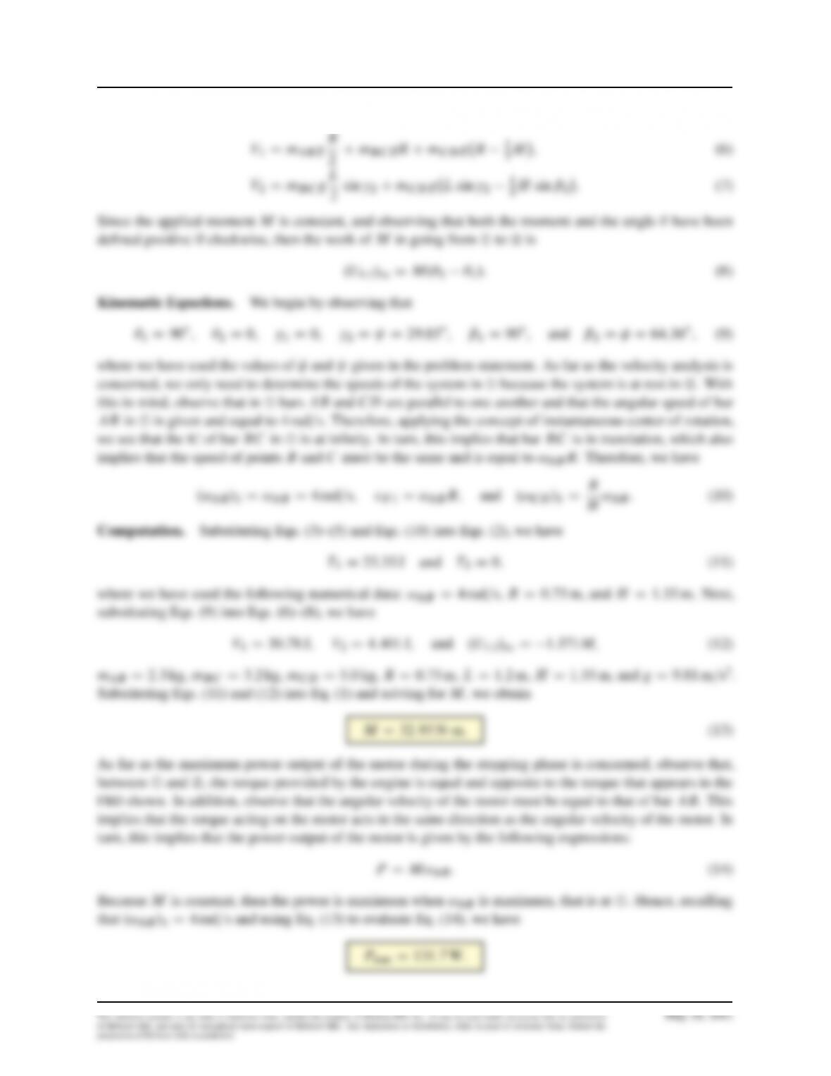
A stick of length
L
and mass
m
is in equilibrium while standing on its end
A
when
end
B
is gently nudged to the right, causing the stick to fall. Letting the coefficient
of static friction between the stick and the ground be
sD0:7
and modeling
the stick as a uniform slender bar, find the value of
✓
at which end
A
of the stick
starts slipping, and determine the corresponding direction of slip. As part of the
solution, plot the absolute value of the ratio between the friction and normal force
as a function of ✓. To solve this problem, follow the steps below.
(a) Letting Fand Nbe the friction and normal forces, respectively, between the
stick and the ground, draw the
FBD
of the stick as it falls. Then set the sum
of forces in the horizontal and vertical directions equal to the corresponding
components of
mEaG
. Express the components of
EaG
in terms of
✓
,
P
✓
, and
R
✓
.
Finally, express Fand Nas functions of ✓,P
✓, and R
✓.
(b)
Use the work-energy principle to find an expression for
P
✓2.✓/
. Differentiate
the expression for
P
✓2.✓/
with respect to time, and find an expression for
R
✓.✓/
.
(c)
After substituting the expressions for
P
✓2.✓/
and
R
✓.✓/
into
the expressions for
F
and
N
, plot
jF=N j
as a function
of
✓
. For impending slip,
jF=N j
must be equal to
s
.
Therefore, the desired value of
✓
corresponds to the intersection of
the plot of jF=N jwith the horizontal line intercepting the vertical axis at the
value 0.7. After determining the desired value of
✓
, the direction of slip can
be found by determining the sign of Fevaluated at the ✓computed.
Solution
For the sake of a more compact presentation, in the solution to this
problem, we will follow the steps indicated in the problem statement
Dynamics 2e 1781
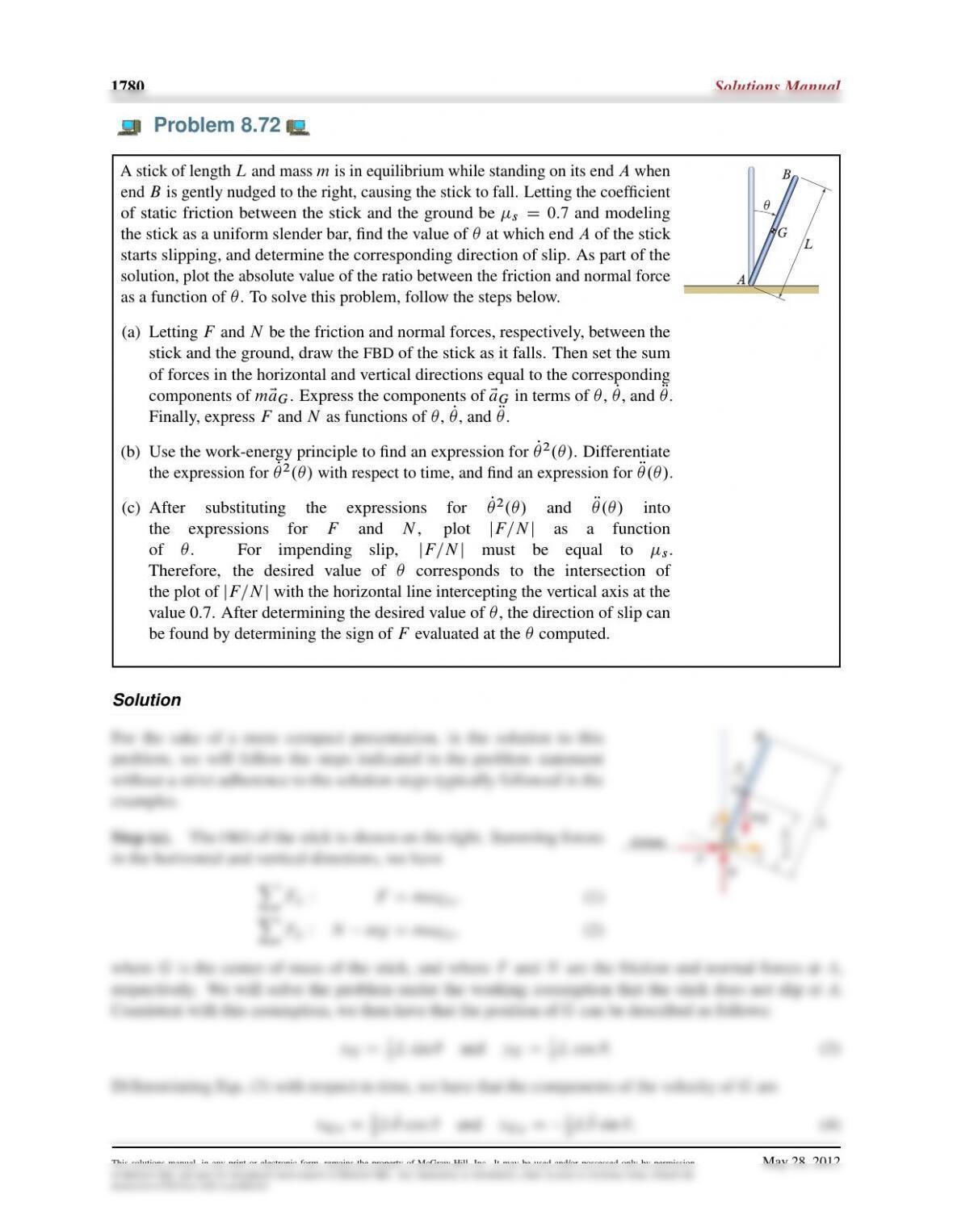
Differentiating Eqs. (4) with respect to time, we have that the components of the acceleration of Gare
2mL. R
2g .R
Step (b).
We begin by defining
¿
to the the position of the stick at release and
¡
the position of the stick at
a generic angle
✓
following
¿
. We observe that, as long as
A
does not slip, friction does no work and the
system can be treated as being conservative. Hence, we can apply the work-energy principle as follows:
2◆2
where we have made use of the parallel axis theorem. Next, substituting Eq. (8) into Eq. (7) and solving for
Step (c).
Substituting the expressions for
P
✓2
and
R
✓
given in Eqs. (10) and (11) into the expressions for
F
and Nin Eqs. (6), after simplification gives
of McGraw-Hill, and must be surrendered upon request of McGraw-Hill. Any duplication or distribution, either in print or electronic form, without the
permission of McGraw-Hill, is prohibited.
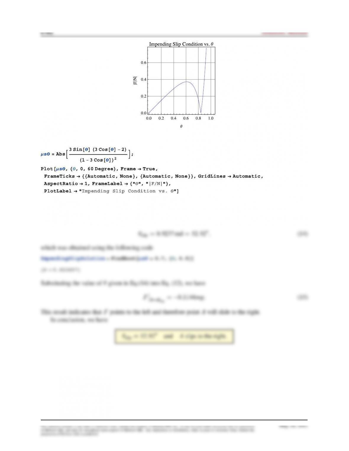
The above plot was obtained using the following Mathematica code:
From the above plot, we see that the function
jF=N j
achieves the value
sD0:7
, near
✓D0:9 rad
. Hence,
we will find the numerical solution to our problem by providing the value
0:9
as the initial guess for
✓
. By
doing so, we obtain the following solution
of McGraw-Hill, and must be surrendered upon request of McGraw-Hill. Any duplication or distribution, either in print or electronic form, without the
permission of McGraw-Hill, is prohibited.
Dynamics 2e 1783
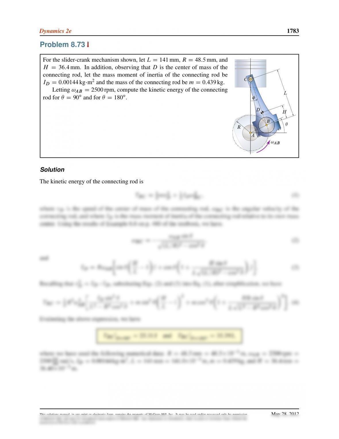
Problem 8.73
For the slider-crank mechanism shown, let
LD141 mm
,
RD48:5 mm
, and
HD36:4 mm
. In addition, observing that
D
is the center of mass of the
connecting rod, let the mass moment of inertia of the connecting rod be
IDD0:00144 kgm2and the mass of the connecting rod be mD0:439 kg.
Letting
!AB D2500 rpm
, compute the kinetic energy of the connecting
rod for ✓D90ıand for ✓D180ı.
Solution
The kinetic energy of the connecting rod is
TBC D1
2mv2
DC1
2ID!2
BC ;(1)
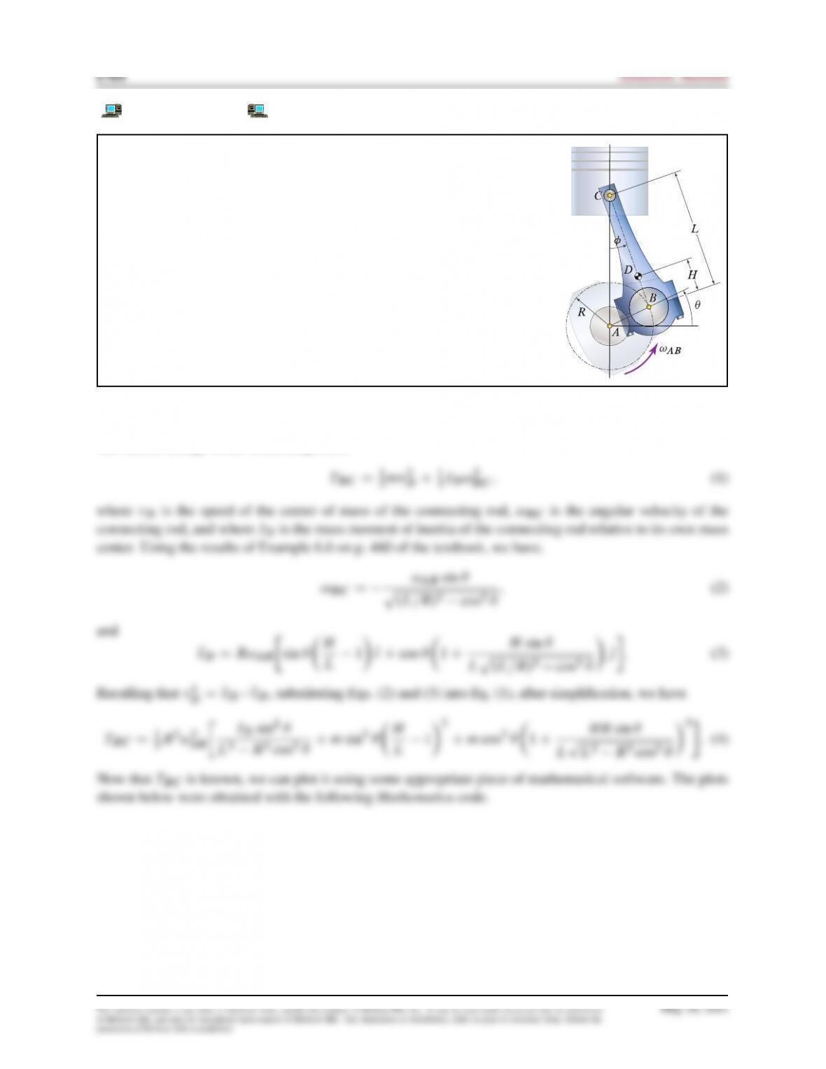
Problem 8.74
For the slider-crank mechanism shown, let
LD141 mm
,
RD48:5 mm
, and
HD36:4 mm
. In addition, observing that
D
is the center of mass of the
connecting rod, let the mass moment of inertia of the connecting rod be
IDD0:00144 kgm2and the mass of the connecting rod be mD0:439 kg.
Plot the kinetic energy of the connecting rod as a function of the crank
angle
✓
over one full cycle of the crank for
!AB D2500 rpm
,
5000 rpm
, and
7500 rpm.
Solution
The kinetic energy of the connecting rod is
of McGraw-Hill, and must be surrendered upon request of McGraw-Hill. Any duplication or distribution, either in print or electronic form, without the
permission of McGraw-Hill, is prohibited.

of McGraw-Hill, and must be surrendered upon request of McGraw-Hill. Any duplication or distribution, either in print or electronic form, without the
permission of McGraw-Hill, is prohibited.
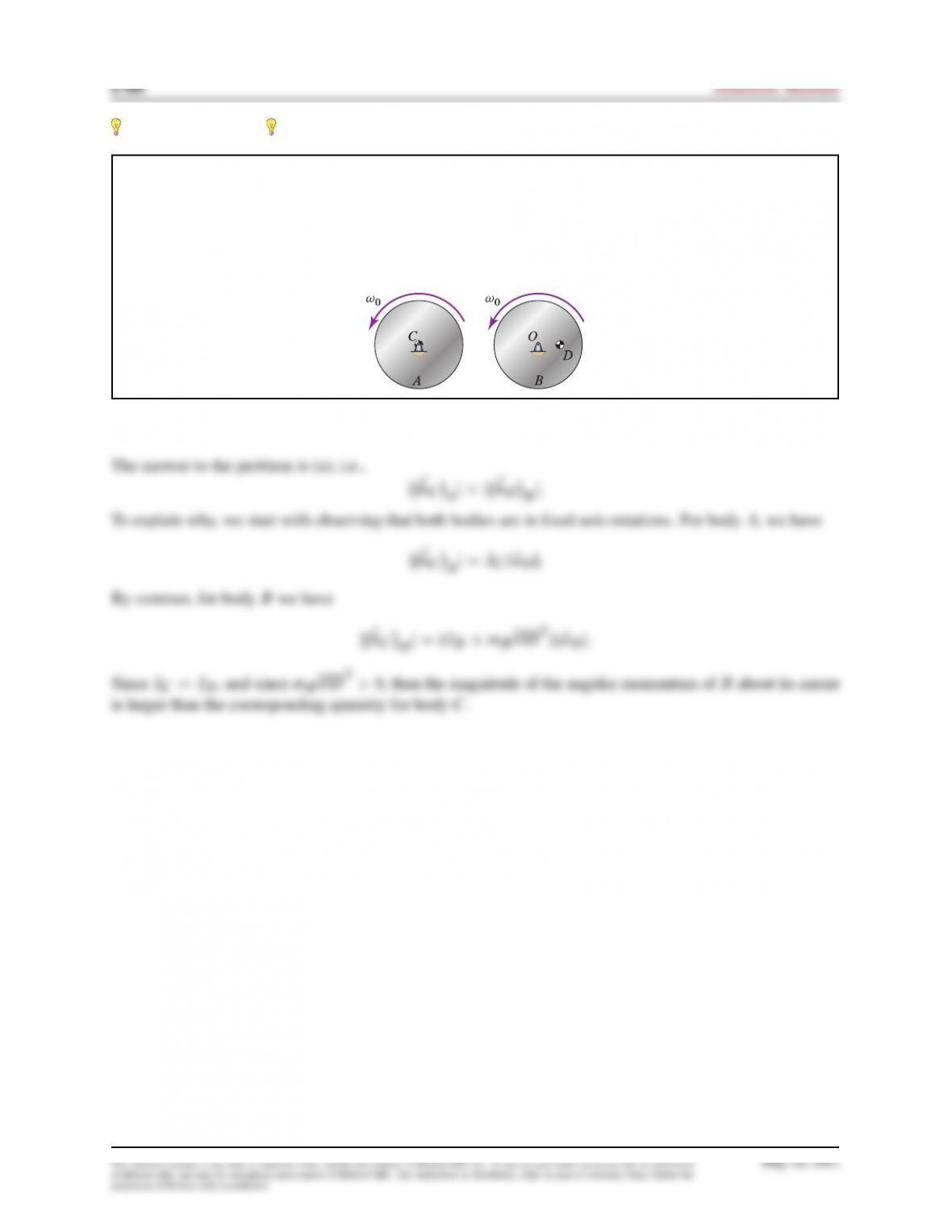
Problem 8.75
Disks
A
and
B
have identical masses and mass moments of inertia about their respective mass centers.
Point
C
is both the geometric center and center of mass of disk
A
. Points
O
and
D
are the geometric
center and center of mass of disk
B
, respectively. If, at the instant shown, the two disks are rotating about
their centers with the same angular velocity
!0
, determine which of the following statements is true and
why: (a) ˇˇE
hCAˇˇ<ˇˇE
hOBˇˇ, (b) ˇˇE
hCAˇˇDˇˇE
hOBˇˇ, (c) ˇˇE
hCAˇˇ>ˇˇE
hOBˇˇ.
Solution
of McGraw-Hill, and must be surrendered upon request of McGraw-Hill. Any duplication or distribution, either in print or electronic form, without the
permission of McGraw-Hill, is prohibited.
Dynamics 2e 1787
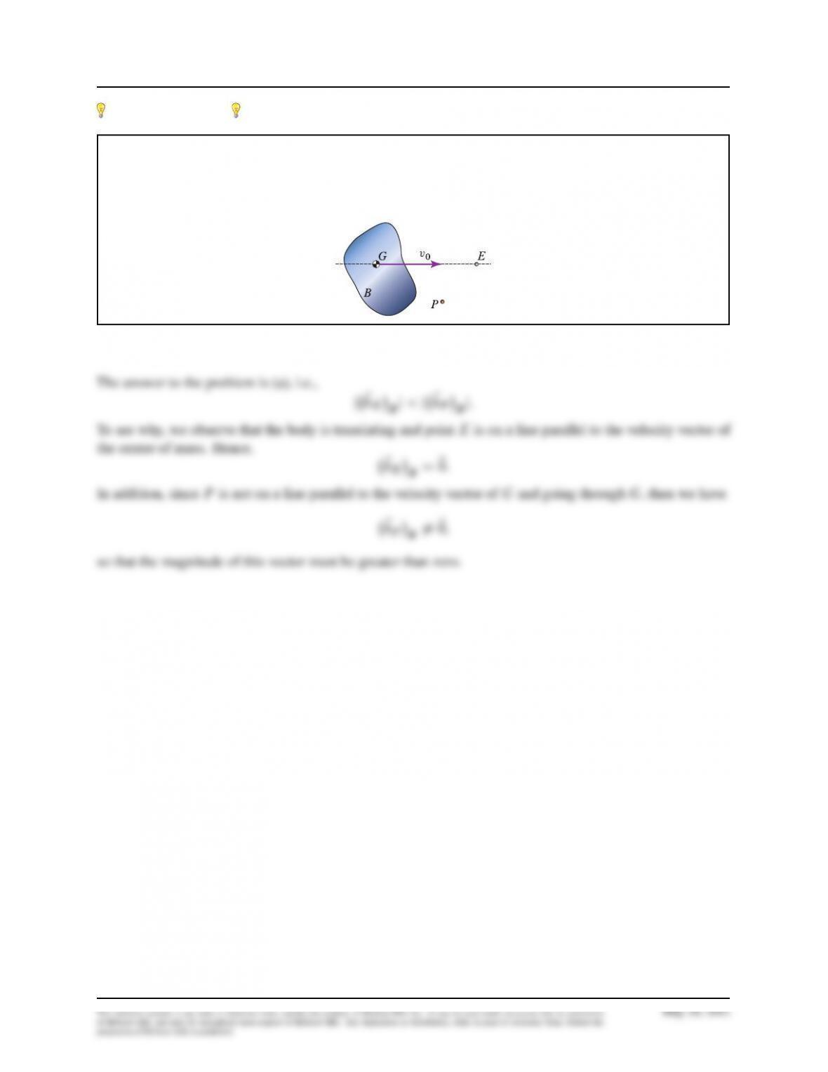
Problem 8.76
Body
B
has mass
m
and mass moment of inertia
IG
, where
G
is the mass center of
B
. If
B
is trans-
lating as shown, determine which of the following statements is true and why: (a)
ˇˇE
hEBˇˇ<ˇˇE
hPBˇˇ
,
(b) ˇˇE
hEBˇˇDˇˇE
hPBˇˇ, (c) ˇˇE
hEBˇˇ>ˇˇE
hPBˇˇ.
Solution
of McGraw-Hill, and must be surrendered upon request of McGraw-Hill. Any duplication or distribution, either in print or electronic form, without the
permission of McGraw-Hill, is prohibited.