Problem 8.69
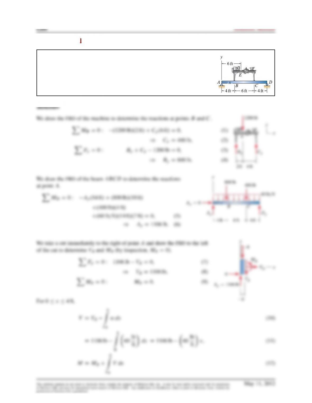
Beam
ABCD
is used to support a machine tool. The beam weighs
60 lb=ft
of length, and the machine weighs
1200 lb
with center of gravity at point
E
.
Assuming the machine applies only vertical forces to the beam at points
B
and
C
, determine the shear and moment within beam
ABCD
as functions of
position, and draw the shear and moment diagrams.
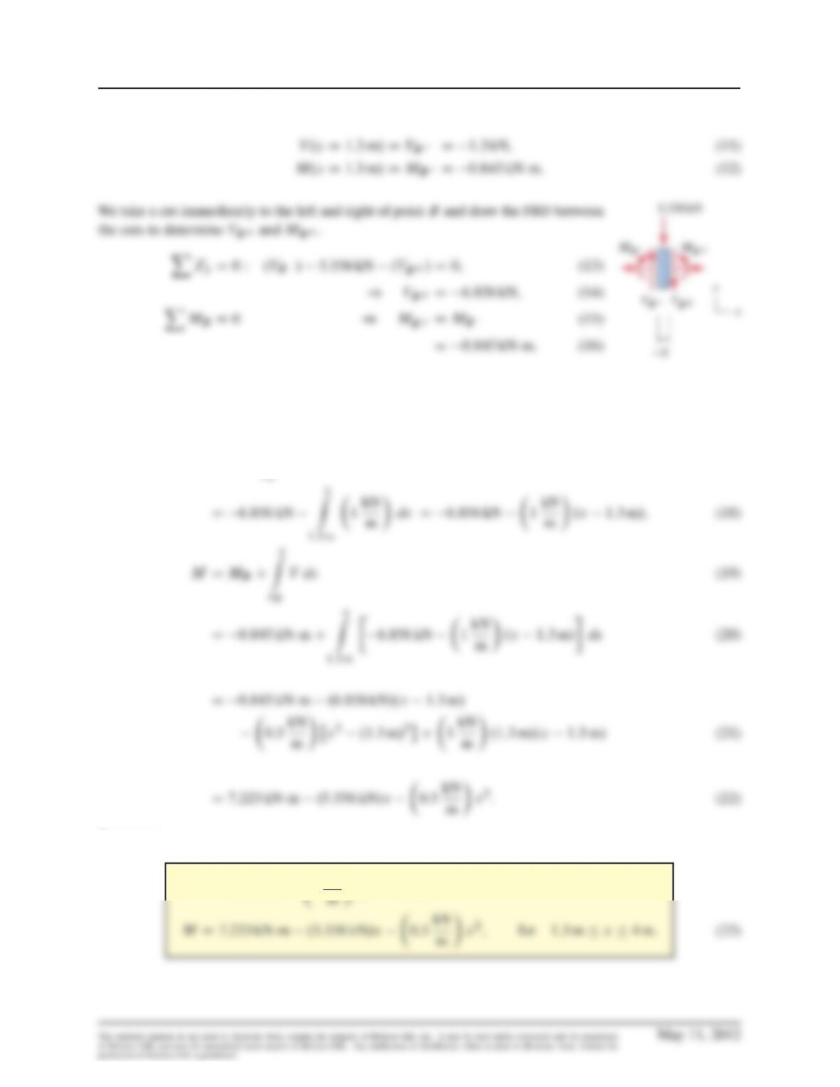
XMBD0)MBCDMB(19)
D3944 ftlb:(20)
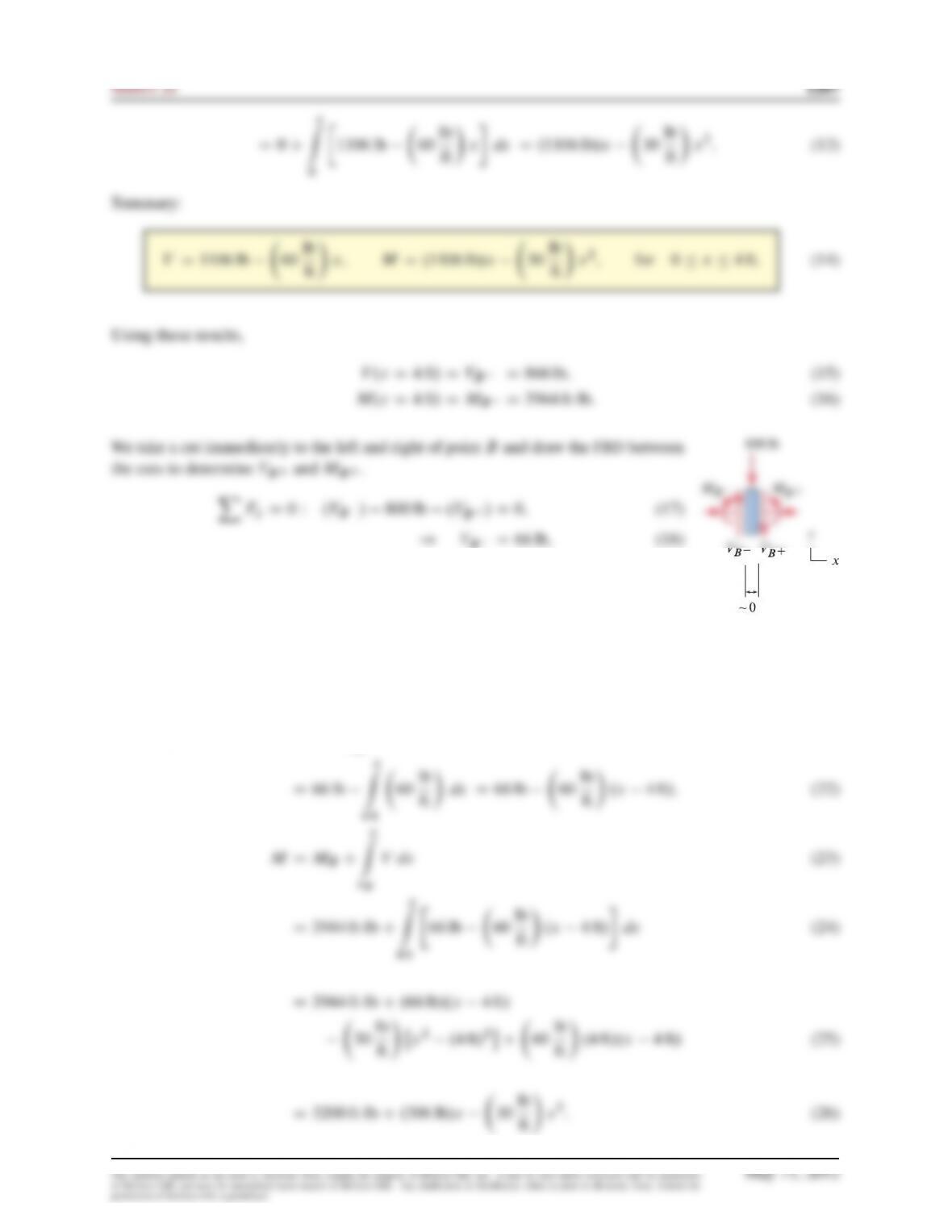
For 4ft x10 ft,
VDVB
x
Z
xB
wdx (21)
x
Z
60 lb

1268 Solutions Manual
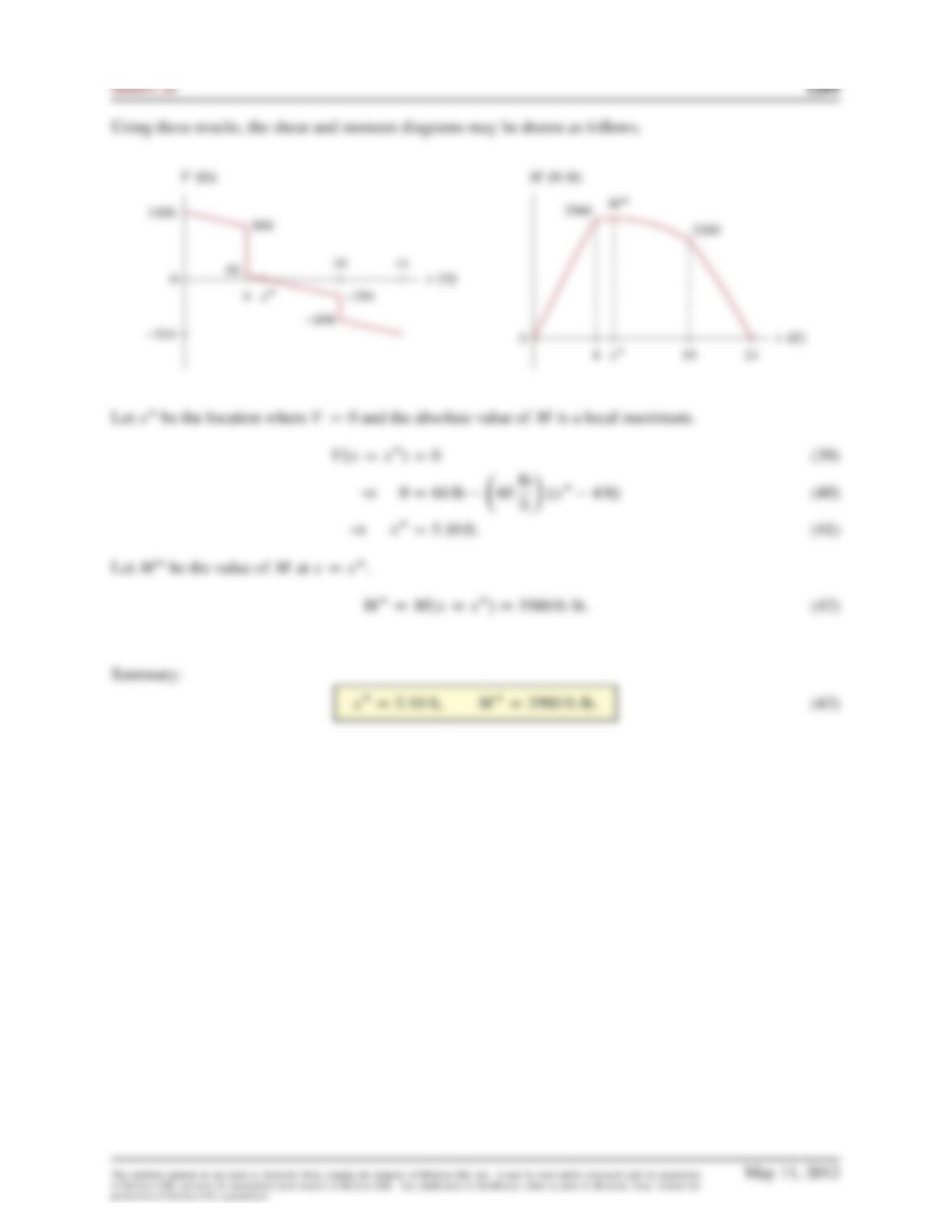
Summary:
VD66 lb 60 lb
VDVC
x
Z
xC
wdx (32)
D 694 lb
x
Z
60 lb
Problem 8.70
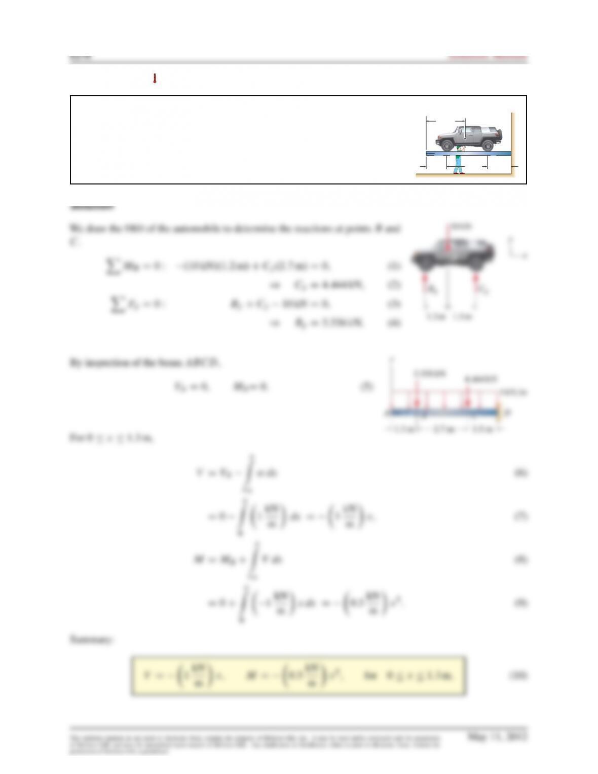
Beam
ABCD
is used to support an automobile so that it may be serviced. The
beam weighs
1kN=m
of length, and the automobile weighs
10 kN
with center
of gravity at point
E
. Assuming the automobile’s tires apply only vertical forces
to the beam at points
B
and
C
, determine the shear and moment as functions of
position, and draw the shear and moment diagrams.
AD
x
y
B
1.3 m 2.7 m2.7 m
C
1.5 m
2.5 m
E
E
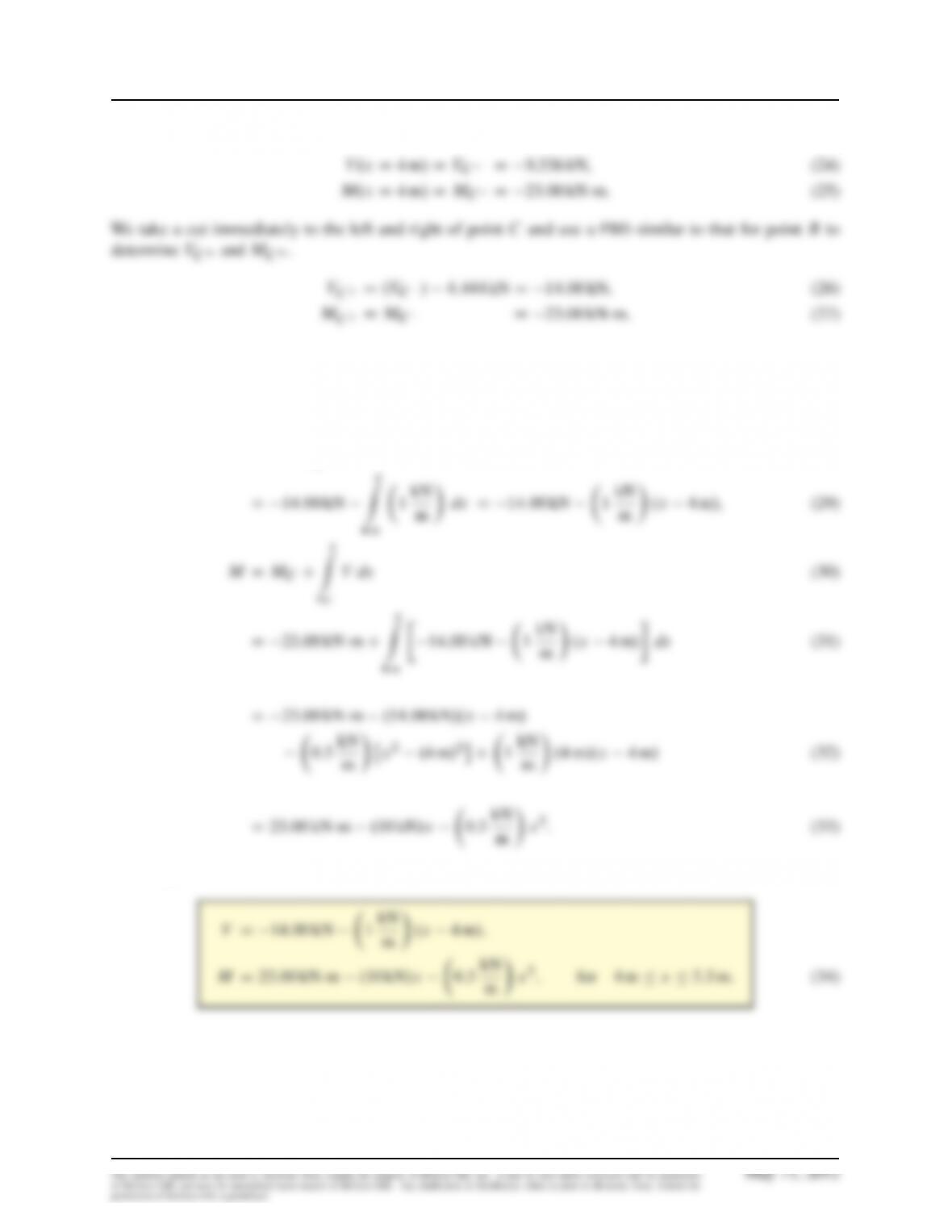
Statics 2e 1271
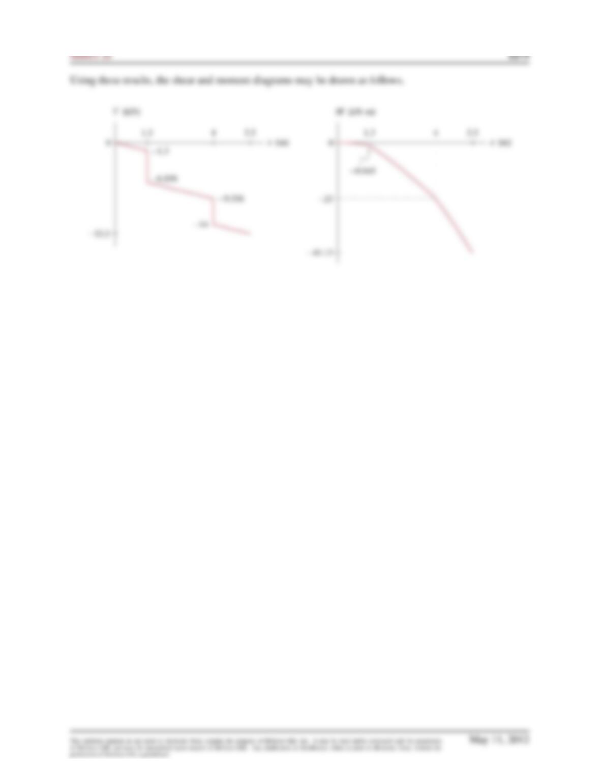
Using these results,
For 1:3 mx4m,
VDVB
x
Z
xB
wdx (17)
x
Z
1kN
Summary:
VD 6:856 kN 1kN
1272 Solutions Manual
Using these results,
For 4mx5:5 m,
VDVC
x
Z
xC
wdx (28)
x
Z
1kN
Summary:
Problem 8.71
Draw the shear and moment diagrams for the beam and loading shown. Determi-
nation of the shear and moment as functions of position is not required.
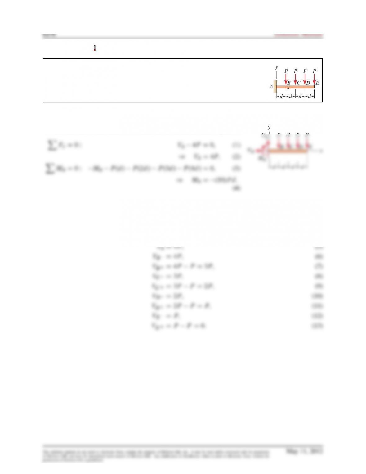
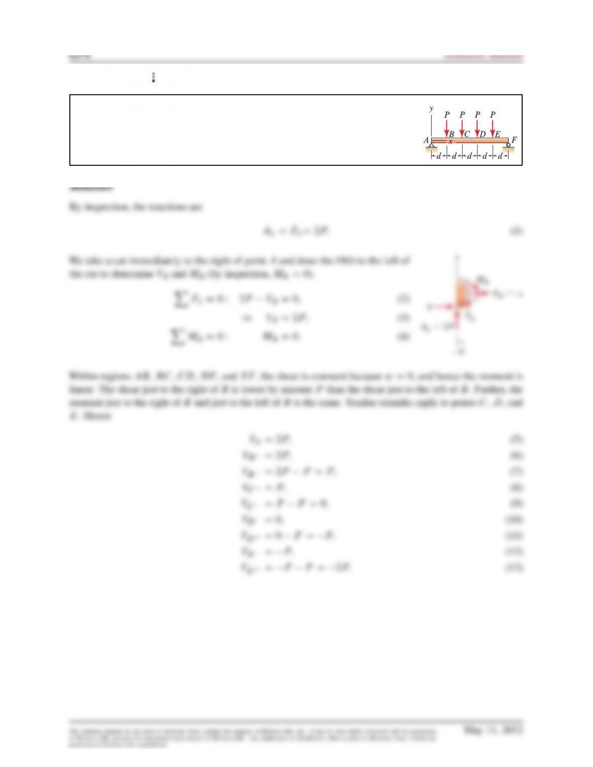
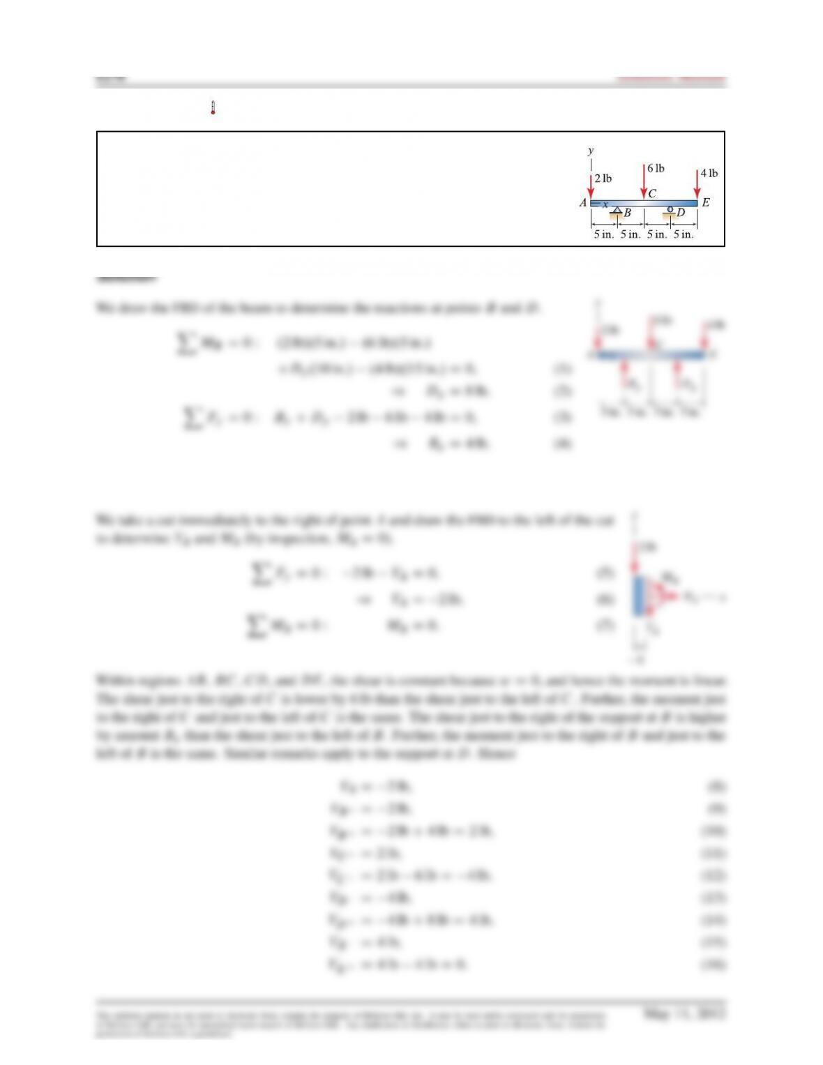
Problem 8.72
Draw the shear and moment diagrams for the beam and loading shown. Determination
of the shear and moment as functions of position is not required.
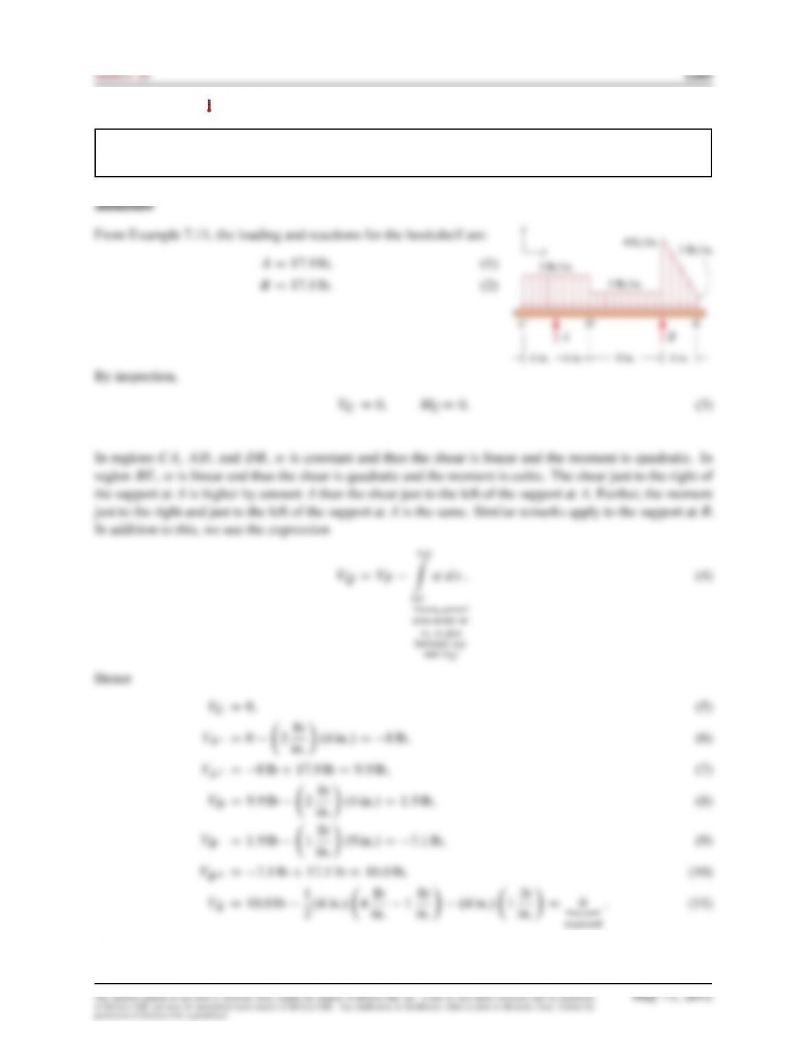
Solution
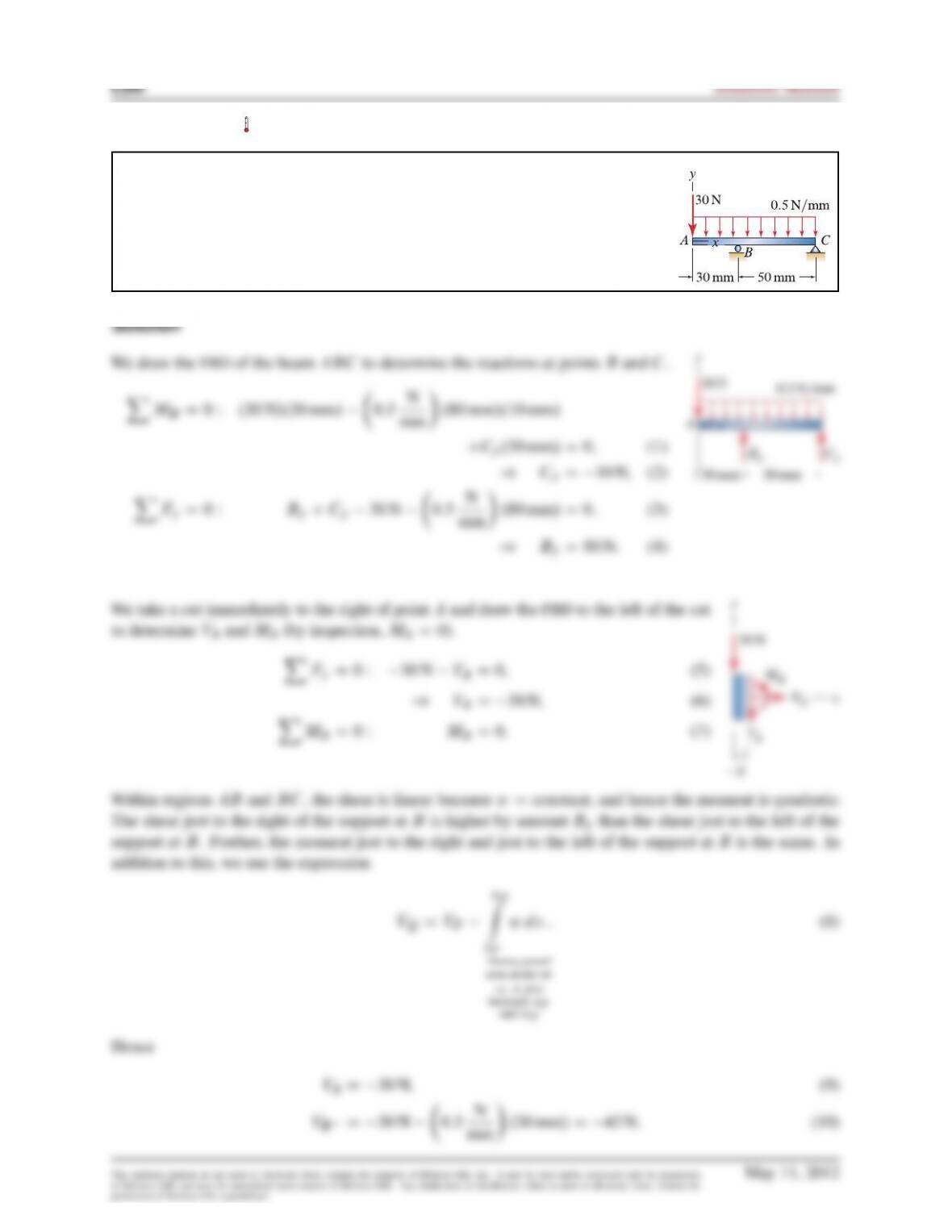
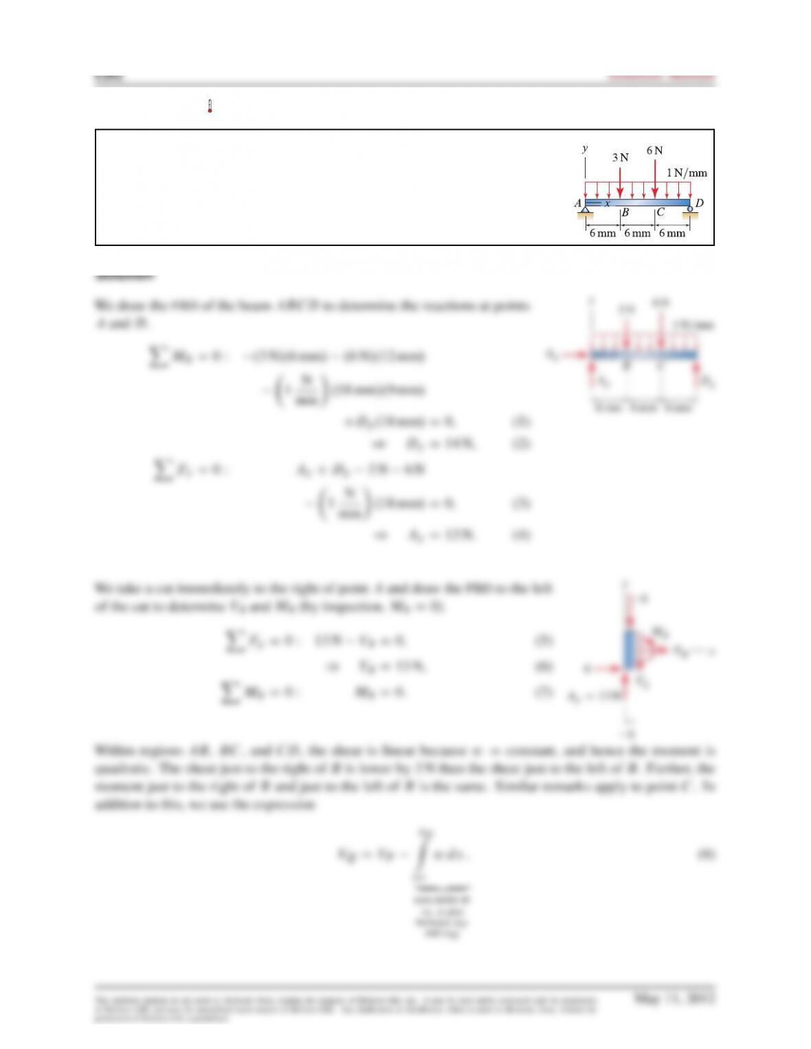
We draw the FBD of the beam to determine the shear and moment at point
A
.
Within regions
AB
,
BC
,
CD
, and
DE
, the shear is constant because
wD0
, and hence the moment is linear.
The shear just to the right of
B
is lower by amount
P
than the shear just to the left of
B
. Further, the moment
just to the right of
B
and just to the left of
B
is the same. Similar remarks apply to points
C
,
D
, and
E
.
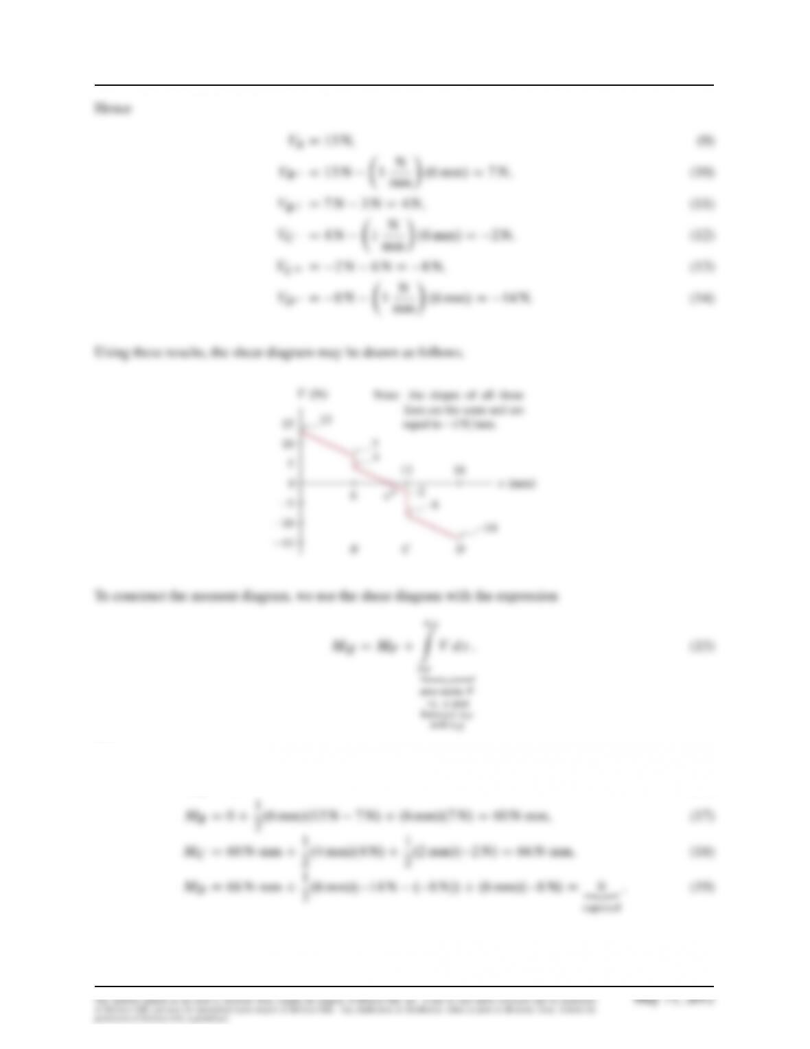
Hence
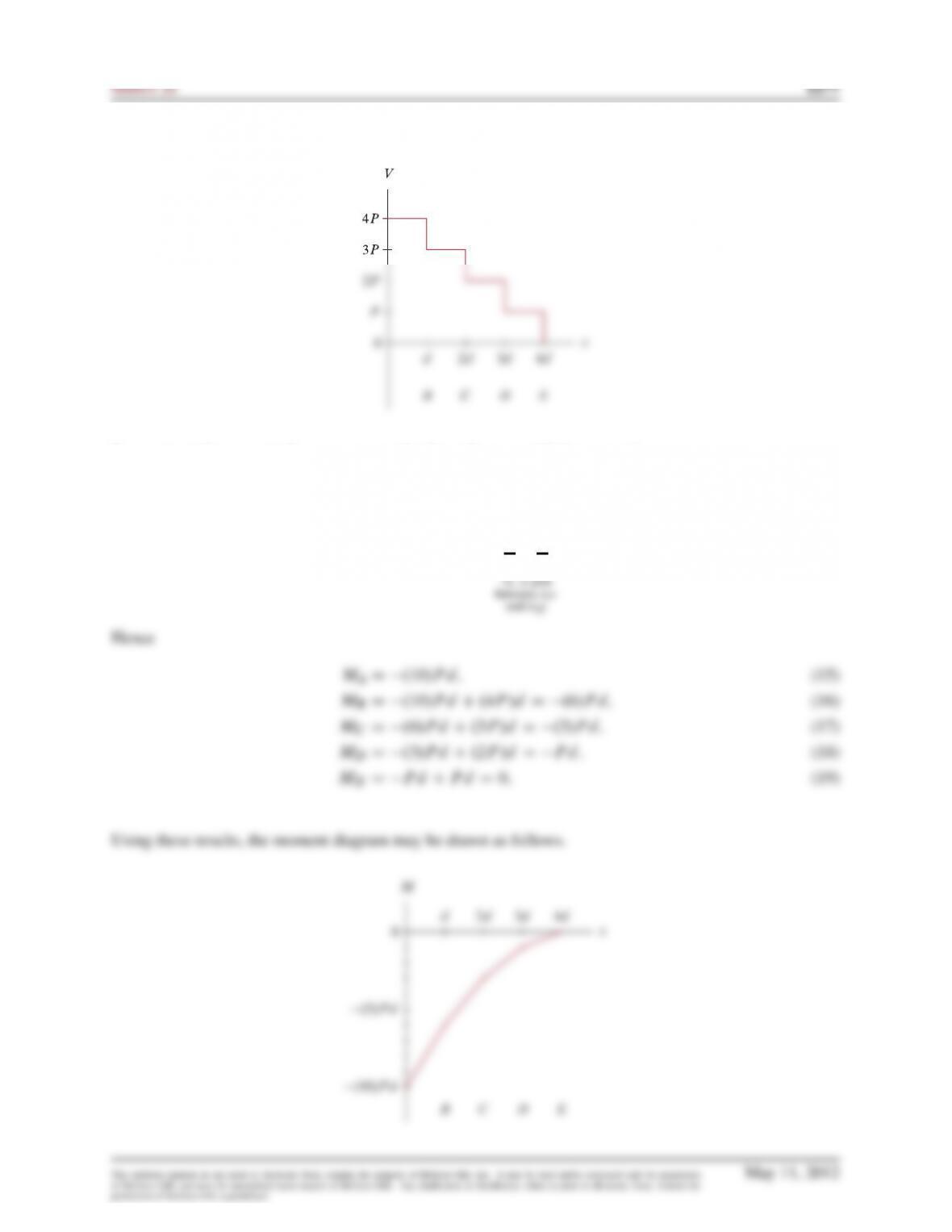
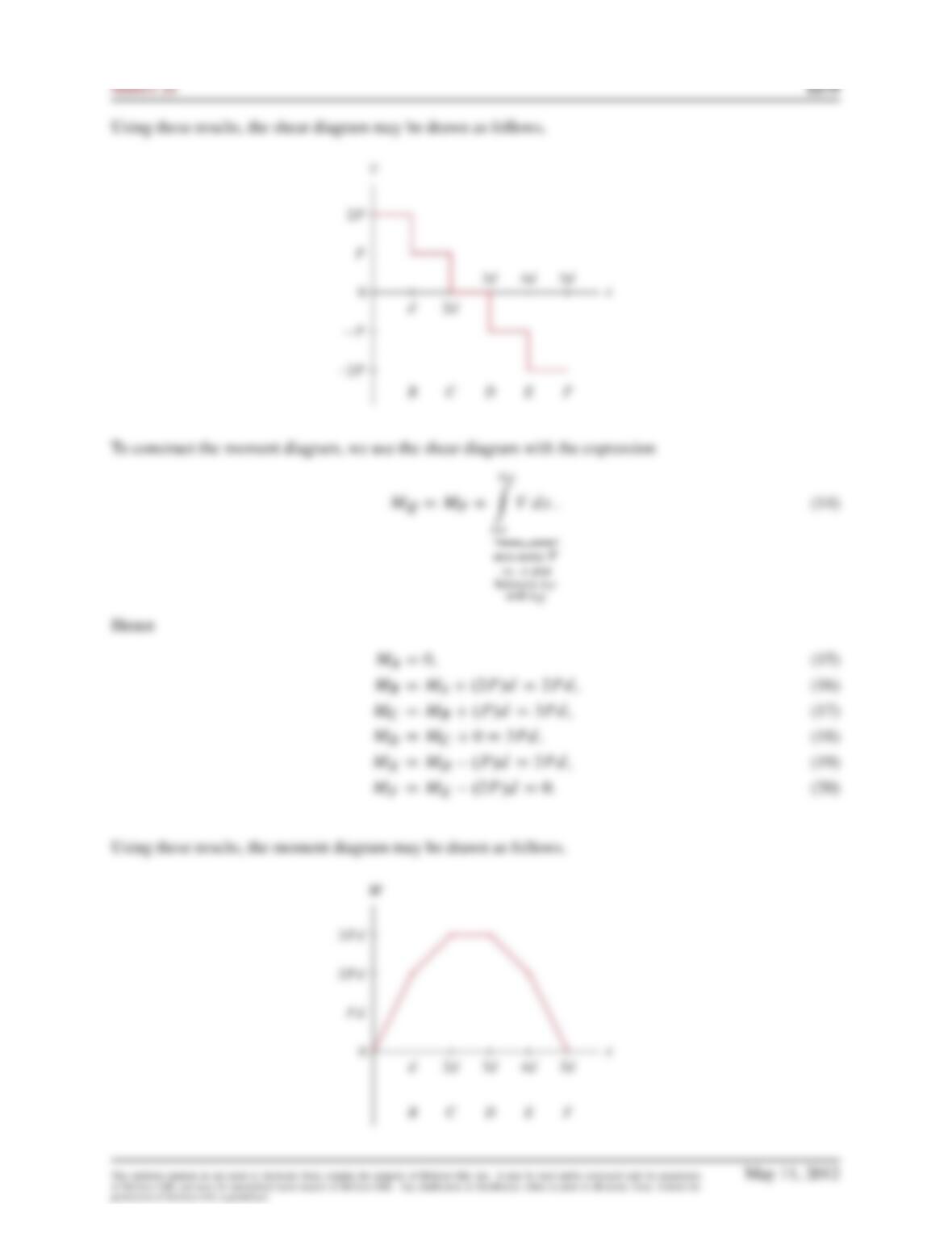
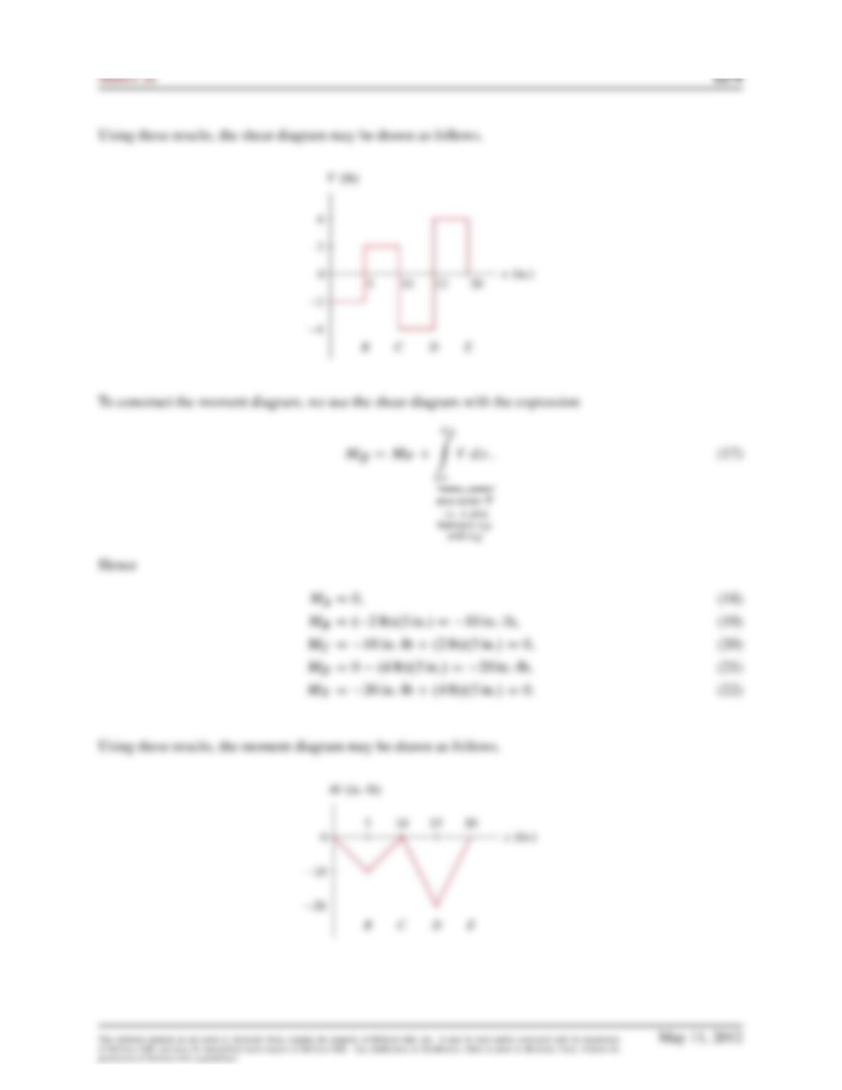
Using these results, the shear diagram may be drawn as follows.
To construct the moment diagram, we use the shear diagram with the expression
MQDMPC
xQ
Z
xP
V dx :
„ƒ‚ …
area under V
(14)
Problem 8.73
Draw the shear and moment diagrams for the beam and loading shown. Determi-
nation of the shear and moment as functions of position is not required.
Problem 8.74
Draw the shear and moment diagrams for the beam and loading shown. Determi-
nation of the shear and moment as functions of position is not required.
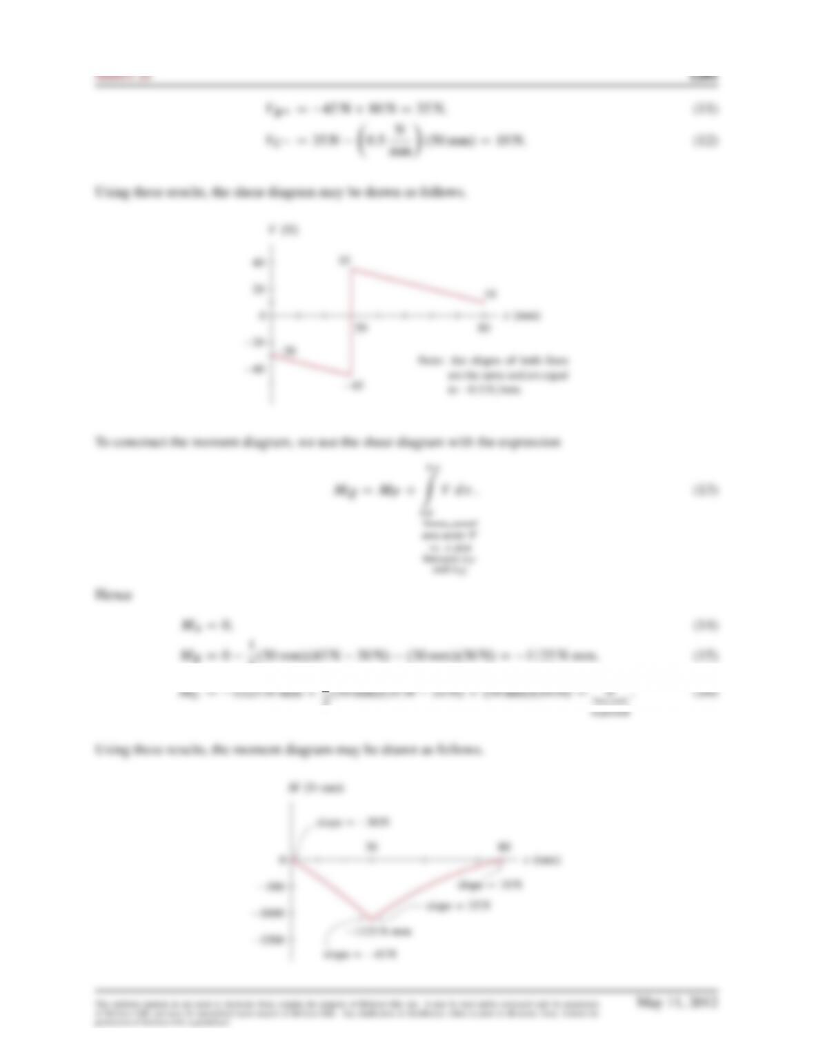
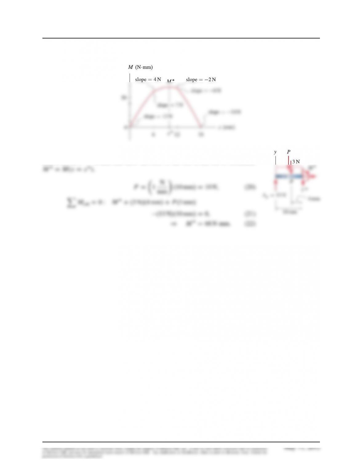
2.30 mm/.45 N30 N/.30 mm/.30 N/D 1125 Nmm;(15)
Problem 8.75
Draw the shear and moment diagrams for the beam and loading shown. Determi-
nation of the shear and moment as functions of position is not required.
Statics 2e 1283
xP
„ƒ‚ …
area under V
vs. xplot
between xP
and xQ
Hence
MAD0; (16)
1284 Solutions Manual
Using these results, the moment diagram may be drawn as follows.
Using similar triangles applied to the shear diagram provides
xD10 mm
. We
take a cut at
xD10 mm
and draw the FBD to the left of the cut to determine
Problem 8.76
Draw the shear and moment diagrams for the bookshelf shown in Fig. 1 of Example 7.11 on p. 475.
Determination of the shear and moment as functions of position is not required.