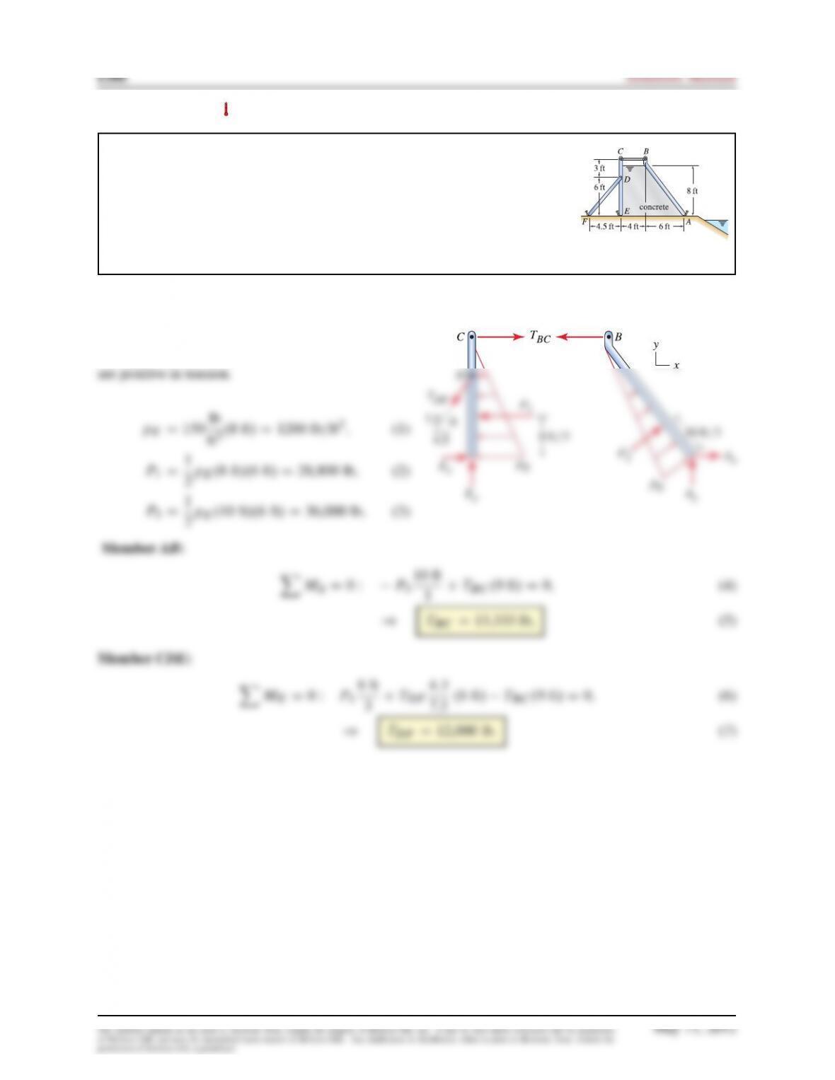
Problem 7.112
A breakwater along an oceanfront is to be constructed of concrete, and the
formwork for retaining the concrete while it is poured is shown. For every 6ft
of width (into the plane of the figure), the formwork has a horizontal support
BC
and a support
DF
. The stakes at points
A
,
E
, and
F
may be modeled as
pins, and the weights of all members except the concrete may be neglected. If
the concrete is modeled as a fluid with
150 lb=ft3
specific weight, determine the
force supported by members BC and DF .
Solution
The FBDs for members AB and CDE are shown at
the right, where the forces in members BC and DF
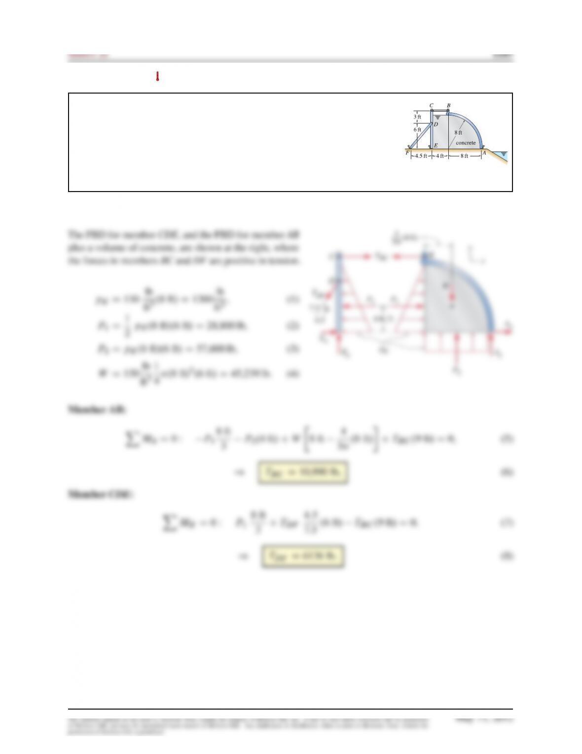
Problem 7.113
A breakwater along an oceanfront is to be constructed of concrete, and the
formwork for retaining the concrete while it is poured is shown. For every 6ft
of width (into the plane of the figure), the formwork has a horizontal support
BC
and a support
DF
. The stakes at points
A
,
E
, and
F
may be modeled as
pins, and the weights of all members except the concrete may be neglected. If
the concrete is modeled as a fluid with
150 lb=ft3
specific weight, determine the
force supported by members BC and DF .
Solution
Problem 7.114
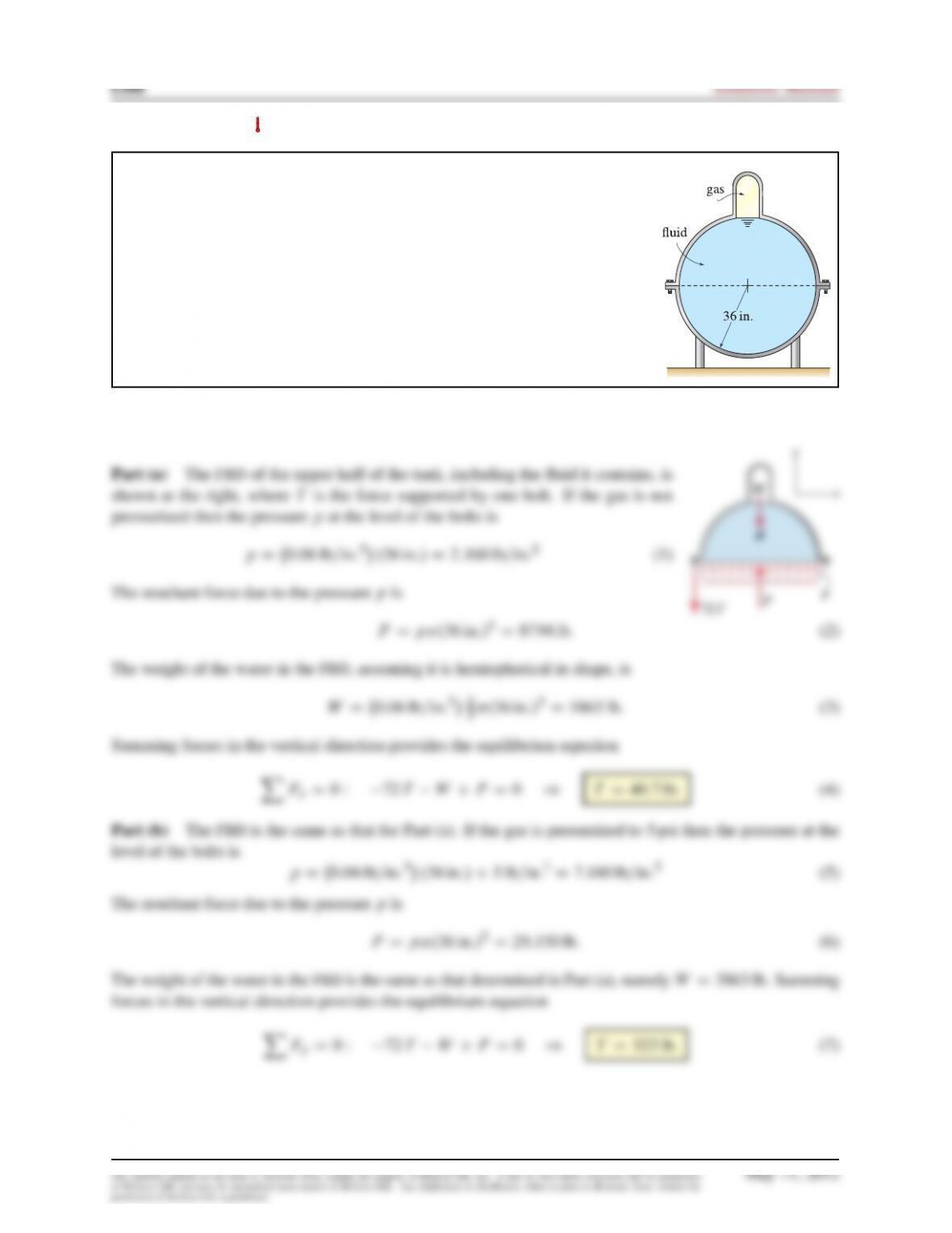
The cross section through a spherical tank is shown. The upper and lower
portions of the tank are attached using 72 bolts that are uniformly spaced
around the perimeter of the tank. The upper portion of the tank has a small
dome that contains a gas. The fluid in the tank has specific weight of
0:06 lb=in:3
and approximately spherical shape. Assuming all the bolts support the same
force, determine the force each bolt supports due to the fluid and gas pressures
if:
(a) The gas is not pressurized (i.e., it is at atmospheric pressure).
(b) The gas is pressurized to 5psi.
Solution

Problem 7.115
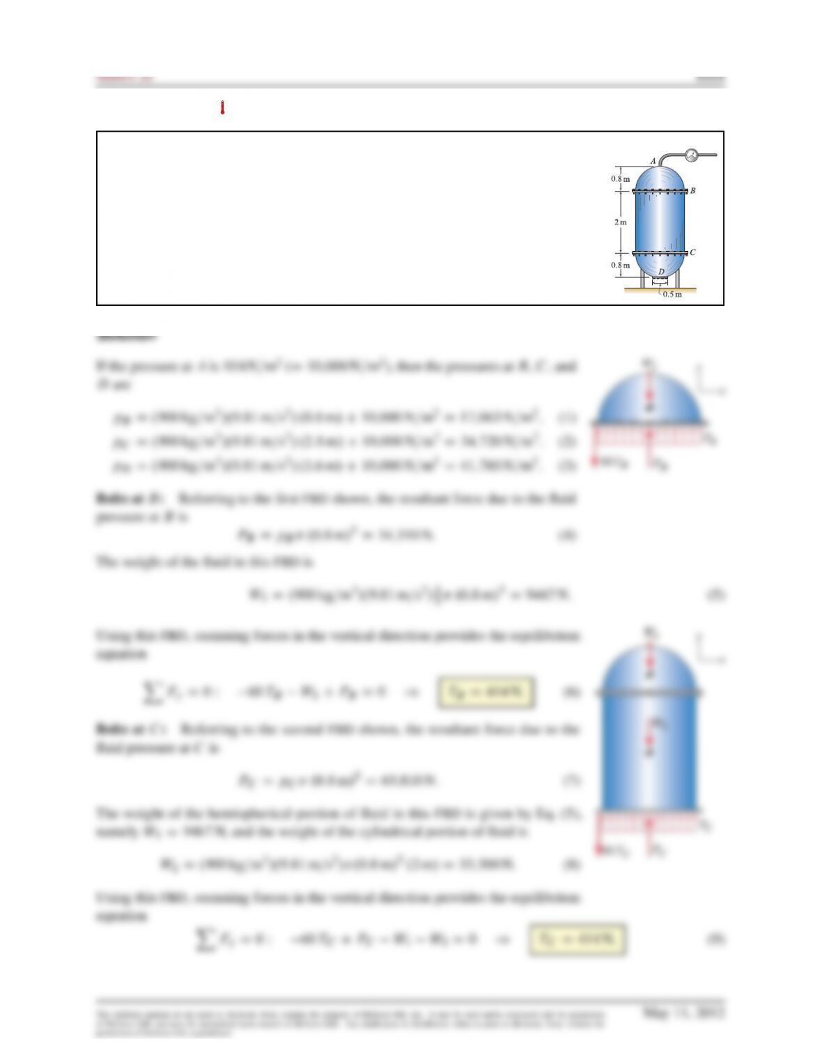
The tank shown has a cylindrical midsection with hemispherical ends. Each of
the hemispherical ends is attached to the cylindrical midsection using 60 bolts
that are uniformly spaced around the perimeter of the tank. At
D
, the tank has
a circular access plate that is attached using 12 bolts that are uniformly spaced.
The tank is fully filled with a fluid having density
900 kg=m3
. Assume that each
of the bolts at
B
supports the same force, each of the bolts at
C
supports the
same force, and each of the bolts at
D
supports the same force. However, the
forces supported by the bolts at
B
,
C
, and
D
are probably different. Assume the
piping that enters the tank at
A
is flexible and has negligible weight. Determine
the force each bolt supports due to the fluid pressure if the fluid at
A
is at
atmospheric pressure.
Solution
Problem 7.116
Repeat Prob. 7.115 if the fluid at Ais at 10 kN=m2pressure.
Problem 7.117
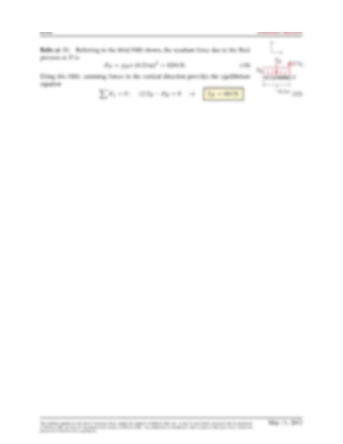
The cross section through the valve of a fuel injector for an engine is shown,
where the tip of the valve has conical shape. If the fuel is at
500 kN=m2
pressure,
determine the force
F
that must be applied to keep the valve closed. Hint: The
pressure due to weight of the fuel is negligible compared to 500 kN=m2.
Problem 7.118
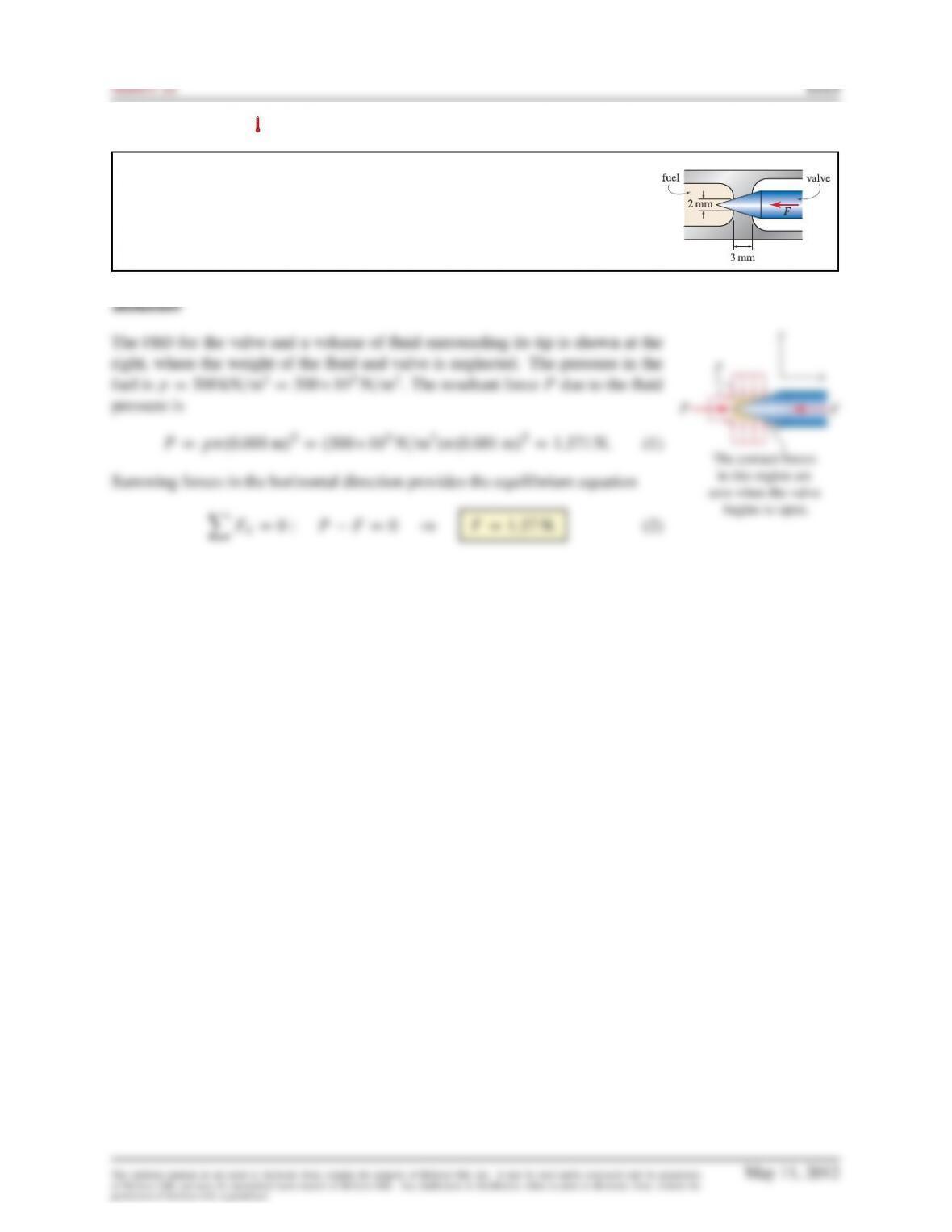
Grain is contained in a silo. The walls of the silo are fixed, and the door
ABCD
can be opened to allow the grain to pour out. Door
ABCD
is flat, with
8in:
depth (into the plane of the figure). Idealize the grain to be a fluid with
0:025 lb=in:3
specific weight. In the position shown, the hydraulic cylinder
EG
is horizontal. Neglect the weights of the individual members. Determine the
force the hydraulic cylinder
EG
must support to keep the door in equilibrium.
Report your answer, using a positive value for tension in the hydraulic cylinder
and a negative value for compression.
Solution
Using the FBD for the hydraulic cylinder
EG
, we sum forces in the
x
and
y
directions to obtain the
equilibrium equations
Problem 7.119
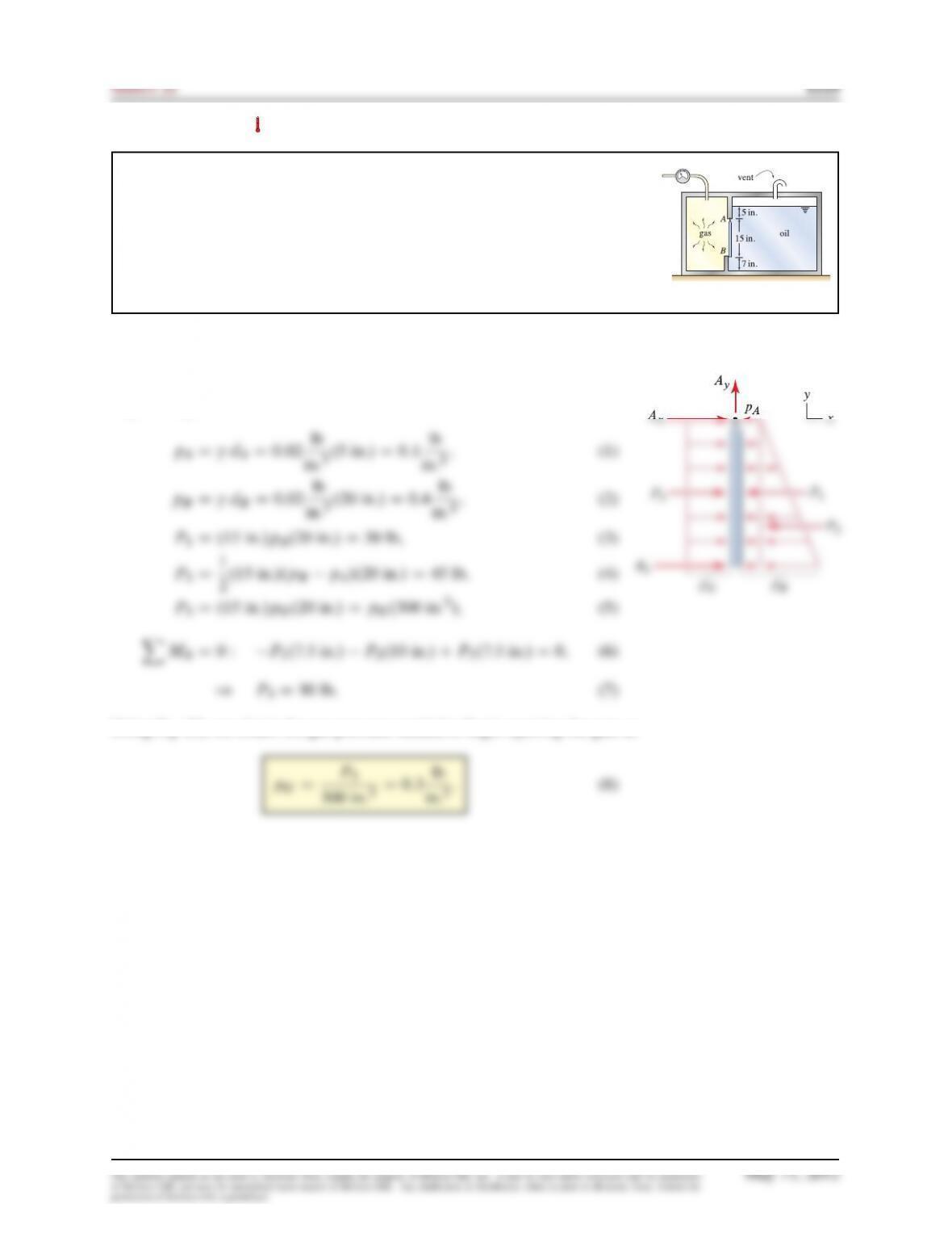
A tank with two compartments contains pressurized gas on the left and oil on
the right that are separated by a gate
AB
having
20 in:
width into the plane
of the figure. The gate is supported by a hinge at
A
and a stop at
B
. The oil
compartment is vented so that the surface of the oil is subjected to atmospheric
pressure. Determine the value of the gas pressure that will cause the gate to
begin to open. The specific weight of the oil is
0:02 lb=in:3
, and the specific
weight of the gas is negligible.
Solution
The FBD for the gate is shown at the right, where
BxD0
when the gate
begins to open.
Using Eq. (5), we obtain the gas pressure needed to begin opening the gate as
Problem 7.120
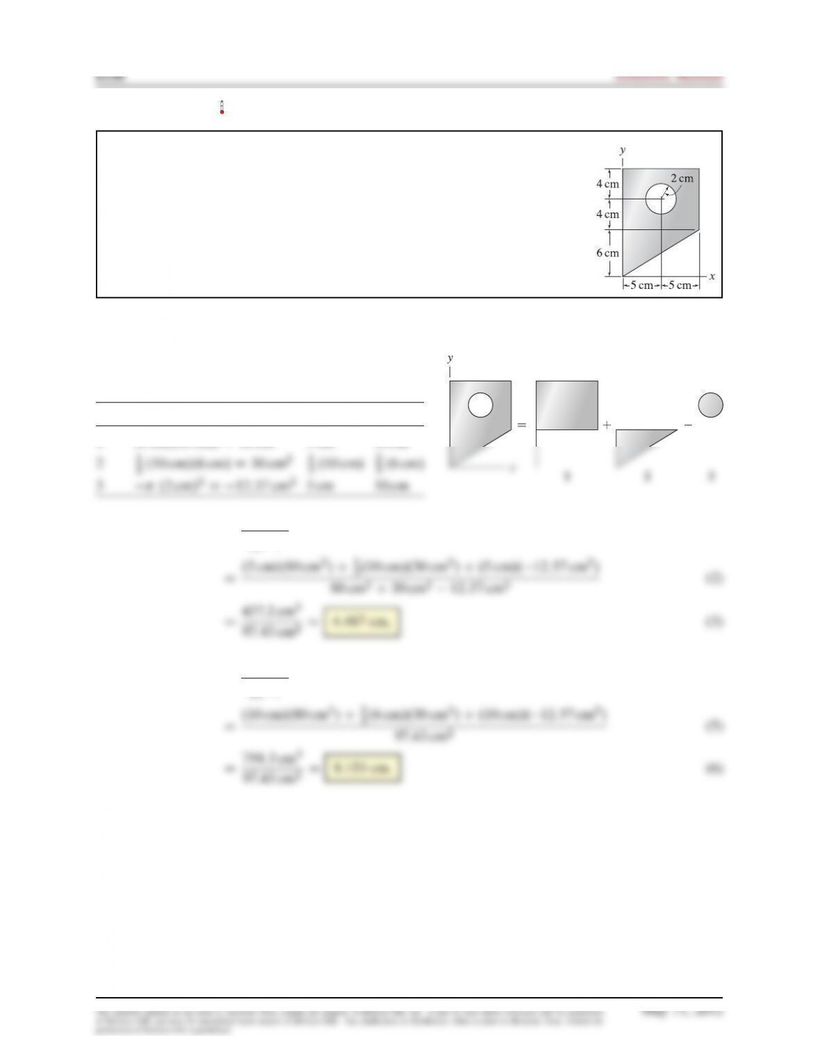
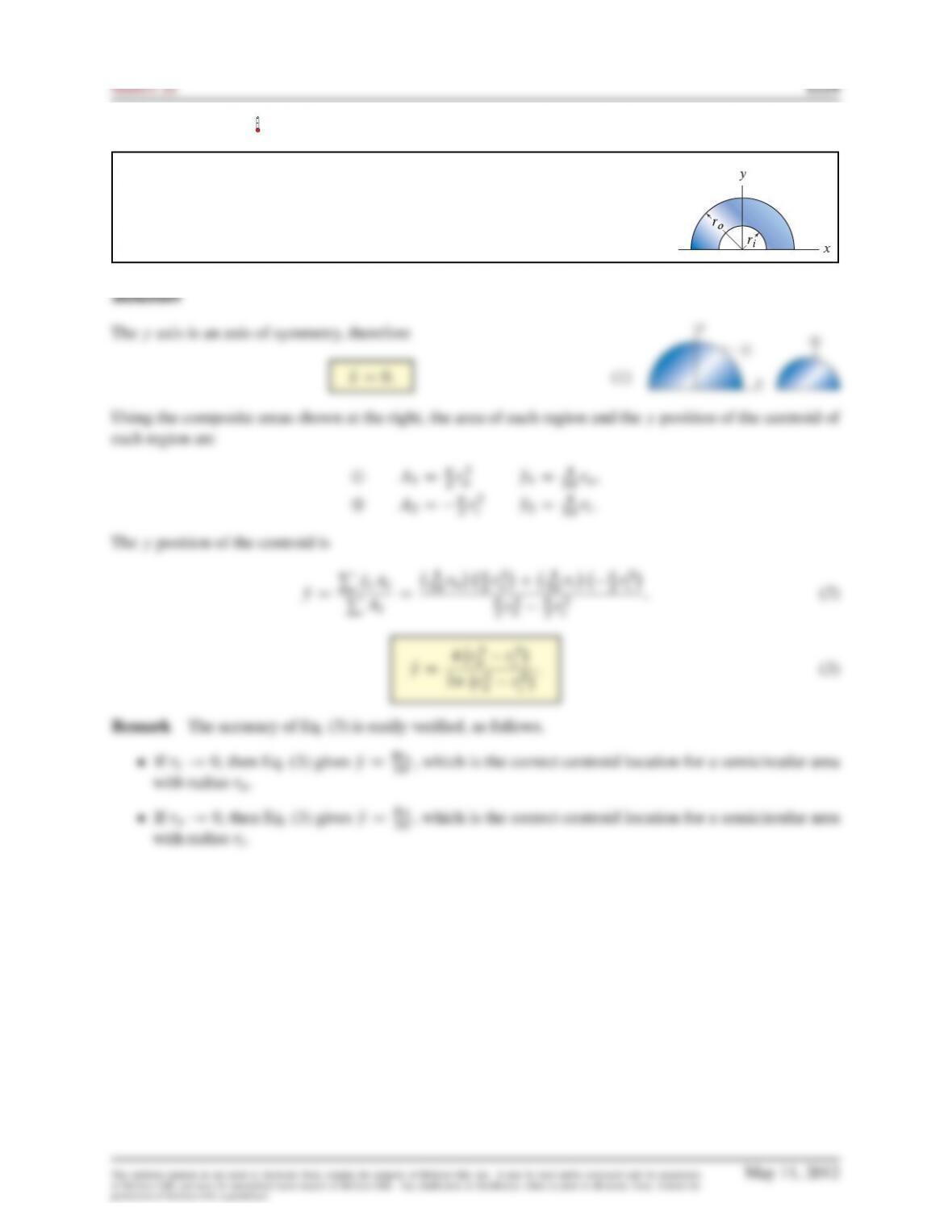
For the area shown, use composite shapes to determine the
x
and
y
positions of the
centroid.
Solution
Using the composite areas shown at the right, the area of
each region and the position of its centroid are
Area AiQxiQyi
1.8 cm/.10 cm/D80 cm25cm 10 cm
NxDPQxiAi
PAi
(1)
3.10 cm/.30 cm2/C.5 cm/.12:57 cm2/
NyDPQyiAi
PAi
(4)
3.6 cm/.30 cm2/C.10 cm/.12:57 cm2/
Problem 7.121
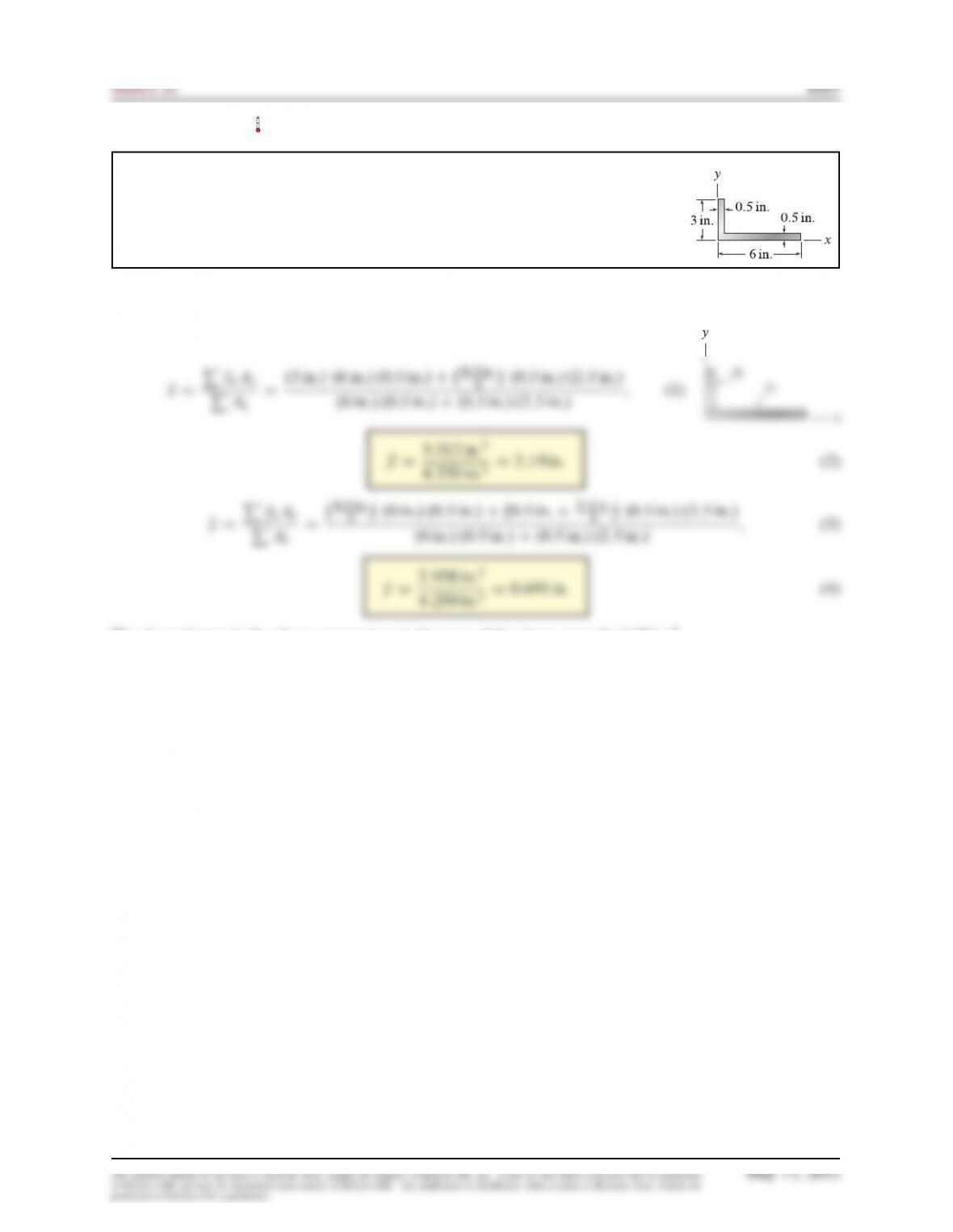
For the area shown, use composite shapes to determine the
x
and
y
positions of the
centroid.
Solution
Using the two composite shapes shown, the xand ypositions of the centroid are
2.0:5 in:/ .2:5 in:/
The denominator in the above expressions is the area of the shape, namely 4:25 in:2.
Problem 7.122
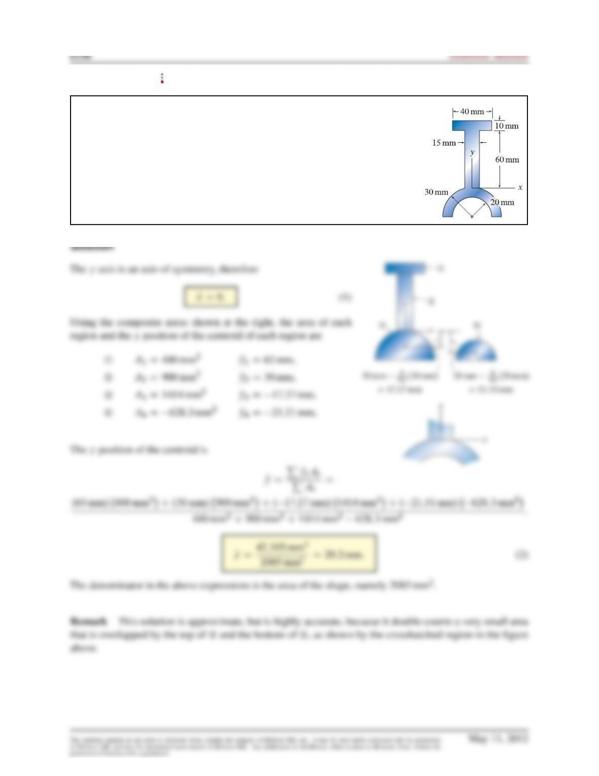
For the area shown, use composite shapes to determine the
x
and
y
positions of
the centroid.
Problem 7.123
For the area shown, use composite shapes to determine the
x
and
y
positions of
the centroid.
Problem 7.124
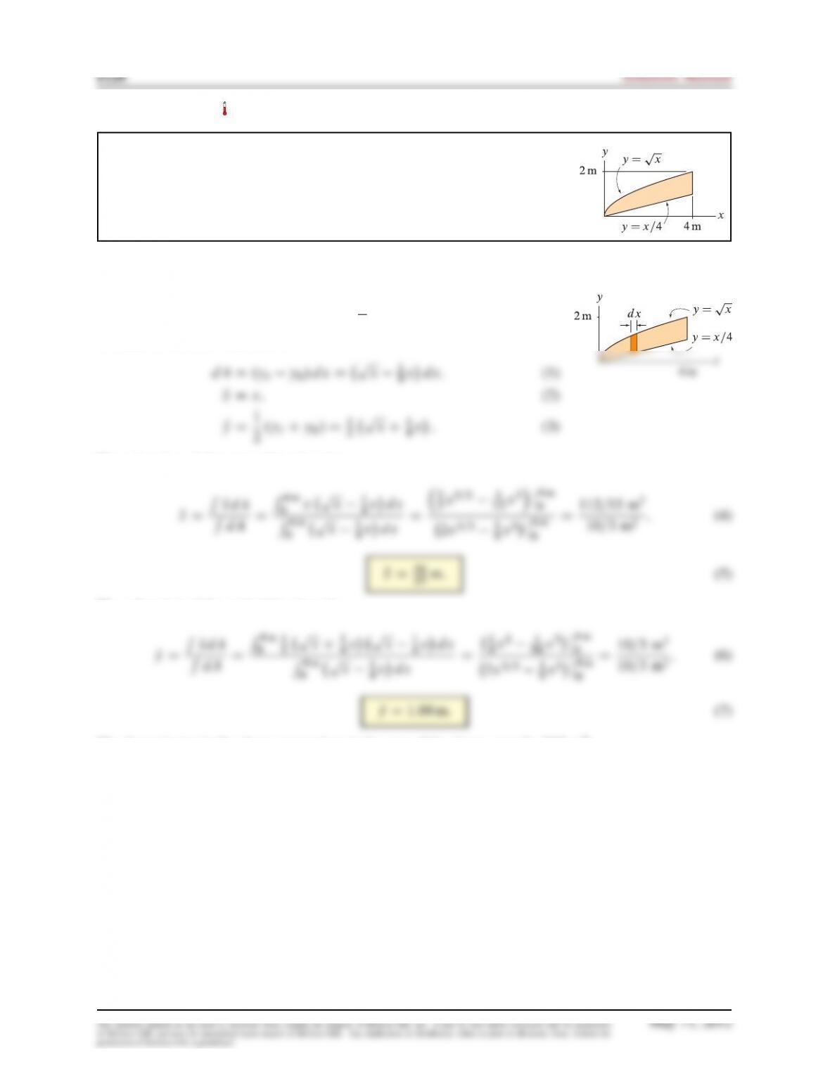
For the area shown, use integration to determine the
x
and
y
positions of the
centroid.
Solution
For the area of this problem, a vertical area element is more convenient than a
horizontal area element. Thus, with
ytDpx
and
ybDx=4
, the area element
dA, and its centroid Qxand Qyare
2.ytCyb/D1
The xlocation of the centroid is given by
0xpx1
4xdx
5x5=2 1
12 x3ˇ
ˇ
4m
0
The ylocation of the centroid is given by
0
1
2pxC1
4xpx1
4xdx
4x21
96 x3ˇ
ˇ
4m
0
The denominator in the above expressions is the area of the shape, namely 10/3 m2.
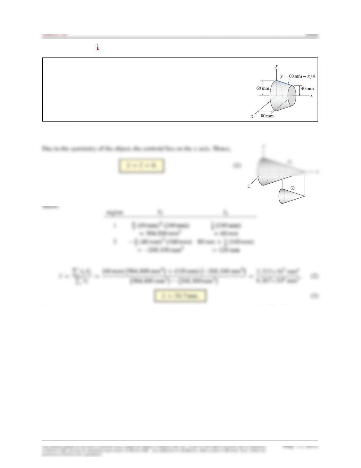
Problem 7.125
For the truncated circular cone shown, use composite shapes to determine the
location of the centroid.
Solution
The
x
position of the centroid will be determined using the method of compos-
ite shapes where the object is divided into the two regions shown in the figure.
For each region, the volume
Vi
and its centroid
Qxi
are summarized in the table
The denominator in the above expressions is the volume of the object, namely 6:367105mm3.
Problem 7.126
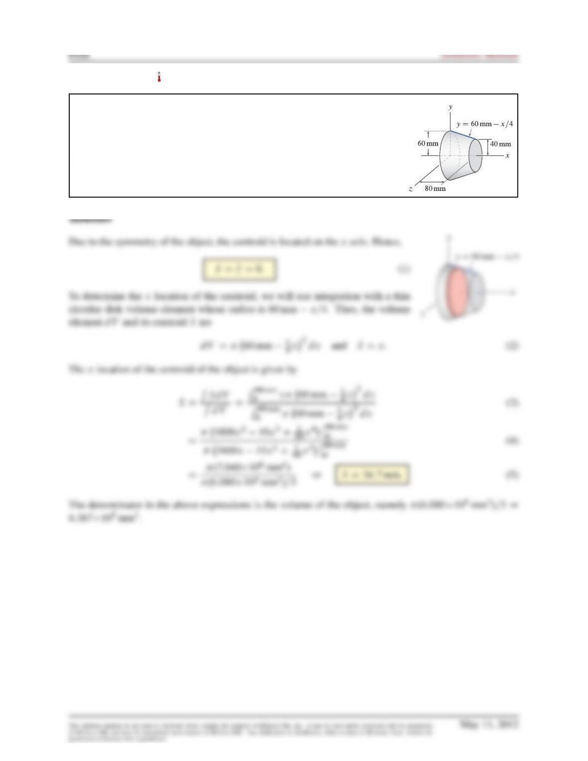
For the truncated circular cone shown, use integration to determine the location
of the centroid.
Problem 7.127
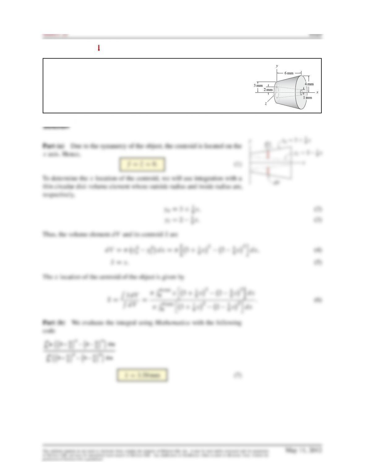
The truncated circular cone shown has a truncated conical hole.
(a)
Fully set up the integral, including the limits of integration, that will yield
the centroid of the object.
(b)
Evaluate the integral determined in Part (a) using computer software such
as Mathematica or Maple.
Problem 7.128
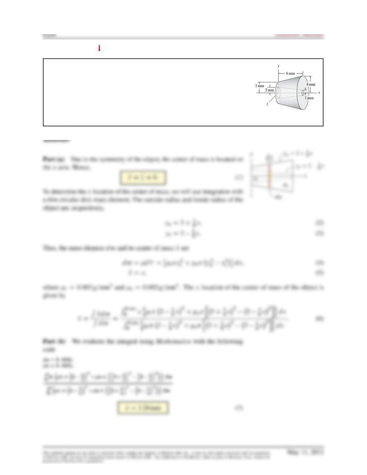
The truncated circular cone shown has a truncated conical hole and is made
of a material with density
0:002 g=mm3
. Let the conical hole be filled with a
material with density 0:003 g=mm3.
(a)
Fully set up the integral, including the limits of integration, that will yield
the center of mass of the object.
(b)
Evaluate the integral determined in Part (a) using computer software such
as Mathematica or Maple.
Problem 7.129
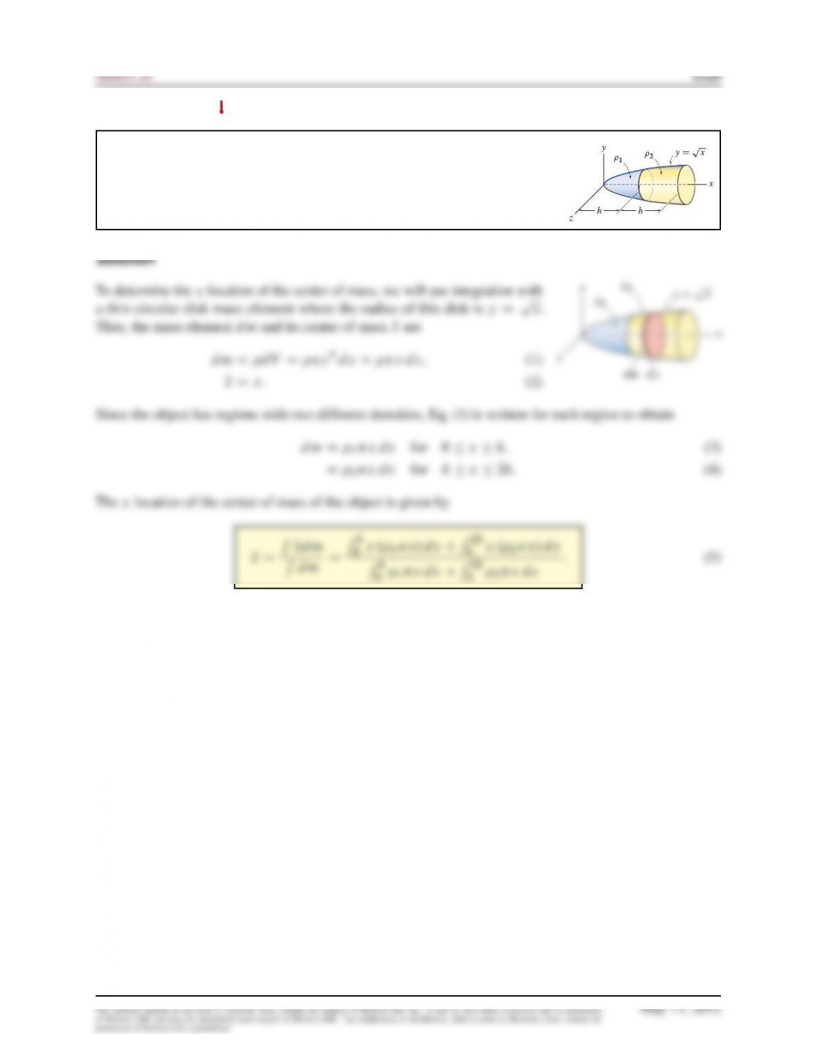
The bullet-shaped object is a solid of revolution that is composed of materials
with densities
1
and
2
. Set up the integral, including the limits of integration,
that will yield the xposition of the center of mass.