38
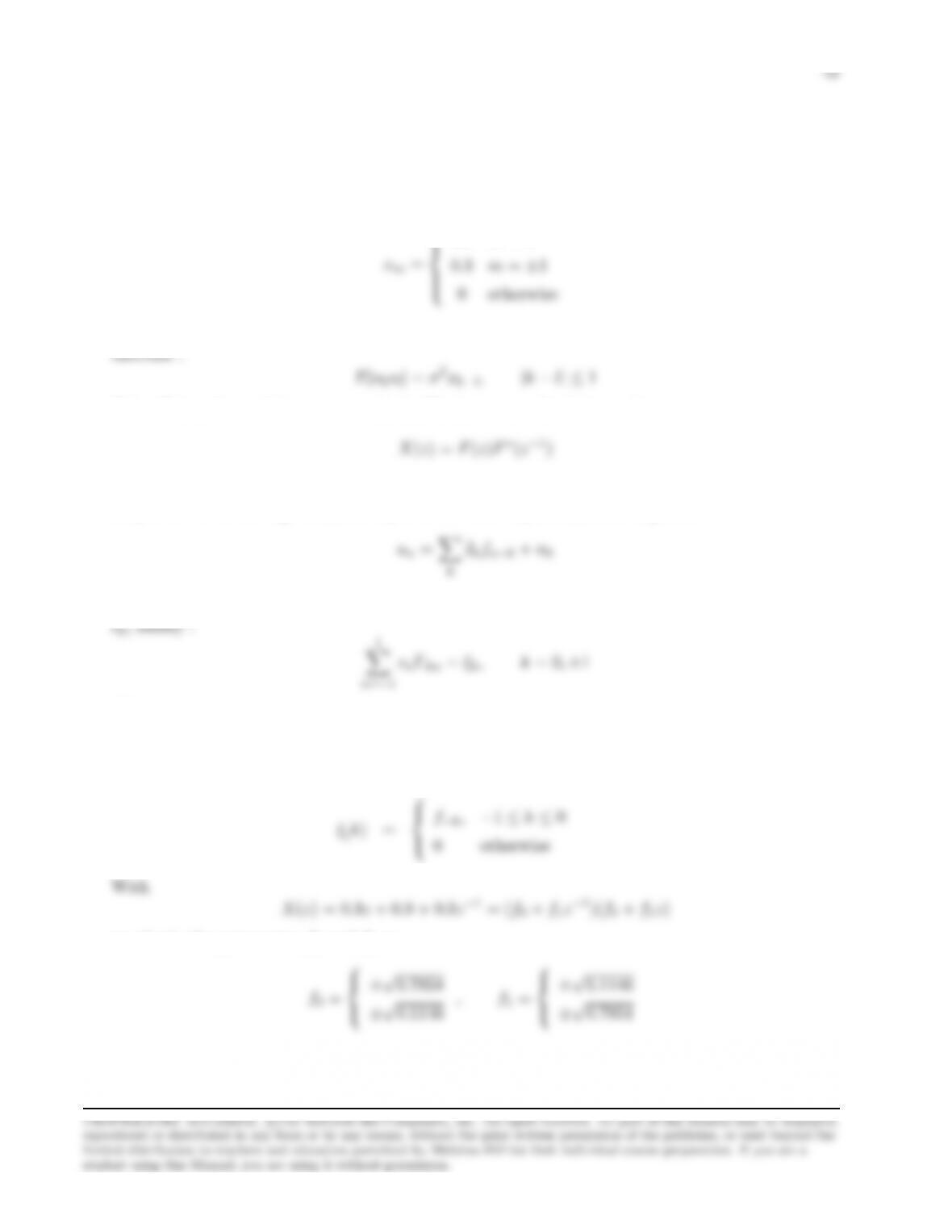
Thus, the autocorrelation function of the noise at the output of the equalizer is :
where c(k) denotes the discrete time impulse response of the equalizer. Therefore, the autocorrela-
tion sequence of the noise at the output of the equalizer is :
1.3577 k=±1
0.1956 k=±3
0.0283 k=±4
0 otherwise
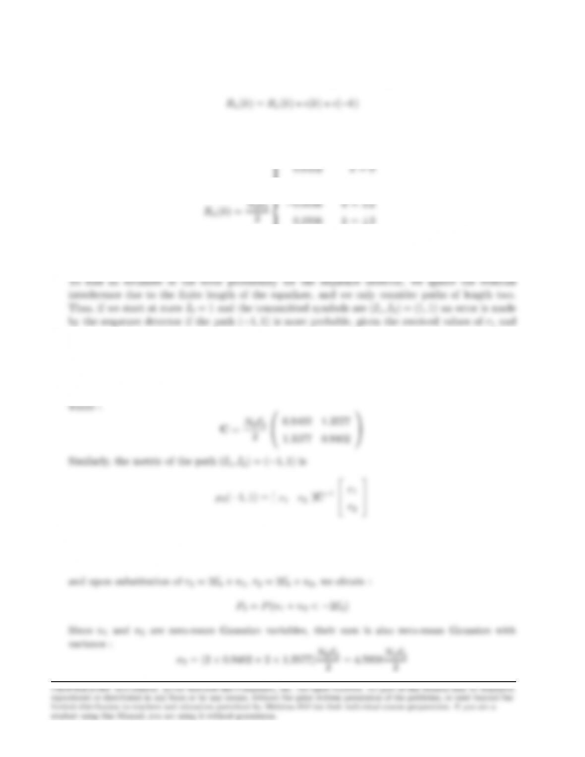
r2. The metric for the path (I1, I2) = (1,1) is :
µ2(1,1) = [ r1−2Ebr2−2Eb]C−1
r1−2Eb
r2−2Eb
r2
Hence, the probability of error is :
P2=P(µ2(−1,1) < µ2(1,1))
39
Problem 9.44
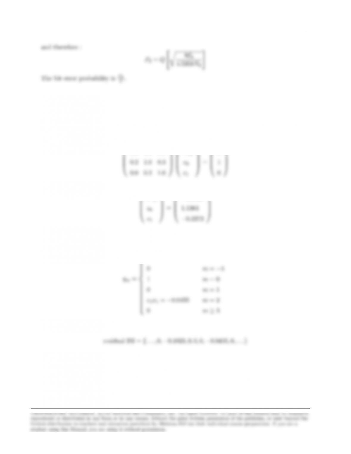
The optimum tap coefficients of the zero-force equalizer can be found by solving the system:
1.0 0.3 0.0
c−1
0
Hence,
c−1
−0.3409
The output of the equalizer is :
0m≤ −3
c−1x−1=−0.1023 m=−2
Hence, the residual ISI sequence is :
Problem 9.45
40
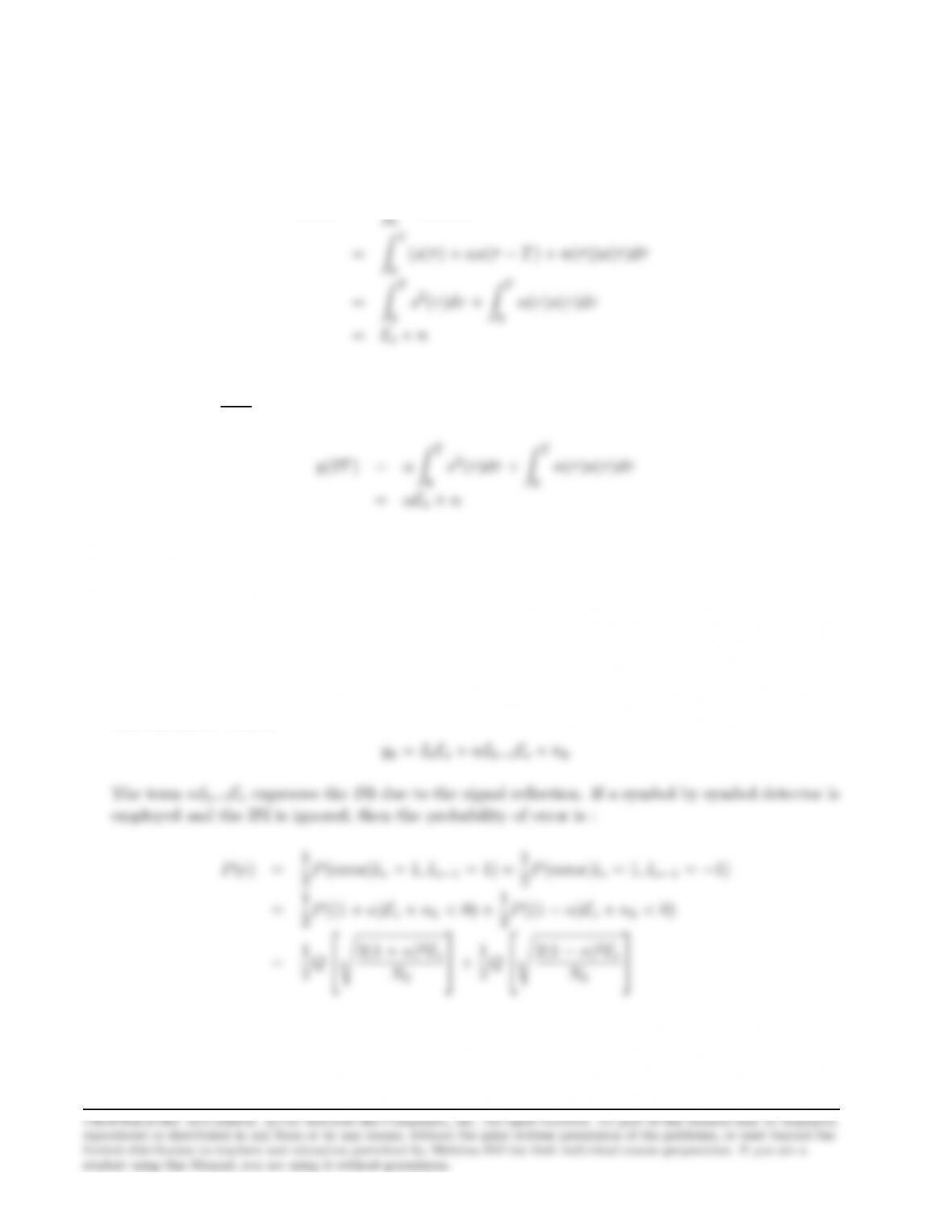
(a) If we assume that the signal pulse has duration T, then the ouput of the matched filter at the
time instant t=Tis :
y(T) = ZT
r(τ)s(τ)dτ
where Esis the energy of the signal pulse and nis a zero-mean Gaussian random variable with
variance σ2
n=N0Es
2. Similarly, the output of the matched filter at t= 2Tis :
(b) If the transmitted sequence is :
x(t) = ∞
X
n=−∞
Ins(t−nT )
with Intaking the values 1,−1 with equal probability, then the output of the demodulator at the
time instant t=kT is
2Q
N0
2Q
N0
(c) To find the error rate performance of the DFE, we assume that the estimation of the parameter
αis correct and that the probability of error at each time instant is the same. Since the transmitted
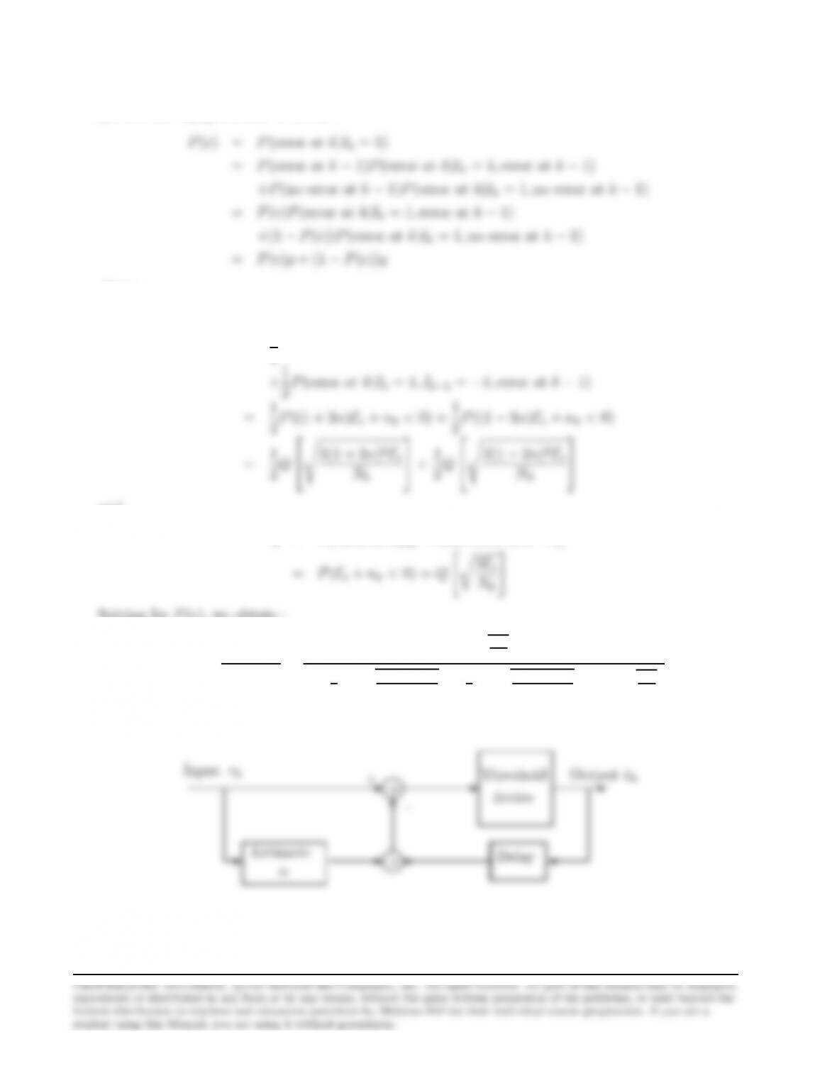
41
symbols are equiprobable, we obtain :
where :
p=P(error at k|Ik= 1,error at k−1)
=1
2P(error at k|Ik= 1, Ik−1= 1,error at k−1)
2Q
N0
2Q
N0
and
q=P(error at k|Ik= 1,no error at k−1)
Solving for P(e), we obtain :
P(e) = q
1−p+q=
Qhq2Es
N0i
1−1
2Qq2(1+2α)2Es
N0−1
2Qq2(1−2α)2Es
N0+Qhq2Es
N0i
A sketch of the detector structure is shown in the next figure.
♥
✻
✲✲✲ +
rk
Input
−
+Output ˆak
device
Threshold
Estimate
Problem 9.46
A discrete time transversal filter equivalent to the cascade of the trasmitting filter gT(t), the channel
c(t), the matched filter at the receicer gR(t) and the sampler, has tap gain coefficients {xm}, where
0.9m= 0
The noise νk, at the output of the sampler, is a zero-mean Gaussian sequence with autocorrelation
If the Z-transform of the sequence {xm},X(z), assumes the factorization :
then the filter 1/F ∗(z−1) can follow the sampler to white the noise sequence νk. In this case the
output of the whitening filter, and input to the MSE equalizer, is the sequence :
k
where nkis zero mean Gaussian with variance σ2. The optimum coefficients of the MSE equalizer,
n=−1
where :
Γ(n−k) =
xn−k+σ2δn,k,|n−k| ≤ 1
0 otherwise
f−k,−1≤k≤0
we obtain the parameters f0and f1as :
±√0.7854
±√0.1146
The parameters f0and f1should have the same sign since f0f1= 0.3. However, the sign itself does
not play any role if the data are differentially encoded. To have a stable inverse system 1/F ∗(z−1),

43
we select f0and f1in such a way that the zero of the system F∗(z−1) = f0+f1zis inside the unit
circle. Thus, we choose f0=√0.1146 and f1=√0.7854 and therefore, the desired system for the
equalizer’s coefficients is
Problem 9.47
(a) The spectrum of the band limited equalized pulse is
X(f) =
1
2WP∞
n=−∞ x(n
2W)e−jπnf
W|f| ≤ W
0 otherwise
1
2Wh2 + 2 cos πf
Wi|f| ≤ W
(b) The following table lists the possible transmitted sequences of length 3 and the corresponding
output of the detector.
-1 -1 -1 -4
-1 -1 1 -2
-1 1 -1 0

44
(c) The transmitting filter GT(f), the receiving filter GR(f) and the equalizer GE(f) satisfy the
condition
GT(f)GR(f)GE(f) = X(f)
the variance of the output noise is :
σ2
ν=σ2Z∞
−∞ |GR(f)GE(f)|2df =σ2Z∞
−∞
X(f)
GT(f)
2
df
4
W|2
π2T2
50W2ZW
01 + cos πf
W2
The value of the previous integral can be found using the formula :
Zeax cosnbxdx
Thus, we obtain :
σ2
ν=8σ2
π2T2
50W2דe2πT50 W−1 1
2πT50
+2πT50 +π1
W2T50
4π2T2
50 + 4 π2
W2!
To find the probability of error using a symbol by symbol detector, we follow the same procedure
as in Section 9.2.3. The results are the same with that obtained from a 3-point PAM constellation

45
But
P(|ym|>1|bm= 0) = 2
√2πσνZ∞
1
e−x2/2σ2
νdx
Problem 9.48
Since the partial response signal has memory length equal to 2, the corresponding trellis has 4
states which we label as (In−1, In). The following figure shows three frames of the trellis. The
✉
✉ ✉
✉
✟✟✟✟
✲
(1,1)
Problem 9.49
(a) X(z) = F(z)F∗(z−1) = 1
2z+ 1 + 1
2z−1.Then, the covariance matrix Γis :
1 + N01/2 0
1/√2

46
The optimum equalizer coefficients are given by :
Copt =Γ−1ξ
(1 + N0)2−1/4−1
1/√2
(b)
det(Γ−λI) = (1 + N0−λ)(1 + N0−λ)2−1
2⇒
and the corresponding eigenvectors are :
−1/√2
1/2
1/2
(c)
0+ 4N2
0+ 2N0+ 3/4
(d)
γ=1−Jmin(1)
Jmin(1) =2N2
0+ 3N0+ 3/4
2N3
0+ 4N2
0+ 1/4
Problem 9.50
For the DFE we have that :
ˆ
Ik=
0
X
j=−K1
cjuk−j+
K2
X
j=1
cjIk−j,and ǫk=Ik−ˆ
Ik
47
The orthogonality principle is simply :
EǫkI∗
k−l= 0,for 1 ≤l≤K2
EIkI∗
k−l=Ehˆ
IkI∗
k−li,1≤l≤K2
Since the information symbols are uncorrelated : E[IkI∗
l] = aδkl,where a=Eh|Ik|2iis a constant
whose value is not needed since it will be present in all terms and thus, cancelled out. In order to
solve the above system, we also need E[uku∗
l], E [Iku∗
l].We have :
E[uku∗
l] = EhPL
n=0 fnIk−n+nkPL
m=0 f∗
mI∗
l−m+n∗
li
Hence, the second equation of the orthogonality principle gives :
EIkI∗
k−l=Ehˆ
IkI∗
k−li,1≤l≤K2⇒
0 = EhP0
j=−K1cjuk−j+PK2
j=1 cjIk−jI∗
k−li⇒
which is the desired equation for the feedback taps. The first equation of the orthogonality principle
will give :
EIku∗
k−l=Ehˆ
Iku∗
k−li,−K1≤l≤0⇒
Substituting the expression for cj,1≤j≤K2,that we found above :
f∗
−l=P0
j=−K1cjPL
m=0 f∗
mfm+l−j+N0δkl−PK2
j=1 P0
m=−K1cmfj−mf∗
j−l,−K1≤l≤0⇒
Problem 9.51
The tap coefficients for the feedback section of the DFE are given by the equation :
ck=−P0
j=−K1cjfk−j, k = 1,2, …, K2
Problem 9.52
(a) The tap coefficients for the feedback section of the DFE are given by the equation : ck=
−P0
But ψlj =P−l
m=0 f∗
mfm+l−j+N0δlj ,so the above system can be written :
1
1
c0
1/√2
(b)
0
X
0+N0

49
Jmin(1) =1 + 4N0
2N0(1 + 2N0)≈1
2N0
(d) For the infinite tap DFE, we have from example 9-5-1 :
Jmin =2N0
1+N0+√(1+N0)2−1≈2N0, N0<< 1
(e) For N0= 0.1,we have :
Jmin(1) = 0.146, γ = 5.83 (7.66 dB)
For N0= 0.01,we have :
Jmin(1) = 0.0193, γ = 51 (17.1 dB)
Problem 9.53
(a) We have that :
1
2T= 900,1+β
2T= 1200 ⇒
(c) The largest interference is caused by the sequence : {1,−1, s, 1,−1,1}or its opposite in sign.
This interference is constructive or destructive depending on the sign of the information symbol s.
(d) The probability of the worst-case interference given above is 1

Problem 9.54
(a)
F(z) = 0.8−0.6z−1⇒
(b)
T
∞
X
n=−∞
T
2
(c) For the linear equalizer base on the mean-square-error criterion we have :
Jmin =T
2πRπ/T
−π/T
N0
1+N0−0.96 cos ωT dω
N0
But : 1
2πZπ
−π
1
1−acos θdθ =1
√1−a2, a2<1
1 + N0
1+N02=N0
(d) For the decision-feedback equalizer :
Jmin =2N0
1 + N0+q(1 + N0)2−(0.96)2

Problem 9.55
(a) Part of the tree structure is shown in the following figure :
❜❜❜❜❜❜❜❜
✧✧✧✧✧✧✧✧
✥✥✥✥✥✥✥
❵❵❵❵❵❵❵
.
I2= 3
I2=−3
I2=−1
❜❜❜❜❜❜❜❜
✥✥✥✥✥✥✥
❵❵❵❵❵❵❵
I2= 3
I2=−3
I2=−1
I2= 1
✧✧✧✧✧✧✧✧
✧✧✧✧✧✧✧
✧
✥✥✥✥✥✥✥
❵❵❵❵❵❵❵
❜❜❜❜❜❜❜
❜
✧✧✧✧✧✧✧
✧
✥✥✥✥✥✥✥
❵❵❵❵❵❵❵
✱
✱
✱
✱
✱
✱
✱
✱
✱
✱
✱
✱
✱
✱
❳❳❳❳❳❳❳❳❳❳❳❳❳❳❳❳❳❳❳
❳
❝❝❝❝❝❝❝❝❝❝❝❝❝❝❝❝❝❝❝
✘✘✘✘✘✘✘✘✘✘✘✘✘✘✘✘✘✘✘
✘
I1= 3
I1= 1
I1=−1
I1=−3
I2= 3
I2= 1
I3= 3
I3=−3
I3=−1
I3= 1
algorithm.
(c) Since, there are four states, the number of surviving sequences is also four.
52
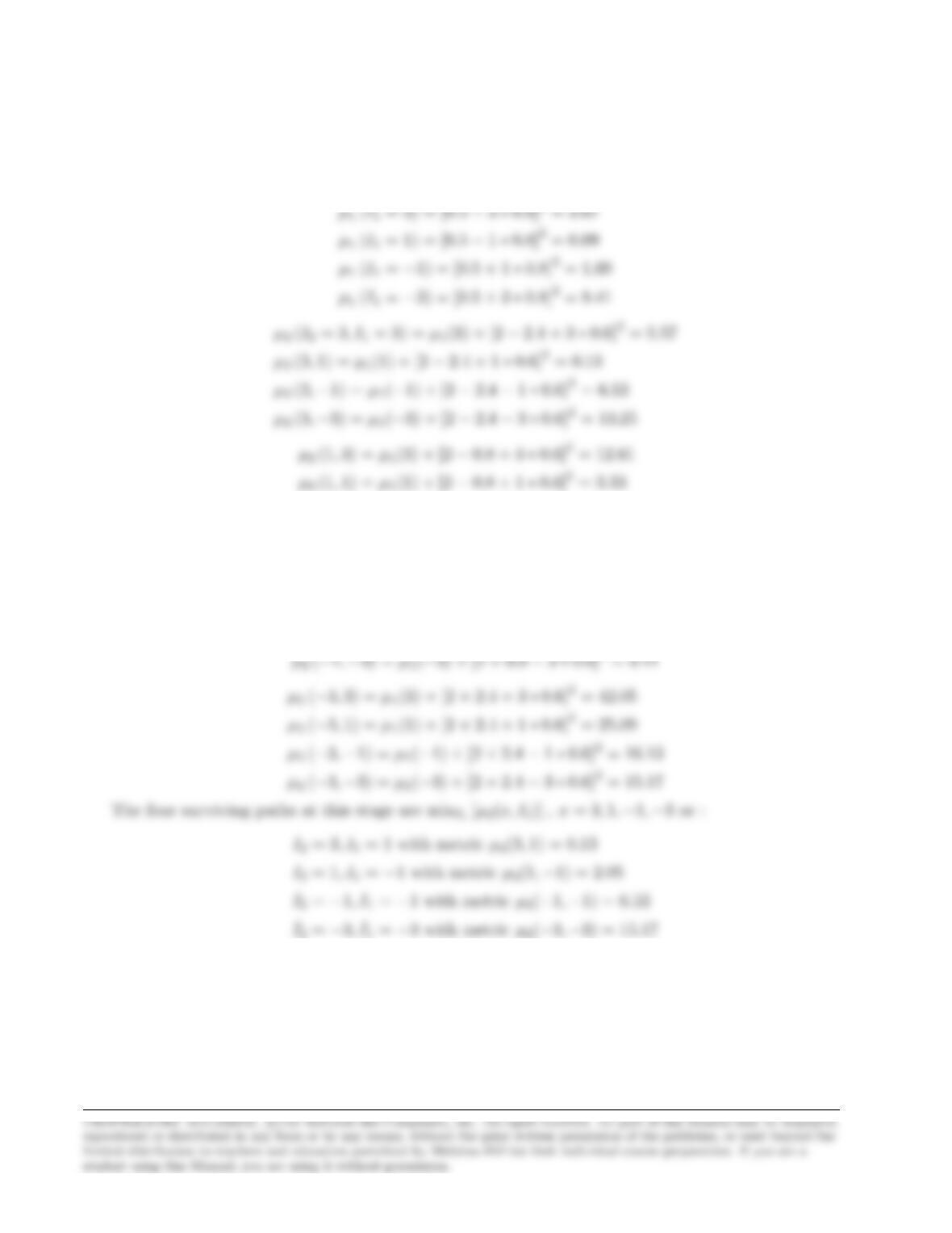
(d) The metrics are
(y1−0.8I1)2, i = 1 and X
i
(yi−0.8Ii+ 0.6Ii−1)2, i ≥2
µ2(1,−1) = µ1(−1) + [2 −0.8−1∗0.6]2= 2.05
µ2(1,−3) = µ1(−3) + [2 −0.8−3∗0.6]2= 8.77
µ2(−1,3) = µ1(3) + [2 + 0.8 + 3 ∗0.6]2= 24.77
µ2(−1,1) = µ1(1) + [2 + 0.8 + 1 ∗0.6]2= 11.65
µ2(−1,−1) = µ1(−1) + [2 + 0.8−1∗0.6]2= 6.53
Now we compute the metrics for the next stage :
µ3(I3= 3, I2= 3, I1= 1) = µ2(3,1) + [−1−2.4 + 1.8]2= 2.69
µ3(3,1,−1) = µ2(1,−1) + [−1−2.4 + 0.6]2= 9.89
µ3(3,−1,−1) = µ2(−1,−1) + [−1−2.4−0.6]2= 22.53
µ3(3,−3,−3) = µ2(−3,−3) + [−1−2.4−1.8]2= 42.21
µ3(−3,1,−1) = µ2(1,−1) + [−1 + 2.4 + 0.6]2= 2.69
µ3(−3,−1,−1) = µ2(−1,−1) + [−1 + 2.4−0.6]2= 7.17
µ3(−3,−3,−3) = µ2(−3,−3) + [−1 + 2.4−1.8]2= 15.33
The four surviving sequences at this stage are minI2,I1[µ3(x, I2, I1)] , x = 3,1,−1,−3 or :
I3= 3, I2= 3, I1= 1 with metric µ3(3,3,1) = 2.69
Problem 9.56
(a)
bk=1
KPK−1
n=0 Enej2πnk/K
=1
KPK−1
n=0 PK−1
l=0 cle−j2πnl/K ej2πnk/K
54
(b)
E(z) = PK−1
k=0 ckz−k
=PK−1
k=0 h1
KPK−1
n=0 Enej2πnk/K iz−k
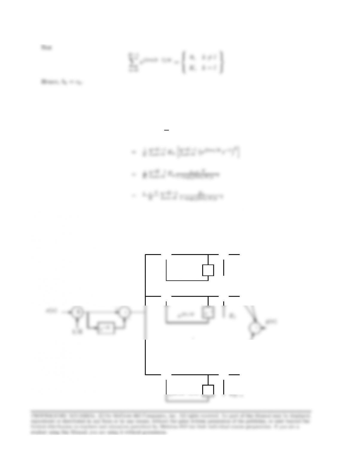
(c) The block diagram is as shown in the following figure :
✒✑
✓✏ ✒✑
✓✏
✲ ✲
❄✻✻
y0(n)
E0
z−1
+X
+
–
✒✑
✓✏ ✒✑
✓✏
✲ ✲
y1(n)
+X
+
✒✑
✓✏ ✒✑
✓✏
✲ ✲
❄✻✻
yK−1(n)
z−1
+X
+
–
❈❈❈❈❈❈❈❈❈❈❈❈
❏❏❏❏
✂✂✂✂✂✂✂
Comb.Filter
–
.
.
.
Parallel Bank of Single −Pole Filters