21
The output of the matched filter is sampled at t=Tand the samples are passed to the detector.
The detector is a simple threshold device that decides if a binary 1 or 0 was transmitted depending
on the sign of the input samples. The following figure shows a block diagram of the optimum
bandpass coherent demodulator.
✂
.
.
.
.
.
.
.
.
.
.
.
.
.
❘❅
❅✲✲✲
device)
(Threshold
t=T
r(t)
gR(t)
matched filter
Problem 9.22
(a) The power spectral density of X(t) is given by (see (4-4-12))
Φx(f) = 1
TΦa(f)|GT(f)|2
The Fourier transform of g(t) is
GT(f) = F[g(t)] = AT sin πfT
πfT e−jπf T
(b) If g1(t) is used instead of g(t) and the symbol interval is T, then
(c) If we precode the input sequence as bn=an+αan−3, then
1 + α2m= 0

22
To obtain a null at f=1
3
(c) The answer to this question is no. This is because Φb(f) is an analytic function and unless it
Problem 9.23
The roll-off factor βis related to the bandwidth by the expression 1+β
T= 2W, or equivalently
R(1 + β) = 2W. The following table shows the symbol rate for the various values of the excess
Problem 9.24
The following table shows the precoded sequence, the transmitted amplitude levels, the received
signal levels and the decoded sequence, when the data sequence 10010110010 modulates a duobinary
transmitting filter.
Data seq. Dn: 1 0 0 1 0 1 1 0 0 1 0
Problem 9.25

23
The following table shows the precoded sequence, the transmitted amplitude levels, the received
signal levels and the decoded sequence, when the data sequence 10010110010 modulates a modified
duobinary transmitting filter.
Data seq. Dn: 1 0 0 1 0 1 1 0 0 1 0
Precoded seq. Pn: 0 0 1 0 1 1 1 0 0 0 0 1 0
Problem 9.26
Let X(z) denote the Z-transform of the sequence xn, that is
X(z) = X
n
xnz−n
Then the precoding operation can be described as
P(z) = D(z)
X(z)mod −M
Problem 9.27
24
(a) The frequency response of the RC filter is
C(f) =
1
j2πRCf
R+1
j2πRCf
=1
1 + j2πRCf
The amplitude and the phase spectrum of the filter are :
|C(f)|=1
1 + 4π2(RC)2f21
2
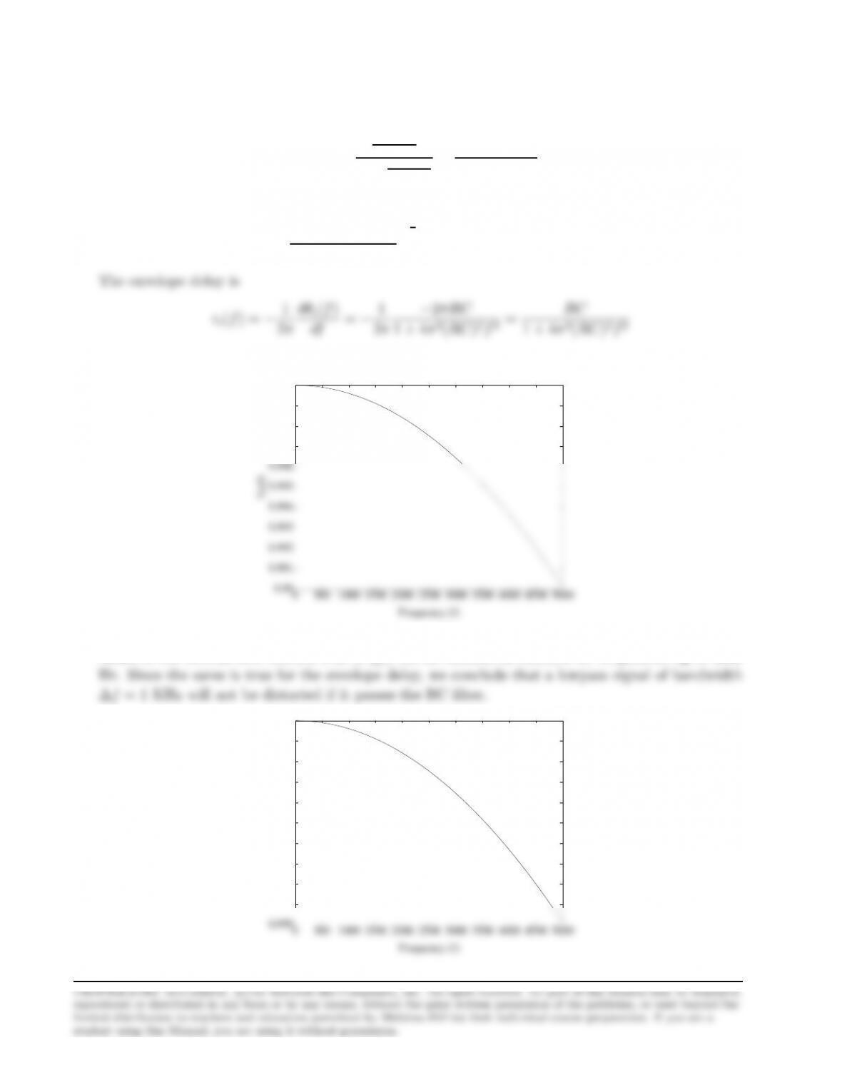
, θc(f) = arctan(−2πRCf)
A plot of τ(f) with RC = 10−6is shown in the next figure :
9.99
9.991
9.992
9.993
9.994
9.995
9.996
9.997
9.998
9.999
10x10-7
0 500 1000 1500 2000 2500 3000 3500 4000 4500 5000
Frequency (f)
Tc(f)
(b) The following figure is a plot of the amplitude characteristics of the RC filter, |C(f)|. The
values of the vertical axis indicate that |C(f)|can be considered constant for frequencies up to 2000
Problem 9.28
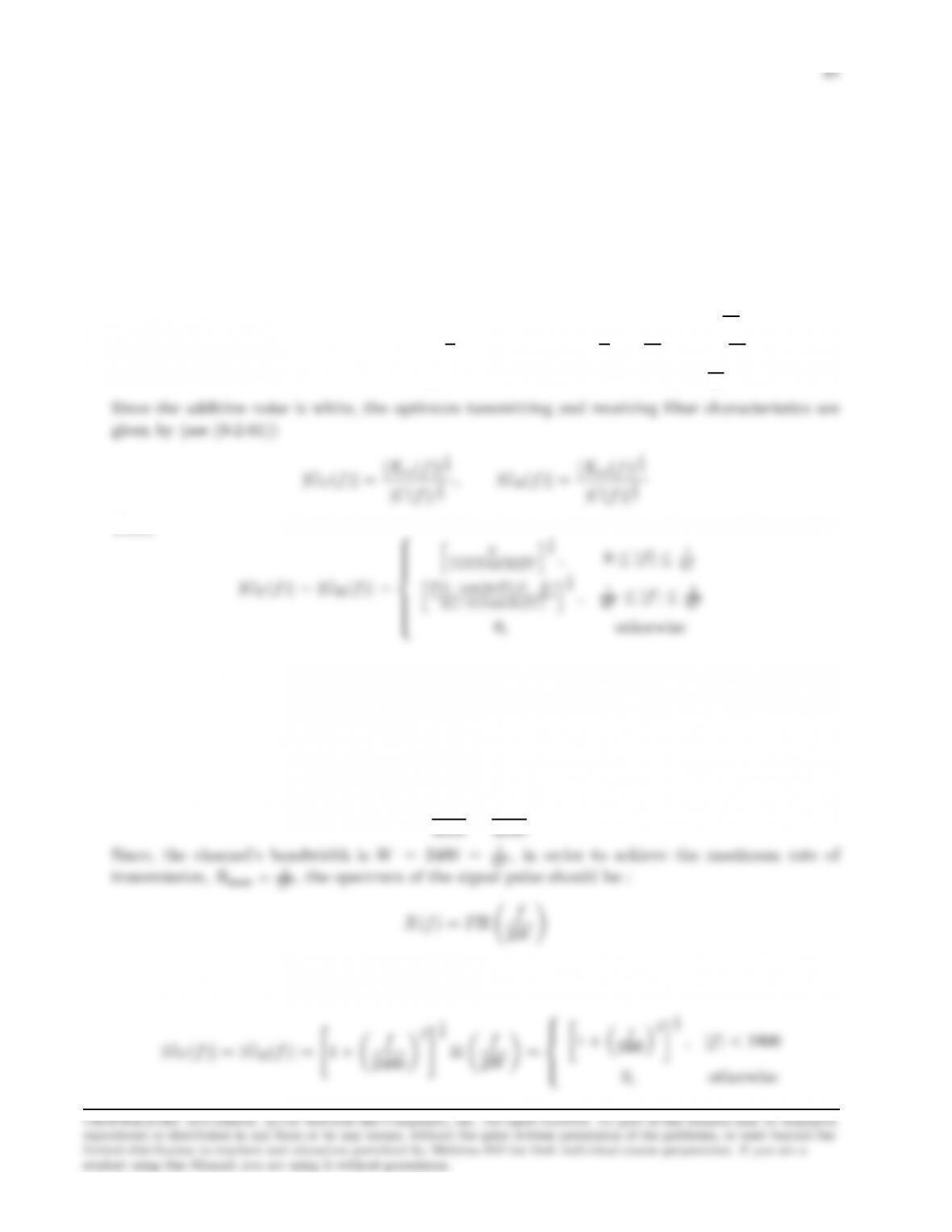
Let GT(f) and GR(f) be the frequency response of the transmitting and receiving filter. Then, the
condition for zero ISI implies
GT(f)C(f)GR(f) = Xrc(f) =
T, 0≤ |f| ≤ 1
4T
T
2[1 + cos(2πT (|f| − 1
T)],1
4T≤ |f| ≤ 3
4T
0,|f|>3
4T
Thus,
hT
1+0.3 cos 2πf T i1
2,0≤ |f| ≤ 1
4T
hT(1+cos(2πT (|f|− 1
1
Problem 9.29
A 4-PAM modulation can accomodate k= 2 bits per transmitted symbol. Thus, the symbol
interval duration is :
T=k
Then, the magnitude frequency response of the optimum transmitting and receiving filter is (see
(9-2-81))
4
1 + f
2400 21
4
,|f|<2400

Problem 9.30
We already know that
σ2
v=Z∞
−∞
Φnn(f)|GR(f)|2df
From these
σ2
v
d2=1
PavTZW
−W
Φnn(f)|GR(f)|2df ZW
−W
|Xrc(f)|2
|GR(f)|2|C(f)|2df (9.0.4)
The optimum |GR(f)|can be found by applying the Cauchy-Schwartz inequality
where |U1(f)|,|U2(f)|are defined as
|U1(f)|=|pΦnn(f)||GR(f)|
|U2(f)|=|Xrc(f)|
|GR(f)||C(f)|

Problem 9.31
In the case where the channel distortion is fully precompensated at the transmitter, the loss of
SNR is given by
10 log L1,with L1=ZW
−W
Xrc(f)
|C(f)|2
whereas in the case of the equally split filters, the loss of SNR is given by
10 log[L2]2,with L2=ZW
−W
Xrc(f)
|C(f)|
Assuming that 1/T =W, so that we have a raised cosine characteristic with β= 0, we have
Hence, the loss for the first type of filters is 10 log L1= 1.89 dB.
In a similar way,
1
[1+cos πf
W]
Problem 9.32
Suppose that am= +1 is the transmitted signal. Then the probability of error will be :
Pe|1=P(ym<0|am= +1)
=P(1 + nm+im<0)
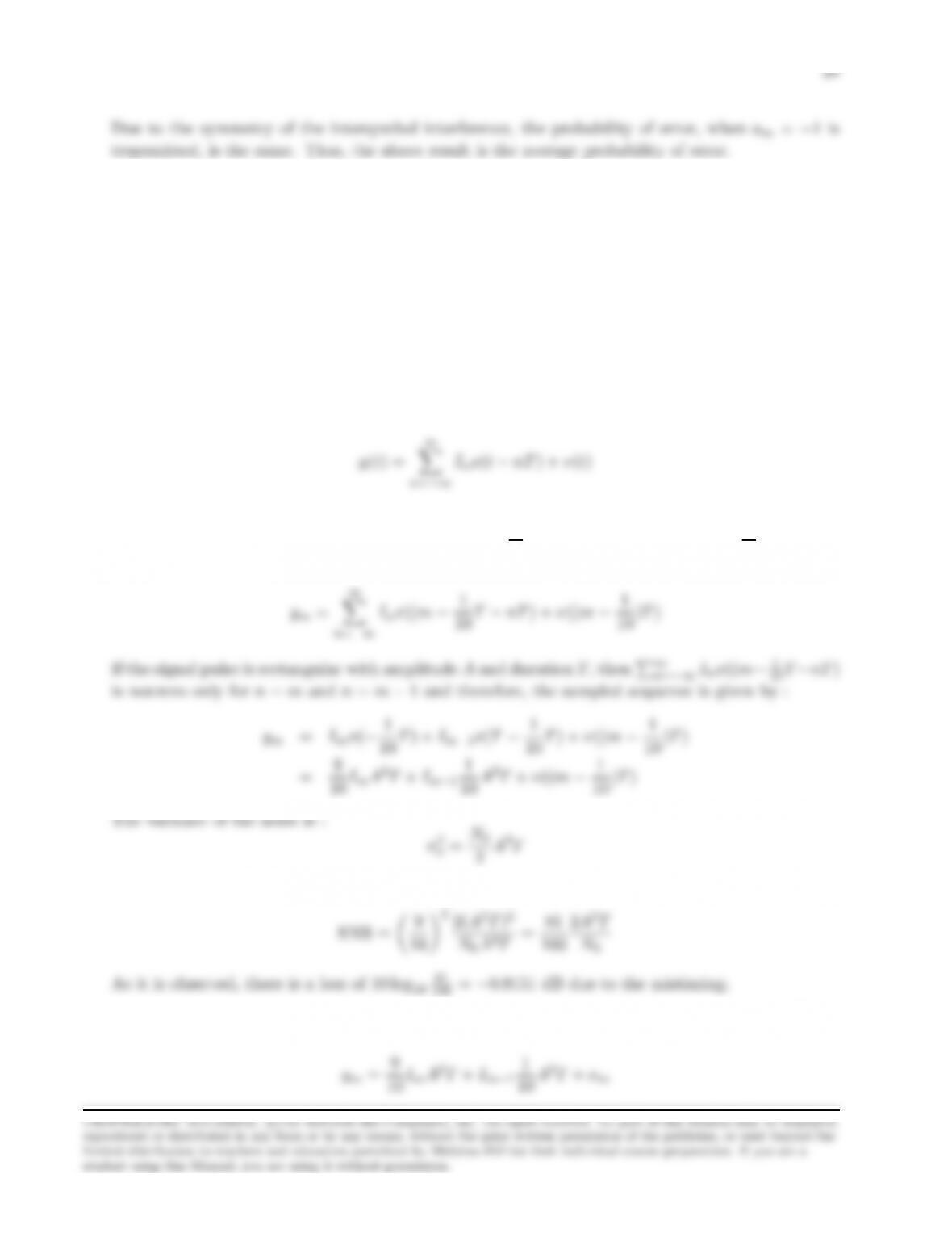
Problem 9.33
(a) If the transmitted signal is :
r(t) = ∞
X
n=−∞
Inh(t−nT ) + n(t)
then the output of the receiving filter is :
X
n=−∞
where x(t) = h(t)⋆ h(t) and ν(t) = n(t)⋆ h(t). If the sampling time is off by 10%, then the samples
at the output of the correlator are taken at t= (m±1
10 )T. Assuming that t= (m−1
10 )Twithout
loss of generality, then the sampled sequence is :
X
and therefore, the SNR is :
2A2T
(b) Recall from part (a) that the sampled sequence is
1

29
The term Im−1A2T
10 expresses the ISI introduced to the system. If Im= 1 is transmitted, then the
probability of error is
P(e|Im= 1) = 1
2Q
N0
2Q
1022A2T
N0
Since the symbols of the binary PAM system are equiprobable the previous derived expression is
the probability of error when a symbol by symbol detector is employed. Comparing this with the
2Q
1022A2T
N0
2Q
N0
Problem 9.34
(a) Taking the inverse Fourier transform of H(f), we obtain :
h(t) = F−1[H(f)] = δ(t) + α
2δ(t−t0) + α
2δ(t+t0)
(b) If the signal s(t) is used to modulate the sequence {In}, then the transmitted signal is :
u(t) = ∞
X
n=−∞
Ins(t−nT )
w(t1) = ∞
X
n=−∞
InZ∞
−∞
s(τ−nT )s(τ−t1)dτ
+α
2
∞
X
InZ∞
−∞
s(τ−t0−nT )s(τ−t1)dτ
∞
X
2
n=−∞
2
n=−∞
(c) With t0=Tand k=nin the previous equation, we obtain :
wk=Ikx0+X
n6=k
Inxk−n
Problem 9.35
(a) Each segment of the wire-line can be considered as a bandpass filter with bandwidth W= 1200
Hz. Thus, the highest bit rate that can be transmitted without ISI by means of binary PAM is :

31
(b) The probability of error for binary PAM trasmission is :
P2=Q“r2Eb
N0#
N0
N0
(c) The received power PRis related to the desired SNR per bit through the relation :
PR
N0
=1
TEb
N0
=REb
N0
Problem 9.36
xn=Z∞
−∞
h(t+nT )h∗(t)dt
vk=Z∞
z(t)h∗(t−kT )dt
Problem 9.37
In the case of duobinary signaling, the output of the matched filter is :
x(t) = sinc(2W t) + sinc(2W t −1)
n
Problem 9.38
(a) The output of the matched filter demodulator is :
y(t) = ∞
X
k=−∞
IkZ∞
−∞
gT(τ−kTb)gR(t−τ)dτ +ν(t)
=∞
X
k=−∞
Ikx(t−kTb) + ν(t)
Hence,
y(mTb) = ∞
X
k=−∞
Ikx(mTb−kTb) + v(mTb)

33
(b) In the next figure we show one trellis stage for the ML sequence detector. Since there is
postcursor ISI, we delay the received signal, used by the ML decoder to form the metrics, by one
sample. Thus, the states of the trellis correspond to the sequence (Im−1, Im), and the transition
✉
✉
✏✏✏✏✏✏✏
◗
-1
1 1
Problem 9.39
(a) The output of the matched filter at the time instant mT is :
ym=X
k
Imxk−m+νm=Im+1
4Im−1+νm
The autocorrelation function of the noise samples νmis
If a symbol by symbol detector is employed and we assume that the symbols Im=Im−1=√Eb
have been transmitted, then the probability of error P(e|Im=Im−1=√Eb) is :
P(e|Im=Im−1=pEb) = P(ym<0|Im=Im−1=pEb)
4√Eb
m
N0dνm
If however Im−1=−√Eb, then :
P(e|Im=pEb, Im−1=−pEb) = P(3
4pEb+νm<0) = Q“3
4r2Eb
N0#
34
Since the two symbols √Eb,−√Ebare used with equal probability, we conclude that :
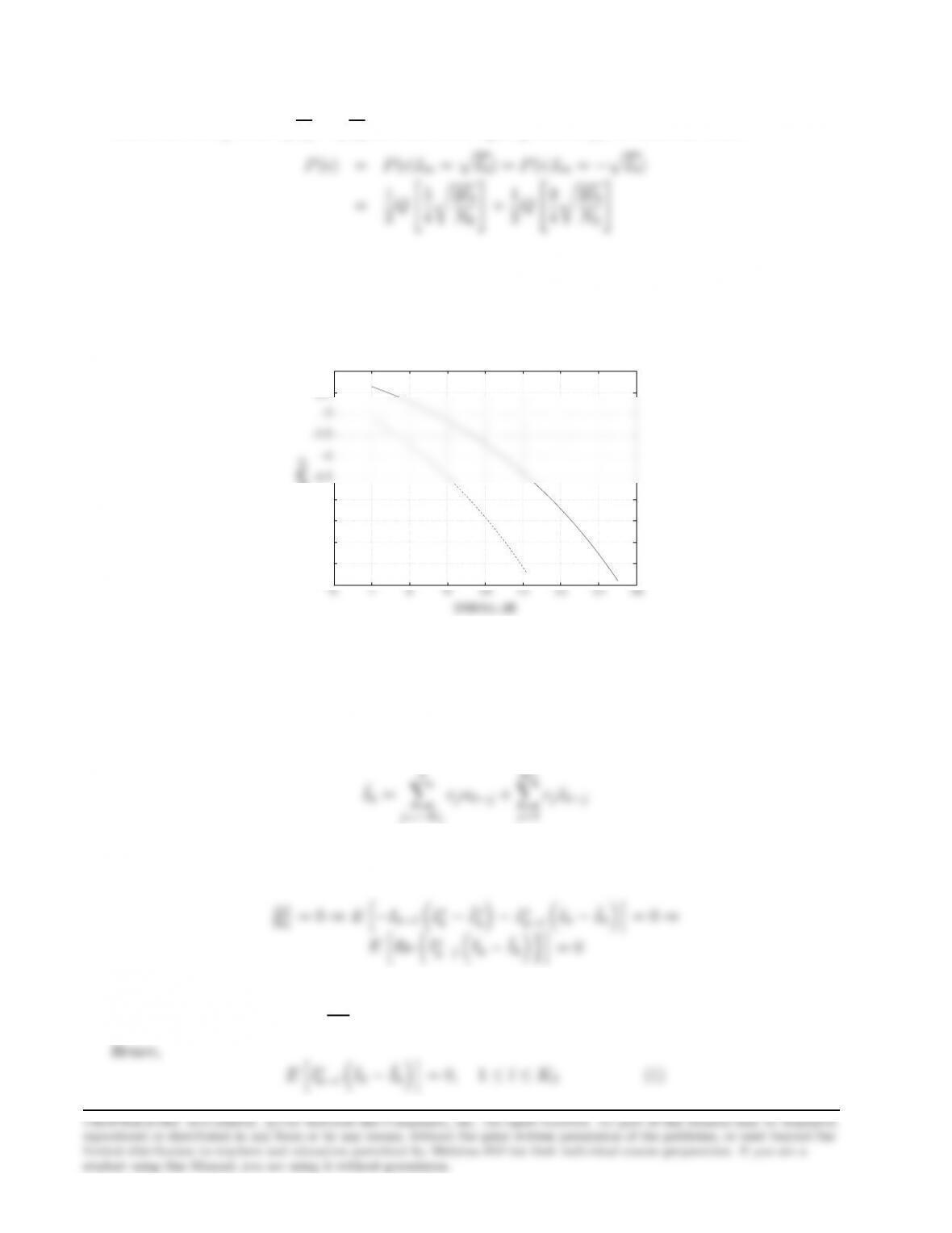
(b) In the next figure we plot the error probability obtained in part (a) (log10(P(e))) vs. the SNR
per bit and the error probability for the case of no ISI. As it observed from the figure, the relative
difference in SNR of the error probability of 10−6is 2 dB.
-7
-6.5
-6
-5.5
-5
-4.5
-4
-3.5
-3
-2.5
-2
log(P(e)
Problem 9.40
For the DFE we have that :
0
X
j=−K1
K2
X
j=1
We want to minimize J=EIk−ˆ
Ik
2.Taking the derivative of J, with respect to the real and
imaginary parts of cl=al+jbl,1≤l≤K2,we obtain :
k−lIk−ˆ
and similarly : ∂J
∂bl
= 0 ⇒EhIm nI∗
k−lIk−ˆ
Ikoi= 0
35
Since the information symbols are uncorrelated : E[IkI∗
l] = δkl.We also have :
E[Iku∗
l] = EhIkPL
m=0 f∗
mI∗
l−m+n∗
li
Hence, equation (1) gives :
EIkI∗
k−l=Ehˆ
IkI∗
k−li,1≤l≤K2⇒
which is the desired equation for the feedback taps.
Problem 9.41
(a) The equivalent discrete-time impulse response of the channel is :
h(t) =
1
X
n=−1
hnδ(t−nT ) = 0.3δ(t+T) + 0.9δ(t) + 0.3δ(t−T)
n=−1
which in matrix notation is written as :
0.9 0.3 0.
c−1
0
The coefficients of the zero-force equalizer can be found by solving the previous matrix equation.
Thus,
c−1
−0.4762
36
(b) The values of qmfor m=±2,±3 are given by
q2=
1
X
n=−1
cnh2−n=c1h1=−0.1429
1
X
n=−1
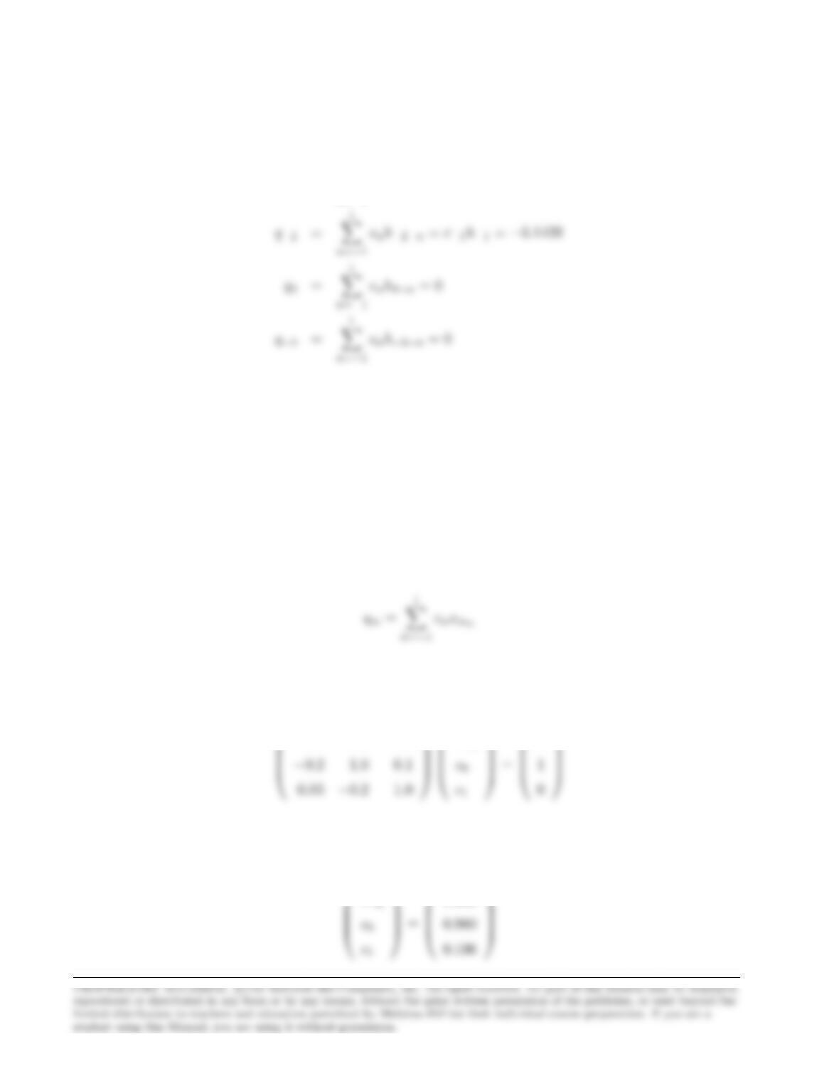
Problem 9.42
(a) The output of the zero-force equalizer is :
1
X
n=−1
With q0= 1 and qm= 0 for m6= 0, we obtain the system :
1.0 0.1−0.5
c−1
0
Solving the previous system in terms of the equalizer’s coefficients, we obtain :
c−1
0.000
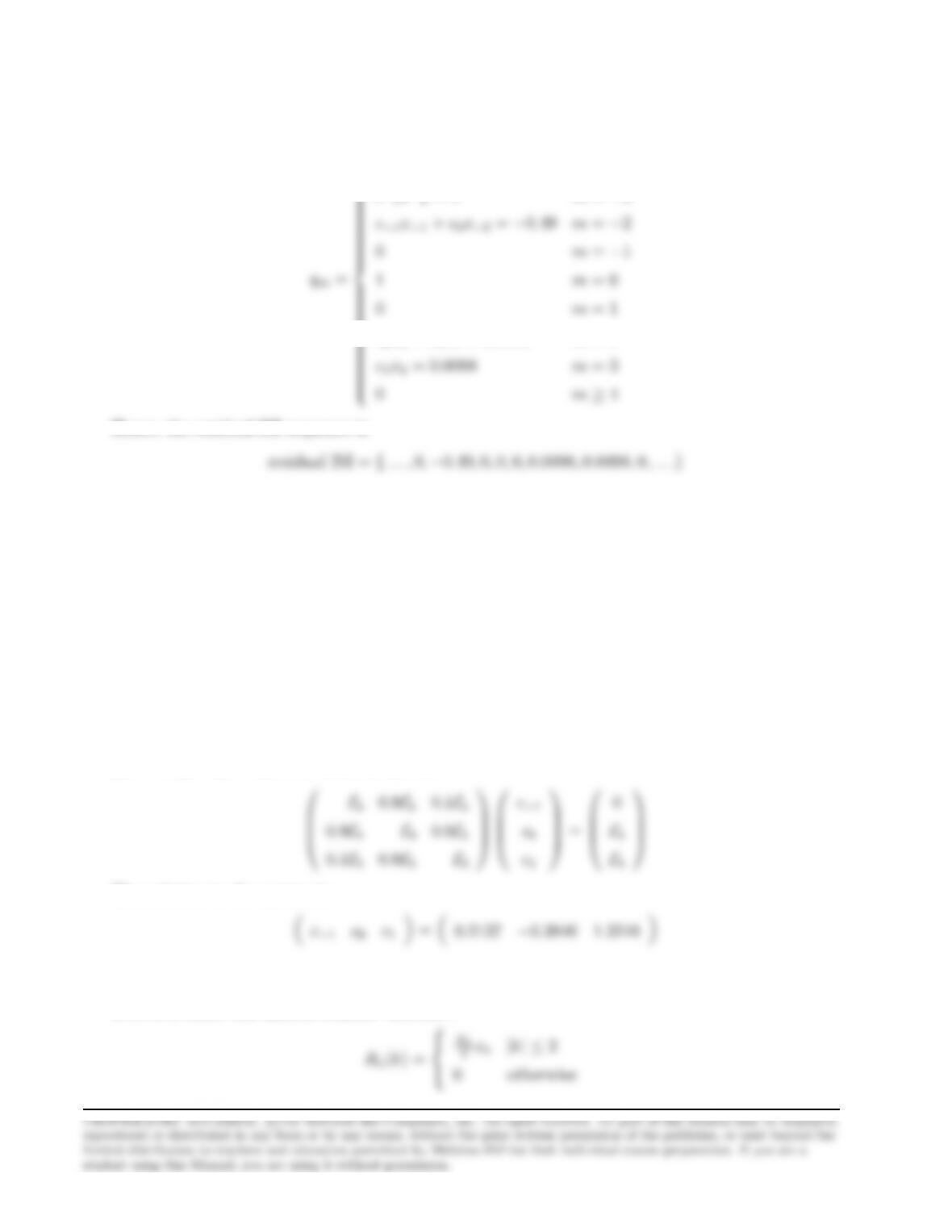
37
(b) The output of the equalizer is :
0m≤ −4
c0x2+x1c1= 0.0098 m= 2
Hence, the residual ISI sequence is
and its span is 6 symbols.
Problem 9.43
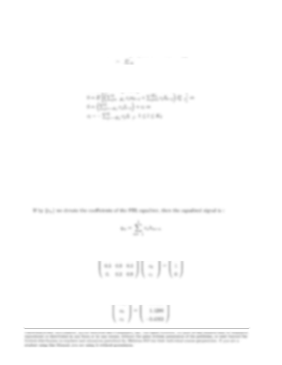
(a) If {cn}denote the coefficients of the zero-force equalizer and {qm}is the sequence of the
equalizer’s output samples, then :
qm=
1
X
n=−1
cnxm−n
where {xk}is the noise free response of the matched filter demodulator sampled at t=kT . With
q−1= 0, q0=q1=Eb, we obtain the system :
0.1Eb0.9EbEb
c1
Eb
The solution to the system is :
(b) The set of noise variables {νk}at the output of the sampler is a gaussian distributed sequence
with zero-mean and autocorrelation function :
N0
2xk|k| ≤ 2