
Solutions Manual
for
Digital Communications, 5th Edition
(Chapter 9) 1
Prepared by
Kostas Stamatiou
January 15, 2008
Problem 9.1
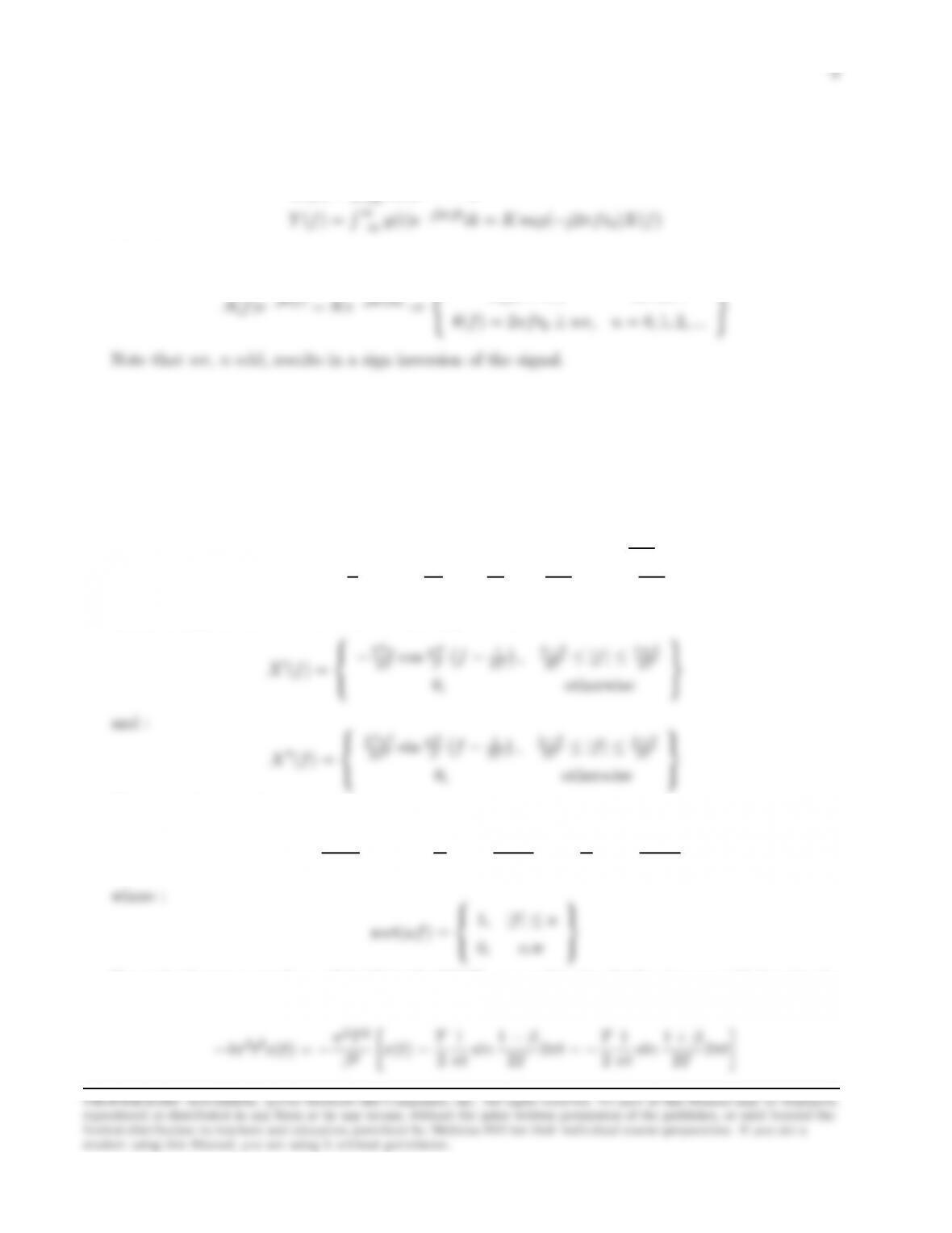
We want y(t) = Kx(t−t0).Then :
X(f) = R∞
Therefore :
A(f) = K, for all f
Problem 9.2
(a) Since cos(a+π/2) = −sin(a),we can write :
X(f) =
T, 0≤ |f| ≤ 1−β
2T
T
2h1−sin πT
βf−1
2Ti,1−β
2T≤ |f| ≤ 1+β
2T
Then, taking the first two derivatives with respect to f:
−T2π
2βcos πT
βf−1
2T,1−β
2T≤ |f| ≤ 1+β
2T
0,otherwise
Therefore the second derivative can be expressed as :
X′′(f) = −π2T2
β2X(f)−T
2rect 1−β
2Tf−T
2rect 1 + β
2Tf
0,o.w
Since the Fourier transform of dx/dt is j2πfX(f), we exploit the duality between (f, t),take the
inverse Fourier transform of X′′(f) and obtain :
1
1

x(t) = 1
1−4β2t2/T h1
2πt/T sin 1−β
2T2πt + sin 1+β
2T2πti
(b) When β= 1, X(f) is non-zero in |f| ≤ 1/T, and :
The Hilbert transform is :
ˆ
X(f) =
−jT
2(1 + cos πT f),0≤f≤1/T
jT
2(1 + cos πT f ),−1/T ≤f≤0
−1/T ˆ
0ˆ
Direct substitution for ˆ
X(f) yields the result :
ˆx(t) = T
πt sin 2πt/T −4t2/T 2
1−4t2/T 2
Note that ˆx(t) is an odd function of t.
(d) The single-sideband signal is :
Problem 9.3
4
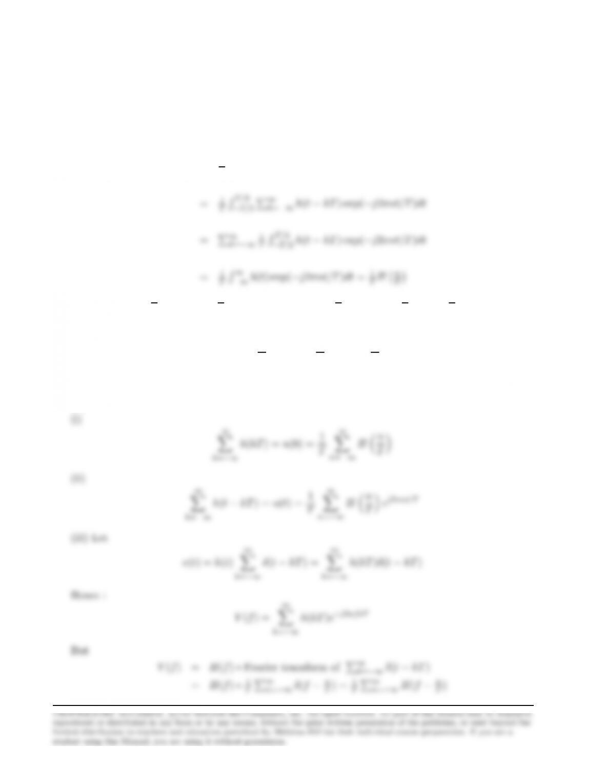
(a) Pkh(t−kT ) = u(t) is a periodic signal with period T. Hence, u(t) can be expanded in the
Fourier series :
u(t) = ∞
X
n=−∞
unej2πnt/T
where :
un=1
TRT/2
−T/2u(t) exp(−j2πnt/T )dt
Then : u(t) = 1
TP∞
n=−∞ Hn
Tej2πnt/T ⇒U(f) = 1
TP∞
n=−∞ Hn
Tδf−n
T.Since x(t) =
u(t)g(t),it follows that X(f) = U(t)∗G(f).Hence :
X(f) = 1
T
∞
X
n=−∞
Hn
TGf−n
T
(b)
5
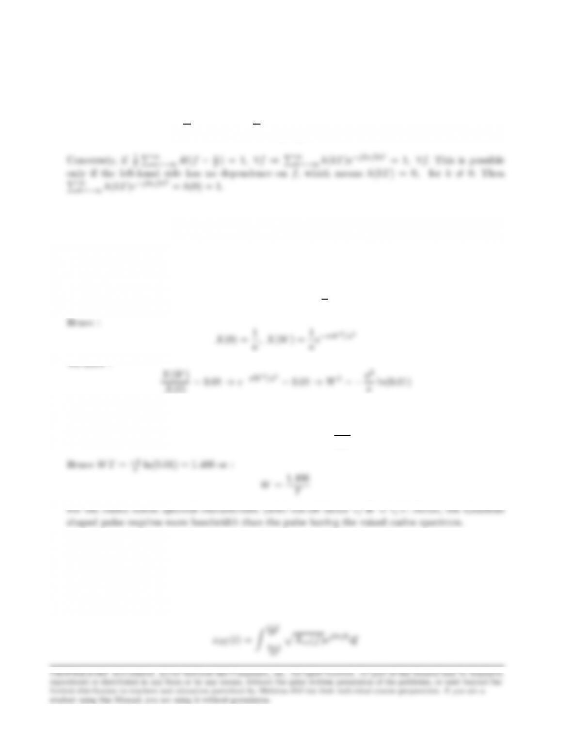
(c) The criterion for no intersymbol interference is {h(kT ) = 0, k 6= 0 and h(0) = 1}.If the above
condition holds, then from (iii) above we have :
1
T
∞
X
n=−∞
H(f−n
T) = ∞
X
k=−∞
h(kT )e−j2πf kT = 1
Problem 9.4
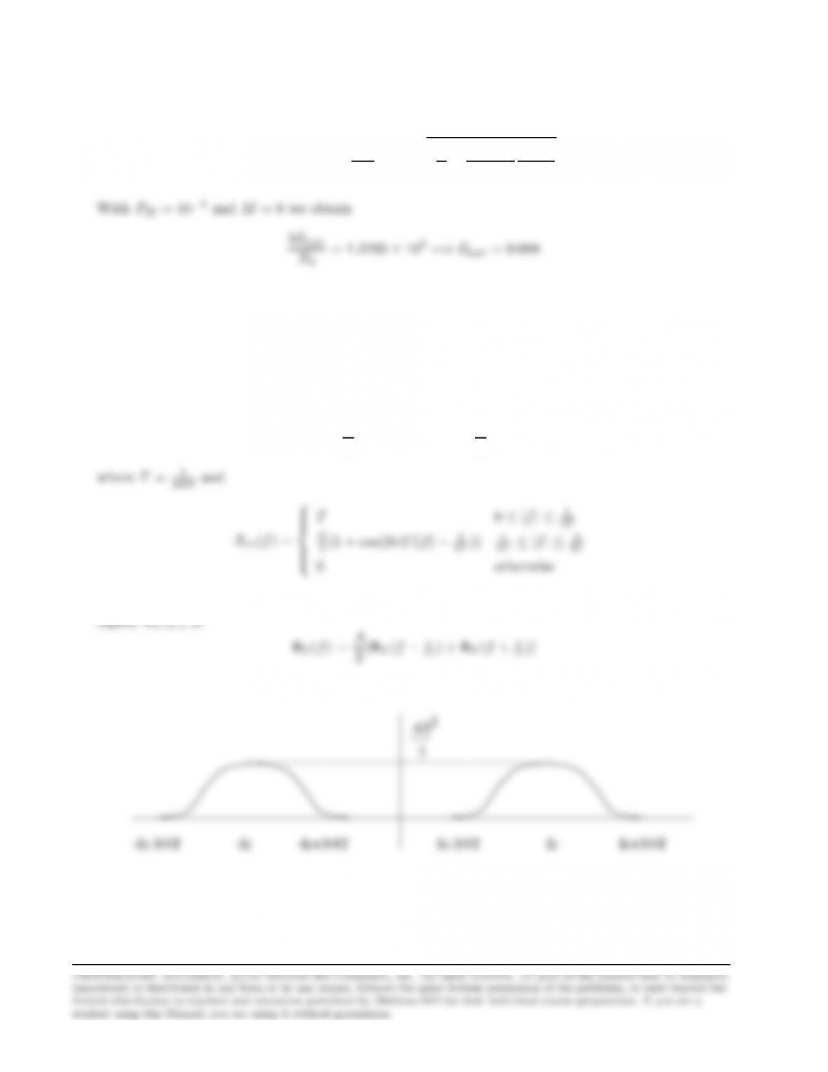
x(t) = e−πa2t2⇒X(f) = 1
ae−πf2/a2
But due to the condition for the reduced ISI :
x(T) = e−πa2T2= 0.01 ⇒T2=−1
πa2ln(0.01)
Problem 9.5
The impulse response of a square-root raised cosine filter is given by
2T
6
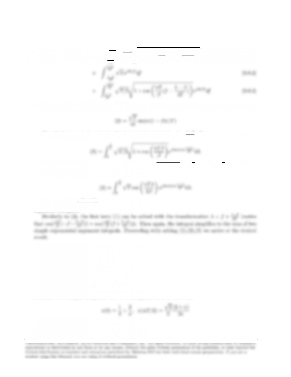
where Xrc(f) is given by (9.2-26). Splitting the integral in three parts we obtain
xST (t) = Z−1−β
2T
−1+β
β(−f−1−β
2T)ej2πftdf (9.0.1)
2T
√T ej2πf tdf (9.0.2)
2TpT/2s1 + cos πT
The second term (2) gives immediately
The third term can be solved with the transformation λ=f−1−β
2T. Then
T
0pT/2s1 + cos πT λ
βej2πt(λ+1+β
Using the relationship 1 + cos 2A= 2 cos2A⇒√1 + cos 2A=√2|cos A|=√2 cos A, we can
rewrite the above expression as
T
0
√Tcos πT λ
2βej2πt(λ+1+β
Since cos A=ejA+e−jA
2, the above integral simplifies to the sum of two simple exponential
argument intregrals.
Problem 9.6
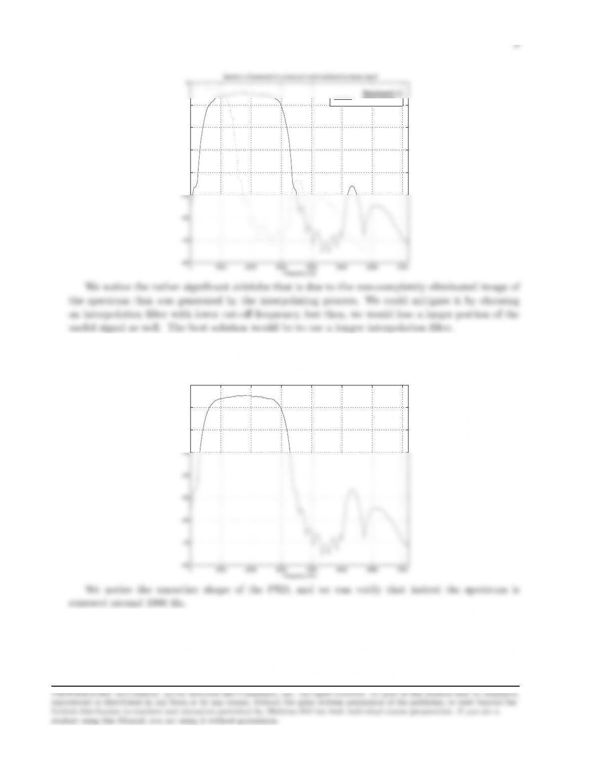
(a)(b) In order to calculate the frequency response based on the impulse response, we need the
values of the impulse response at t= 0,±T/2, which are not given directly by the expression of
Problem 9.5. Using L’Hospital’s rule it is straightforward to show that:
(2 + π)
Then, the frequency response of the filters with N= 10,15,20 compared to the frequency
response of the ideal square-root raised cosine filter are depicted in the following figure.

7
0 0.1 0.2 0.3 0.4 0.5 0.6 0.7 0.8 0.9 1
−70
−60
−50
−40
−30
−20
−10
0
10
Frequency response of truncated SQRT Raised Cosine filters
t/T
dB
Ideal
N=10
N=15
N=20
As we see, there is no significant difference in the passband area of the filters, but the realizable,
truncated filters do have spectral sidelobes outside their (1 + β)/T nominal bandwidth. Still,
Problem 9.7
(a),(b) Given a mathematical package like MATLAB, the implementation in software of the
digital modulator of Fig P9.7 is relatively straightforward. One comment is that the interpolating
filters should have a nominal passband of [−π/3, π/3], since the interpolation factor applied to the
samples at the output of the shaping filter is 3. We chose our interpolation filters (designed with
9
(a) The alternative expression for s(t) can be rewritten as
s(t) ? = Re nPnI′
nQ(t−nT )o
=Re PnInej2πfcnT g(t−nT )[cos 2πfc(t−nT ) + jsin(2πfc(t−nT )]
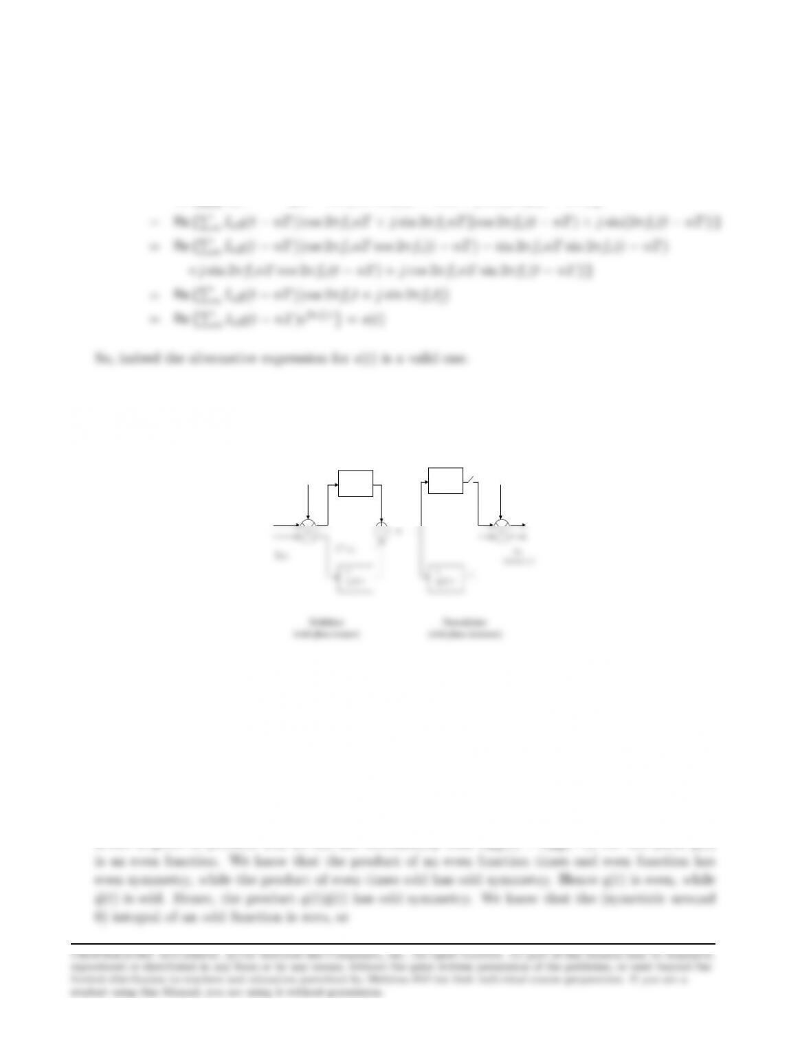
(b)
I
nr
I
ni
e
j2pfnT
I’
nr
I’
ni
–
q(t)
q(t)
^
Modulator
(with phase rotator)
e
-j2pfnT
q(t)
q(t)
^
Demodulator
(with phase
derotator
)
To
Detector
Problem 9.9
(a) From the impulse response of the pulse having a square-root raised cosine characteristic,
which is given in problem 9.5, we can see immediately that xSQ(t) = xSQ(−t), i.e. the pulse g(t)
10
Z∞
−∞
q(t)ˆq(t)dt =Z(1+β)/2T
−(1+β)/2T
q(t)ˆq(t)dt = 0
Problem 9.10
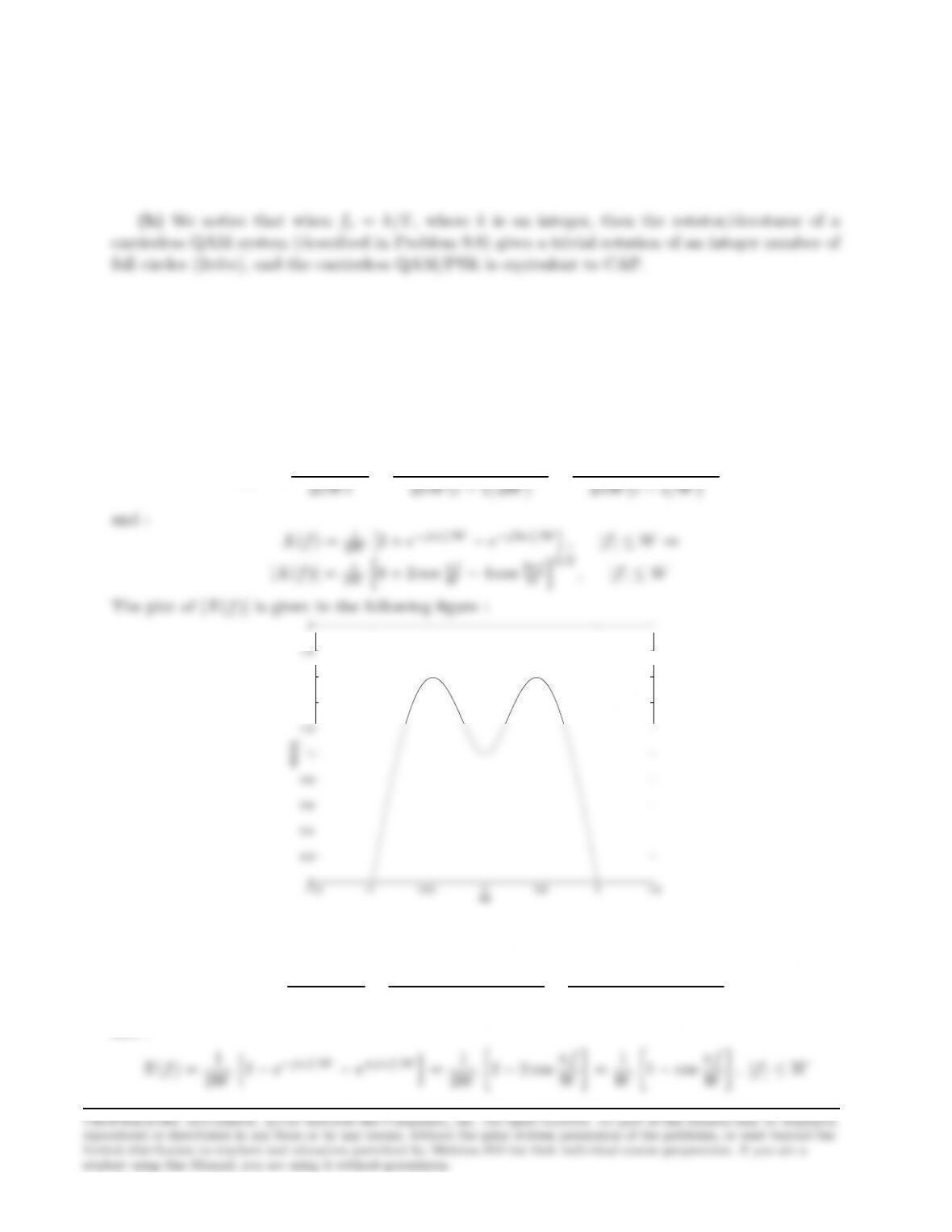
(a)
(i) x0= 2, x1= 1, x2=−1,otherwise xn= 0.Then :
x(t) = 2sin(2πW t)
11
The plot of |X(f)|is given in the following figure :
−1.5 −1 −0.5 0 0.5 1 1.5
0
0.5
1
1.5
2
2.5
fW
W|X(f)|
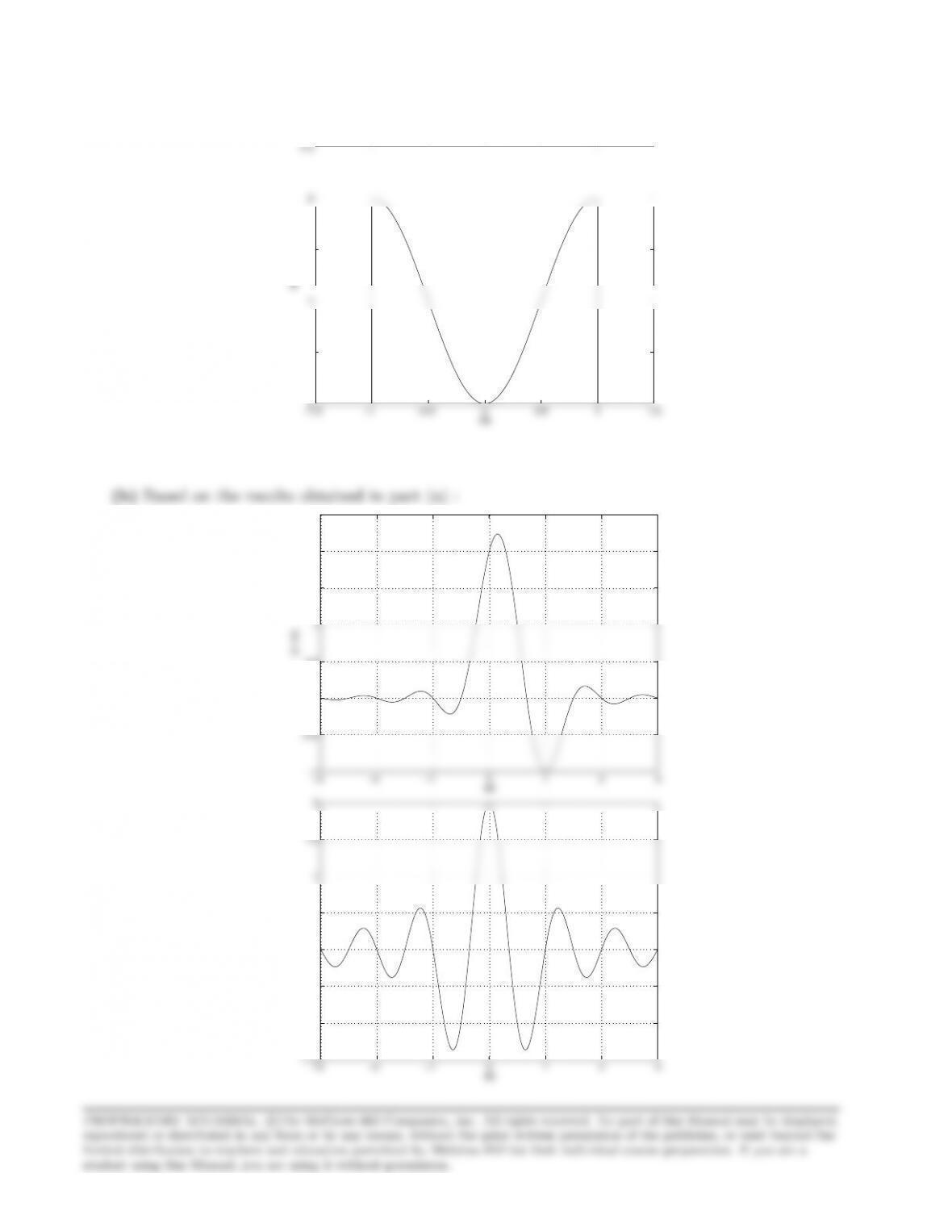
(b) Based on the results obtained in part (a) :
−3 −2 −1 0 1 2 3
−1
−0.5
0
0.5
1
1.5
2
2.5
tW
(i): x(t)
−0.5
0
0.5
1
1.5
2
(ii): x(t)
12
(c) The possible received levels at the receiver are given by :
(i)
Bn= 2In+In−1−In−2
where Im=±1.Hence :
P(Bn= 0) = 1/4
(ii)
Bn= 2In−In−1−In+1
where Im=±1.Hence :
P(Bn= 0) = 1/4
Problem 9.11
The bandwidth of the bandpass channel is W= 4 KHz. Hence, the rate of transmission should be
less or equal to 4000 symbols/sec. If a 8-QAM constellation is employed, then the required symbol
rate is R= 9600/3 = 3200. If a signal pulse with raised cosine spectrum is used for shaping, the
maximum allowable roll-off factor is determined by :
1600(1 + β) = 2000
13
where :
P√M= 2 1−1
√MQ“s3Eav
(M−1)N0#
Note that if the desired spectral characteristic Xrc(f) is split evenly between the transmitting and
receiving filter, then the energy of the transmitting pulse is :
mitted power is :
Pav =1
2×16
16
X
i=1
(A2
mc +A2
ms) = 1
32 4×d2
2+ 4 ×9d2
2+ 8 ×10d2
4=5
4d2
Problem 9.12
The channel (bandpass) bandwidth is W= 4000 Hz. Hence, the lowpass equivalent bandwidth will
extend from -2 to 2 KHz.
(a) Binary PAM with a pulse shape that has β=1
2. Hence :
so 1
14
the bit rate is 5334 bps.
(c) M= 8 QAM with a pulse shape that has β=1
2. From (a), the symbol rate is 1
T= 2667 and
hence the bit rate 3
T= 8001 bps.
(d) Binary FSK with noncoherent detection. Assuming that the frequency separation between the
two frequencies is ∆f=1
Problem 9.13
(a) The bandwidth of the bandpass channel is :
W= 3000 −600 = 2400 Hz
Since each symbol of the QPSK constellation conveys 2 bits of information, the symbol rate of
Thus, for spectral shaping we can use a signal pulse with a raised cosine spectrum and roll-off factor
β= 1, since the spectral requirements will be 1
2T(1 + β) = 1
T= 1200Hz. Hence :
If the desired spectral characteristic is split evenly between the transmitting filter GT(f) and the
receiving filter GR(f), then
A block diagram of the transmitter is shown in the next figure.
an

15
(b) If the bit rate is 4800 bps, then the symbol rate is
R=4800
2= 2400 symbols/sec
Problem 9.14
The bandwidth of the bandpass channel is :
W= 3300 −300 = 3000 Hz
In order to transmit 9600 bps with a symbor rate R=1
T= 2400 symbols per second, the number
of information bits per symbol should be :
A sketch of the spectrum of the transmitted signal pulse is shown in the next figure.
1/2T
16
Problem 9.15
The SNR at the detector is :
Eb
N0
=PbT
N0
=Pb(1 + β)
N0W= 30 dB
Hence, the required transmitted power is :
Problem 9.16
The pulse x(t) having the raised cosine spectrum given by (9-2-26/27) is :
x(t) = sinc(t/T )cos(πβt/T )
1−4β2t2/T 2
2
and by using L’Hospital’s rule :
lim
x→1
cos(π
2x)
1−x= lim
x→1
π
2sin(π
2x) = π
2<∞
Problem 9.17
Substituting the expression of Xrc(f) given by (8.2.22) in the desired integral, we obtain :
Z∞
−∞
Xrc(f)df =Z−1−β
2T
−1+β
T
21 + cos πT
β(−f−1−β
2T)df +Z1−β
2T
−1−β
T df
2T
T
T
Problem 9.18
Let X(f) be such that
Re[X(f)] =
TΠ(fT ) + U(f)|f|<1
T
0 otherwise Im[X(f)] =
V(f)|f|<1
T
0 otherwise
with U(f) even with respect to 0 and odd with respect to f=1
2TSince x(t) is real, V(f) is odd
with respect to 0 and by assumption it is even with respect to f=1
2T. Then,
x(t) = F−1[X(f)]
=Z1
2T
−1
X(f)ej2πftdf +Z1
2T
−1
X(f)ej2πftdf +Z1
T
1
X(f)ej2πftdf
2T
T
−1
T
Consider first the integral R
1
T
−1
T
U(f)ej2πftdf. Clearly,

18
and by using the change of variables f′=f+1
2Tand f′=f−1
2Tfor the two integrals on the right
hand side respectively, we obtain
Z1
T
U(f)ej2πftdf
2T
2T
2T
where for step (a) we used the odd symmetry of U(f′) with respect to f′=1
2T, that is
For the integral R
1
T
−1
T
V(f)ej2πftdf we have
Z1
T
−1
T
V(f)ej2πftdf
T
2T
2T
However, V(f) is odd with respect to 0 and since V(f′+1
2T) and V(f′−1
2T) are even, the translated
spectra satisfy
Z1
2T
−1
2T
V(f′−1
2T)ej2πf′tdf′=−Z1
2T
−1
2T
V(f′+1
2T)ej2πf′tdf′
Hence,
2T
Thus, the signal x(t) satisfies the Nyquist criterion.
Problem 9.19
The bandwidth of the channel is :
W= 3000 −300 = 2700 Hz
Since the minimum transmission bandwidth required for bandpass signaling is R, where Ris the
Problem 9.20
Since the one-sided bandwidth of the ideal lowpass channel is W= 2400 Hz, the rate of transmission
is :
R= 2 ×2400 = 4800 symbols/sec
(remember that PAM can be transmitted single-sideband; hence, if the lowpass channel has band-
20
An upper bound of the probability of error is given by (see (9-3-18))
PM<21−1
M2Q“sπ
426
M2−1
kEb,av
N0#
N0
Problem 9.21
(a) The spectrum of the baseband signal is (see (4-4-12))
ΦV(f) = 1
TΦii(f)|Xrc(f)|2=1
T|Xrc(f)|2
If the carrier signal has the form c(t) = Acos(2πfct), then the spectrum of the DSB-SC modulated
A sketch of ΦU(f) is shown in the next figure.
2
AT
(b) Assuming bandpass coherent demodulation using a matched filter, the received signal r(t) is
first passed through a linear filter with impulse response
gR(t) = Axrc(T−t) cos(2πfc(T−t))