4
CHAPTER 2
2.1 Consider a two-dimensional body in a flow, as sketched in Figure A. A control volume is
drawn around this body, as given in the dashed lines in Figure A. The control volume is
bounded by:
Consider the surface forces on the control volume shown in Figure A. They stem from
two contributions:
abhi
Figure A
The surface shear stress on ab and hi has been neglected. Also, note that in Figure A the cuts cd
and fg are taken adjacent to each other; hence any shear stress or pressure distribution on one is
equal and opposite to that on the other; i.e., the surface forces on cd and fg cancel each other.
Moreover, this is the total force on the control volume shown in Figure A because the volumetric
body force is negligible.
Consider the integral form of the momentum equation as given by Equation (2.11) in the
Equation (3) is a vector equation. Consider again the control volume in Figure A. Take the x
component of Equation (3), nothing that the inflow and outflow velocities u1 and u2 are in the x
abhi
because, looking along the x direction in Figure A, the pressure force on abhi pushing toward the
right exactly balances the pressure force pushing toward the left. This is true no matter what the
shape of abhi is, as long as p is constant along the surface. Therefore, substituting Equation (5)
into (4), we obtain
1. The sections ab, hi and def are streamlines of the flow. Since by definition V is
parallel to the streamlines and dS is perpendicular to the control surface, along these
8
2. The cuts cd and fg are adjacent to each other. The mass flux out of one is identically
the mass flux into the other. Hence, the contributions of cd and fg to the integral in
Equation (6) cancel each other.
S
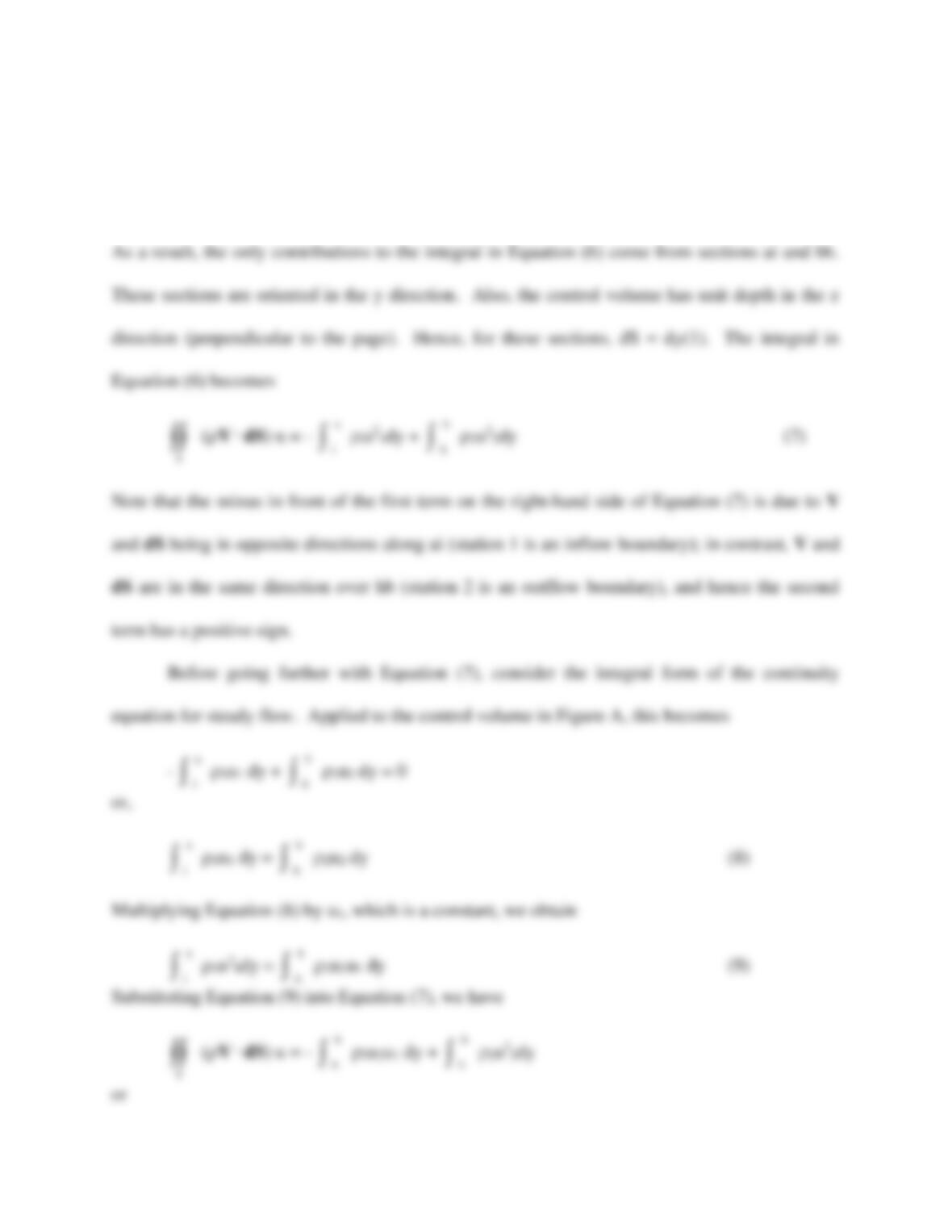
(V . dS) u = –
h
b
u2 (u1 – u2) dy (10)
Substituting Equation (10) into Equation (6) yields
D =
h
b
2u2 (u1 – u2) dy (11)
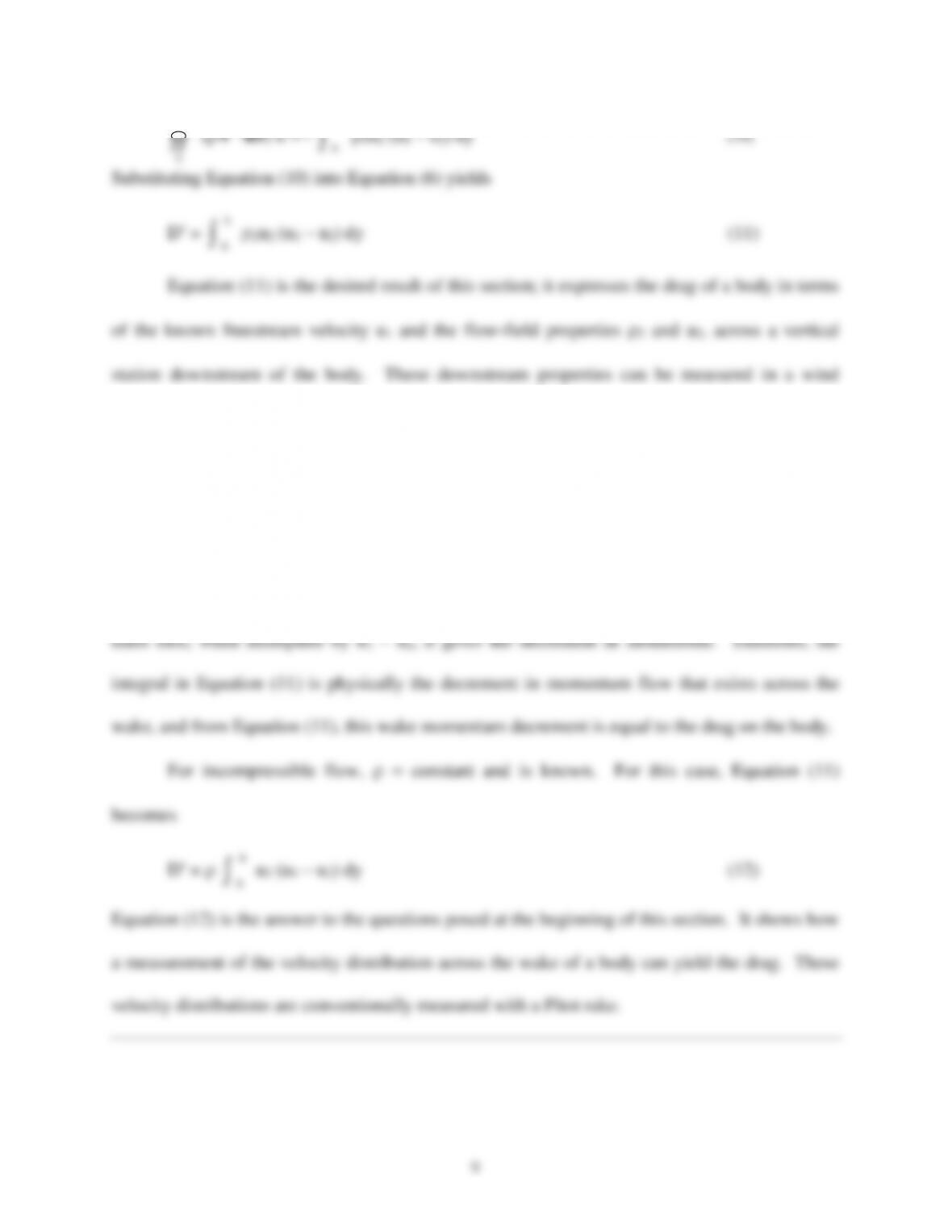
Equation (11) is the desired result of this section; it expresses the drag of a body in terms
of the known freestream velocity u1 and the flow-field properties 2 and u2, across a vertical
station downstream of the body. These downstream properties can be measured in a wind
tunnel, and the drag per unit span of the body D can be obtained by evaluating the integral in
Equation (11) numerically, using the measured data for 2 and u2 as a function of y.
Examine Equation (11) more closely. The quantity u1 – u2 is the velocity decrement at a
given y location. That is, because of the drag on the body, there is a wake that trails downstream
of the body. In this wake, there is a loss in flow velocity u1 – u2. The quantity 2u2 is simply the
h
b
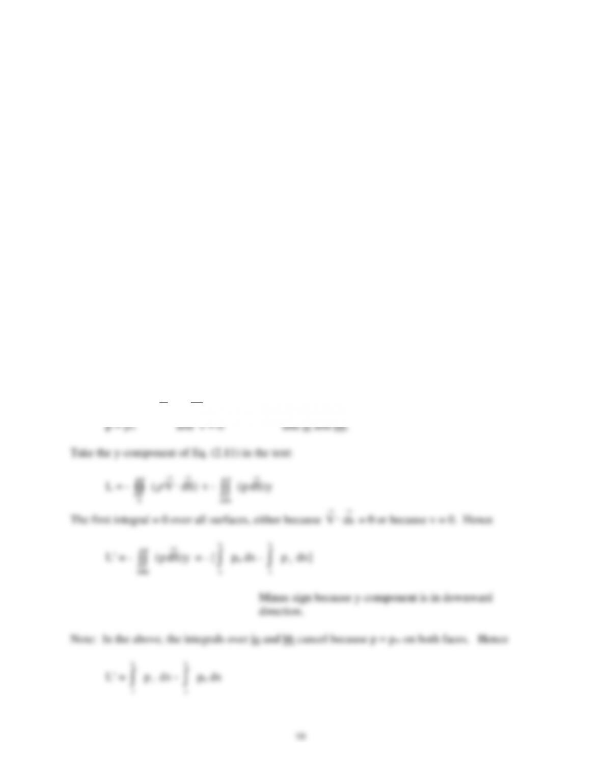
2.2
Denote the pressure distributions on the upper and lower walls by pu(x) and p
(x) respectively.
The walls are close enough to the model such that pu and p
are not necessarily equal to p.
Assume that faces ai and bh are far enough upstream and downstream of the model such that
a
i
a