160)
160)
When testing a normally open relay contact with a de–energized coil it should measure:
A)
Infinite or OL on digital meters.
B)
Some measurable resistance depending on the design of the relay.
C)
.
D)
None of the above.
Answer:
A
Explanation:
A)
B)
C)
D)
161)
161)
The motor starter is switched on and off by the:
A)
Contactors that are switched on and off by the motor relays.
B)
Motor relays that are switched on and off by the control relays.
C)
Contactors that are switched on and off by the control relays.
D)
Control relays that are switched on and off by contactors.
Answer:
B
Explanation:
A)
B)
C)
D)
162)
162)
________ block high–frequency signals and conduct low–frequency signals, while ________ do the
reverse on VFD systems.
A)
Resistors, capacitors
B)
Capacitors, inductors
C)
Inductors, capacitors
D)
Capacitors, resistors
Answer:
C
Explanation:
A)
B)
C)
D)
163)
163)
Heavy duty relays are not suitable as switching relays because they have:
A)
Larger contacts with less resistance.
B)
Smaller contacts with more resistance.
C)
Larger contacts with more resistance.
D)
Smaller contacts with less resistance.
Answer:
C
Explanation:
A)
B)
C)
D)
41
164)
164)
Which of the following is a device that does not switch motor contactors and starters on and off
but instead are used to directly start motors?
A)
Heavy–duty relay
B)
Pulley
C)
Thermostat
D)
Light–duty relay
Answer:
A
Explanation:
A)
B)
C)
D)
165)
165)
A serious problem common only to three phase motors is:
A)
Single phasing.
B)
Excessive time on locked rotor amperage.
C)
Operation at voltages that are too high.
D)
Excessive load.
Answer:
A
Explanation:
A)
B)
C)
D)
166)
166)
When a relay coil is disconnected and tested, what is the meter reading of an open coil?
A)
0 Ohms
B)
120 Ohms
C)
20 Ohms
D)
Infinite ohms or OL on digital meters
Answer:
D
Explanation:
A)
B)
C)
D)
167)
167)
The number of pulses per second from IGBTs is referred to as:
A)
Carrier frequency.
B)
Harmonics.
C)
Voltage fluctuation.
D)
Hertz modulation.
Answer:
A
Explanation:
A)
B)
C)
D)
42
168)
168)
The most common concern with using VFDs is:
A)
Harmonic distortion.
B)
Hertz modulation.
C)
Carrier frequency.
D)
Voltage fluctuation.
Answer:
A
Explanation:
A)
B)
C)
D)
169)
169)
A variable frequency drive is a system for controlling the rotational speed of an electric motor by:
A)
Controlling the frequency of the power supplied to it.
B)
Varying the load applied to it.
C)
Controlling the voltage amplitude supplied to it.
D)
Varying the current flow to it.
Answer:
A
Explanation:
A)
B)
C)
D)
170)
170)
Magnetic overload relays:
A)
Only slightly affected by ambient temperatures.
B)
Are made up of a sealed tube completely filled with a fluid.
C)
Are current sensitive.
D)
All of the above.
Answer:
D
Explanation:
A)
B)
C)
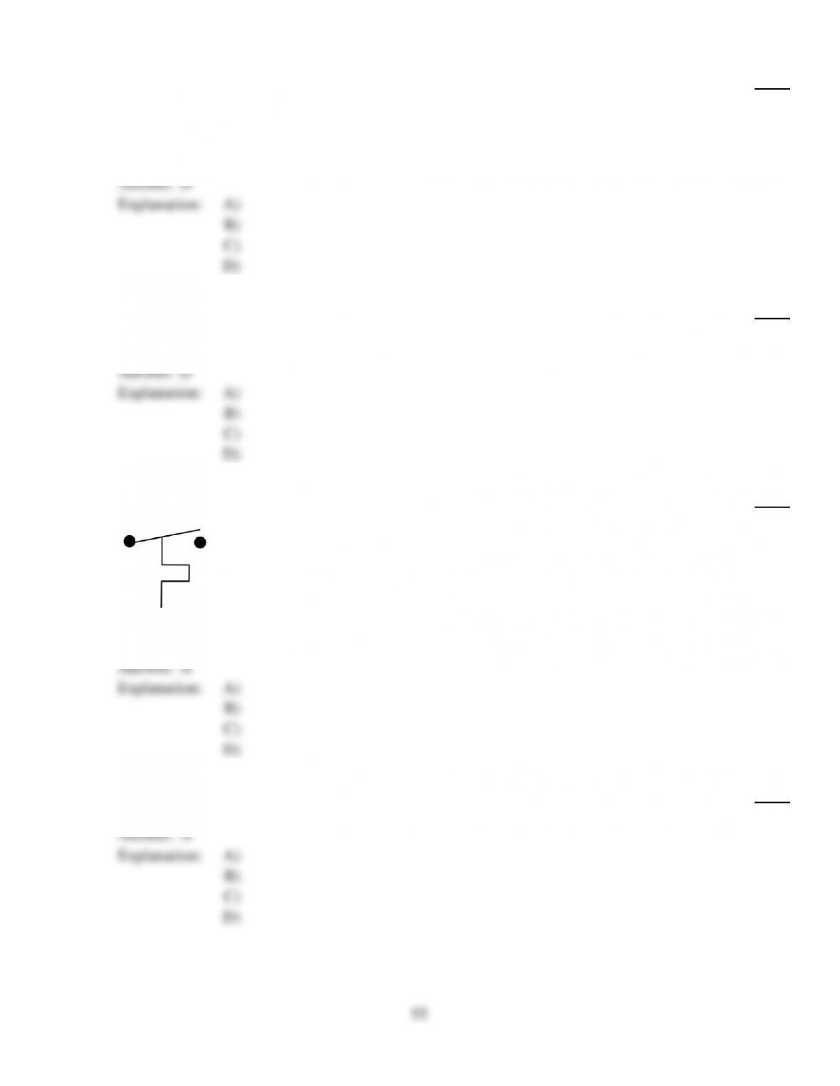
D)
171)
171)
The contacts of a ________ are generally made of fine silver alloy designed for low current.
A)
contactor
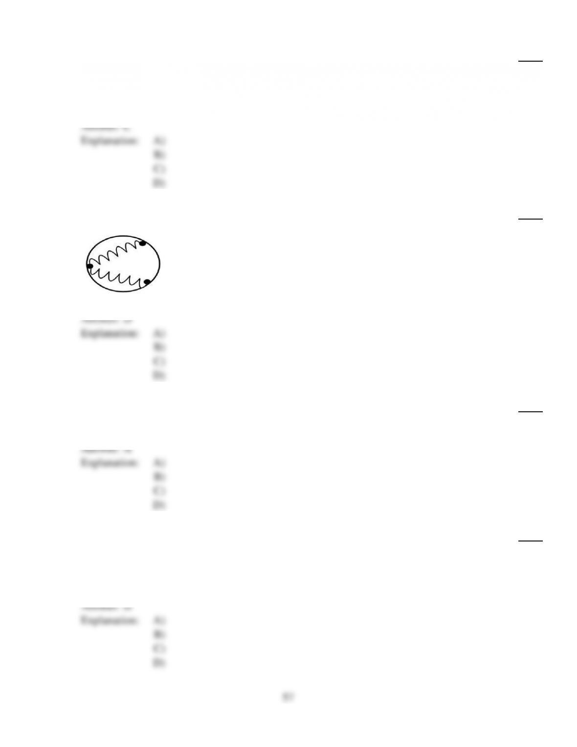
B)
heavy–duty relay
C)
motor starter
D)
light–duty relay
Answer:
D
Explanation:
A)
B)
C)
D)
43
172)
172)
Normally open contacts on a relay will read:
A)
infinity or OL when the relay is de–energized and 20 when energized.
B)
0 when the relay is de–energized and infinity or OL when energized.
C)
infinity or OL when the relay is de–energized and 0 when energized.
D)
20 when the relay is de–energized and infinity or OL when energized.
Answer:
C
Explanation:
A)
B)
C)
D)
173)
173)
Which of these can be used as a switching relay?
A)
Contactor
B)
Light–duty relay
C)
Heavy–duty relay
D)
Motor starter
Answer:
B
Explanation:
A)
B)
C)
D)
174)
174)
A device that does not switch on and off motors directly is a:
A)
Contactor.
B)
Heavy–duty relay.
C)
Motor starter.
D)
Light–duty relay.
Answer:
D
Explanation:
A)
B)
C)
D)
175)
175)
Pilot–duty overloads operate like:
A)
Relays.
B)
Motor Starters.
C)
Contactors.
D)
All of the above.
Answer:
A
Explanation:
A)
B)
C)
D)
44
176)
176)
A rate compensated type motor overload device is the:
A)
Thermal overload relay.
B)
Magnetic overload.
C)
Heater element current overload.
D)
General Electric Thermotector.
Answer:
D
Explanation:
A)
B)
C)
D)
177)
177)
Typically relay contacts are rated for amperage less than:
A)
30 amps.
B)
20 amps.
C)
50 amps.
D)
15 amps.
Answer:
D
Explanation:
A)
B)
C)
D)
178)
178)
A contactor‘s LRA rating may be:
A)
2 to 3 times as high as its FLA rating.
B)
3 to 4 times as high as its FLA rating.
C)
8 to 10 times as high as its FLA rating.
D)
4 to 5 times as high as its FLA rating.
Answer:
D
Explanation:
A)
B)
C)
D)
179)
179)
When checking the resistance of a dual voltage delta motor there should be ________ resistance
readings.
A)
12
B)
3
C)
9
D)
6
Answer:
C
Explanation:
A)
B)
C)
D)
45

180)
180)
Motor starting components can be made up of:
A)
Internal and external centrifugal switches only.
B)
Toggle switches, external centrifugal switches, and relays.
C)
Starting and running capacitors only.
D)
Internal centrifugal switches, relays, starting, and running capacitors.
Answer:
D
Explanation:
A)
B)
C)
D)
181)
181)
Potential relays measure the back ________ developed across the ________ winding to operate the
relay.
A)
emf, start
B)
emf, run
C)
amp draw, run
D)
amp draw, start
Answer:
A
Explanation:
A)
B)
C)
D)
182)
182)
Vertical mount fan motors require ________ to handle the force of the shaft pushing against the
end bells of the motor.
A)
flat washers
B)
thrust washers
C)
bronze bearings
D)
thrust bearings
Answer:
D
Explanation:
A)
B)
C)
D)
183)
183)
An open winding falls into which general motor failure area?
A)
Electrical problem
B)
Mechanical problems
C)
Motor starting components
D)
Attitude problem
Answer:
A
Explanation:
A)
B)
C)
D)
46
184)
184)
Which of the following formulas can be used to calculate fan speed (RPM)?
A)
Fan RPM =Fan Sheave Diameter × Motor Sheave Diameter
Motor RPM
B)
Fan RPM =Motor RPM ×
Fan Sheave Diameter
Motor Sheave Diameter
C)
Fan RPM =Motor RPM
Motor Sheave Diameter × Fan Sheave Diameter
D)
Fan RPM =Motor RPM ×
Motor Sheave Diameter
Fan Sheave Diameter
Answer:
D
Explanation:
A)
B)
C)
D)
185)
185)
The strength of an electric motor is rated in:
A)
Service factor.
B)
Horsepower.
C)
Full load amps.
D)
RPM.
Answer:
B
Explanation:
A)
B)
C)
D)
186)
186)
Which type of drive is used to make large changes in RPM or torque from the RPM and torque of
the motor?
A)
Belt drive
B)
Overdrive
C)
Gear drive
D)
Direct drive
Answer:
C
Explanation:
A)
B)
C)
D)
187)
187)
An open internal motor overload is distinguished by:
A)
Infinite resistance between start and common.
B)
Infinite resistance between run and common.
C)
Measurable resistance between run and start.
D)
All of these.
Answer:
D
Explanation:
A)
B)
C)
D)
47
188)
188)
Manufacturers often recommend adding what component to split systems with unusually long
refrigerant lines?
A)
Current relay
B)
Hard start kit
C)
Induction coil
D)
Electric boost kit
Answer:
B
Explanation:
A)
B)
C)
D)
189)
189)
The RPM of a belt driven blower can be determined by:
A)
Multiplying motor and fan sheave diameter and then divide by the motor RPM.
B)
Multiplying motor RPM and motor sheave diameter and then divide by the fan sheave
diameter.
C)
Multiplying motor and fan sheave diameter and then dividing that total into the motor
RPM.
D)
Multiplying motor RPM and fan sheave diameter and then divide by the motor sheave
diameter.
Answer:
B
Explanation:
A)
B)
C)
D)
190)
190)
Motors that sit on resilient rubber rings typically use which type of mounting?
A)
Cradle mount
B)
Flange mount
C)
Stud mount
D)
Belly band
Answer:
A
Explanation:
A)
B)
C)
D)
191)
191)
When checking the resistance of a dual voltage wye motor there should be ________ resistance
readings.
A)
12
B)
6
C)
3
D)
9
Answer:
B
Explanation:
A)
B)
C)
D)
48
192)
192)
Which NEMA classification that can withstand the highest temperature?
A)
Class F
B)
Class B
C)
Class A
D)
Class H
Answer:
D
Explanation:
A)
B)
C)
D)
193)
193)
A one horsepower motor with a service factor of 1.2 can safely produce:
A)
1.0 HP.
B)
1.2 HP.
C)
1.15 HP.
D)
0.9 HP.
Answer:
B
Explanation:
A)
B)
C)
D)
194)
194)
Larger blower wheels are typically operated by ________ motors.
A)
PSC
B)
belt driven
C)
capacitor start
D)
shunt field
Answer:
B
Explanation:
A)
B)
C)
D)
195)
195)
Solid state start relays can be checked by:
A)
Checking voltage drop across the relay.
B)
Amp checking with a current spike at startup and drop to 0 amps after compressor is
running.
C)
Ohm checking through them when they are cold.
D)
Both A and B.
Answer:
D
Explanation:
A)
B)
C)
D)
196)
196)
On PSC multi–speed indoor blowers the wire that is wired to power regardless of speed is the
________ wire.
A)
Blue
B)
Red
C)
Common
D)
Orange
Answer:
C
Explanation:
A)
B)
C)
D)
49
197)
197)
The correct tension for any belt drive application is:
A)
1/64 Inch deflection per 1 inch span between drive shaft and driven shaft.
B)
Tight enough so that it does not slip on startup.
C)
The minimum tension required to keep the belt from slipping at its maximum torque.
D)
All of the these are indicators of correct tension.
Answer:
D
Explanation:
A)
B)
C)
D)
198)
198)
Nearly all air conditioning condenser fans are ________ motors.
A)
capacitor start capacitor run
B)
shunt field
C)
PSC
D)
capacitor start
Answer:
C
Explanation:
A)
B)
C)
D)
199)
199)
What term expresses the ability of the motor to work beyond its rated output?
A)
Horsepower
B)
RPM
C)
Full load amps
D)
Service factor
Answer:
D
Explanation:
A)
B)
C)
D)
200)
200)
What information does a factual diagram give that a ladder diagram does not?
A)
The American Wire Gauge for each wire on the diagram
B)
Where the actual components are located
C)
Information about specific wire routing, wire color, and terminal labeling
D)
What the actual components look like
Answer:
C
Explanation:
A)
B)
C)
D)
50
201)
201)
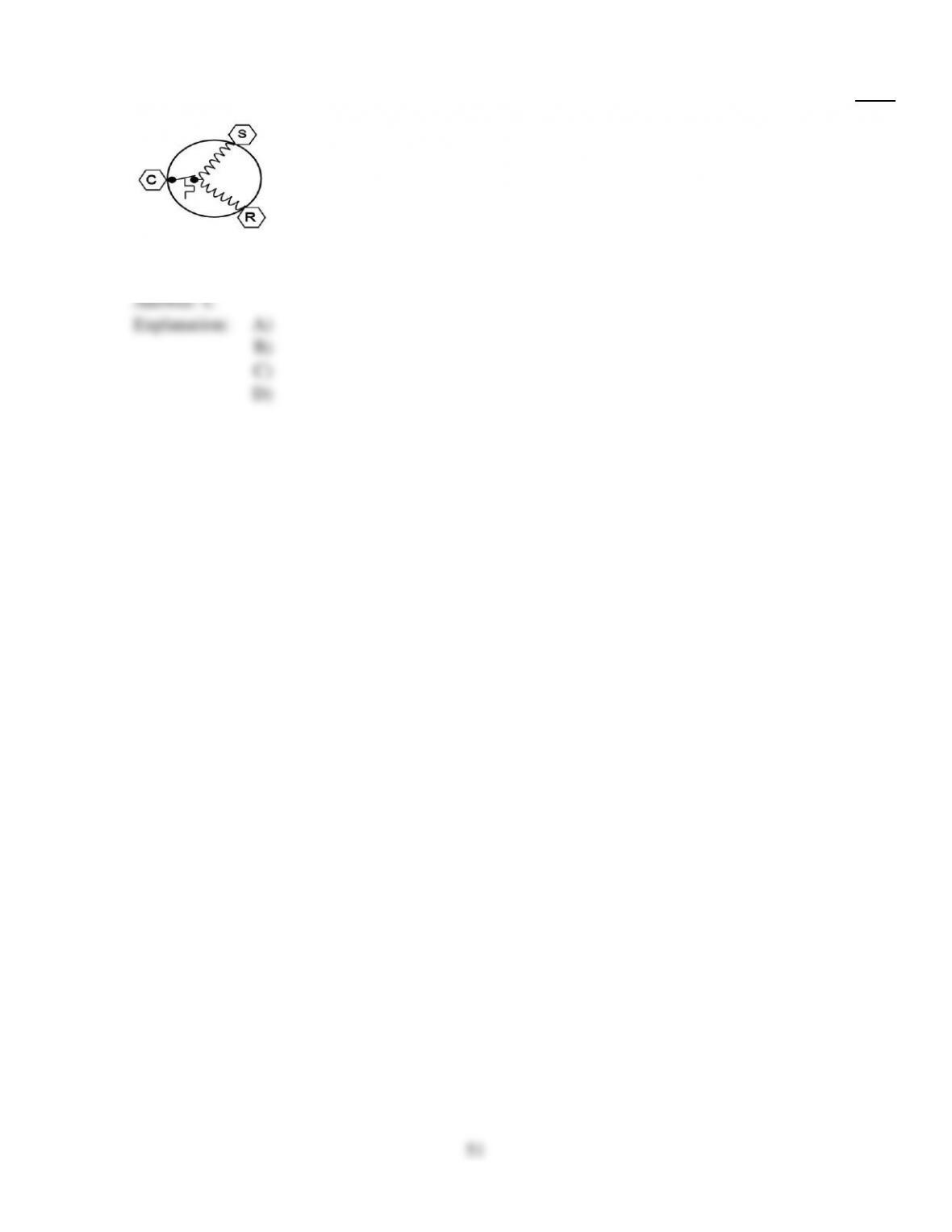
This symbol represents:
A)
Transformer.
B)
Three–phase motor.
C)
Compressor with internal overload.
D)
Single–phase motor.
Answer:
C
Explanation:
A)
B)
C)
D)
51

202)
202)
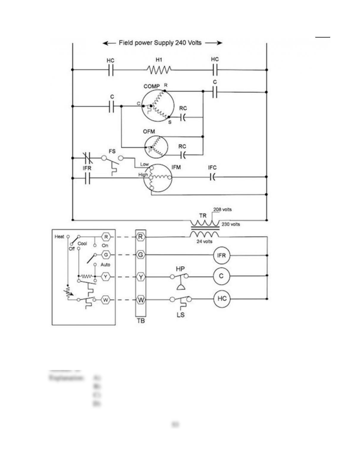
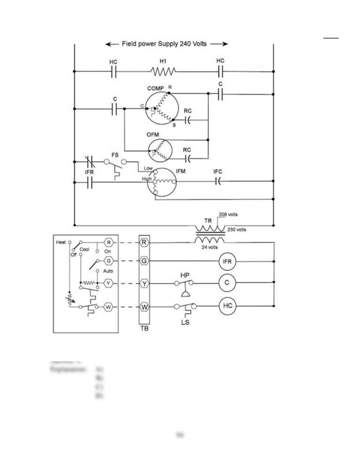
Heat is provided by:
A)
The compressor.
B)
The electric heat strip.
C)
The compressor and the condenser fan.
D)
The indoor fan.
Answer:
B
Explanation:
A)
B)
C)
D)
52
203)
203)
The fan operates on high speed:
A)
During the cooling cycle.
B)
During both the heating and cooling cycles.
C)
During the heating cycle.
D)
Anytime the indoor fan relay coil is energized.
Answer:
D
Explanation:
A)
B)
C)
D)
53
204)
204)
The contactor controls:
A)
The indoor fan.
B)
The condenser fan.
C)
The compressor and the condenser fan.
D)
The compressor.
Answer:
C
Explanation:
A)
B)
C)
D)
54
205)
205)
The purpose of the schematic diagram is:
A)
To show how the power and control wiring connect to the unit.
B)
To show how and where all the wires inside the unit are connected.
C)
To show the location of all the electrical components.
D)
To show the scheme, or logic, of the electrical circuitry.
Answer:
D
Explanation:
A)
B)
C)
D)
206)
206)
A normally open set of relay contacts will close when:
A)
Power is not applied to the contacts.
B)
Power is not applied to the relay coil.
C)
Power is applied to the contacts.
D)
Power is applied to the relay coil.
Answer:
D
Explanation:
A)
B)
C)
D)
207)
207)
This symbol represents:
A)
Heating thermostat.
B)
Cooling thermostat.
C)
Close–on–rise pressure switch.
D)
Open–on–rise pressure switch.
Answer:
A
Explanation:
A)
B)
C)
D)
208)
208)
This type of diagram provides the technician with the unit’s sequence of operations.
A)
Ladder
B)
Pictorial
C)
Point–to–point
D)
Schematic
Answer:
A
Explanation:
A)
B)
C)
D)
55
209)
209)
What do the rails on a ladder diagram represent?
A)
The circuit loads
B)
The individual circuits
C)
The line voltage power
D)
The rails on each ladder diagram stand for something different.
Answer:
C
Explanation:
A)
B)
C)
D)
210)
210)
The component location diagram:
A)
Shows the operating sequence of the system components.
B)
Is used to locate actual parts and connections within the unit itself.
C)
Gives the network address of each piece of equipment in the multicomponent cooling
network.
D)
Shows how the unit interfaces with other units in a multicomponent cooling network.
Answer:
B
Explanation:
A)
B)
C)
D)
211)
211)
What is the difference between a load and a control?
A)
Loads use power. Controls either let power pass or they do not let it pass.
B)
Loads are the power, as in L1 and L2. Controls use the power.
C)
Controls use power. Loads either let power pass or they do not let it pass.
D)
There is no difference. They are two words for the same thing.
Answer:
A
Explanation:
A)
B)
C)
D)
212)
212)
The point in an electrical circuit schematic where high voltage is stepped down to low voltage is at
what component?
A)
Relay
B)
Transformer
C)
Solenoid
D)
Contactor
Answer:
B
Explanation:
A)
B)
C)
D)
56
213)
213)
Electrical symbols in ladder and schematic diagrams:
A)
Are unique to each component.
B)
Look like the components they represent.
C)
Represent electrical properties of common components.
D)
Are standard throughout the industry.
Answer:
C
Explanation:
A)
B)
C)
D)
214)
214)
This symbol represents:
A)
Heater.
B)
Light.
C)
Transformer.
D)
Motor.
Answer:
D
Explanation:
A)
B)
C)
D)
215)
215)
How is field wiring shown on most diagrams?
A)
With dashed lines
B)
In red
C)
In blue
D)
With solid lines
Answer:
A
Explanation:
A)
B)
C)
D)
216)
216)
In ladder diagrams, component symbols are placed:
A)
Only at the intersection points.
B)
By their actual physical location in the unit.
C)
In sequential order according to each component’s model number.
D)
By their function in the circuit.
Answer:
D
Explanation:
A)
B)
C)
D)
57
217)
217)
Why is there a potential of 24 V between the R terminal and the other terminals on a thermostat
subbase when the thermostat is not calling?
A)
Thermostats have battery backup, which can be read between R and the other terminals
when the thermostat is not calling.
B)
Thermostats are wired with both sides of 24 V. One side is supplied to the R terminal and
the other to all the remaining terminals.
C)
The common side of 24 V is supplied through the coils of the devices that are not operating.
D)
The meter is reading voltage that is left in the thermostat wire from the previous operating
cycle.
Answer:
C
Explanation:
A)
B)
C)
D)
218)
218)
Most switches used for safety controls in HVAC circuits:
A)
Are normally closed and wired in parallel with the load they protect.
B)
Are normally closed and wired in series with the load they protect.
C)
Are normally open and wired in parallel with the load they protect.
D)
Are normally open and wired in series with the load they protect.
Answer:
B
Explanation:
A)
B)
C)
D)
219)
219)
In most 24 V AC low–voltage systems the red wire is hot, the yellow wire is the cooling circuit,
and the green wire controls the:
A)
Gas valve.
B)
Fan circuit.
C)
Compressor.
D)
Heater element.
Answer:
B
Explanation:
A)
B)
C)
D)
58

220)
220)
A difference between a straight heat–cool thermostat and a heat pump thermostat is that:
A)
Y and W swap functions.
B)
Y is energized in both heating and cooling.
C)
Y is energized in heating instead of cooling.
D)
Heat pump thermostats do not energize the fan in the heating cycle.
Answer:
B
Explanation:
A)
B)
C)
D)
221)
221)
Pneumatic controls operate by:
A)
Hydraulic pressure.
B)
Water pressure.
C)
Electricity.
D)
Air pressure.
Answer:
D
Explanation:
A)
B)
C)
D)
222)
222)
A system that monitors the return air temperature to control room temperature is:
A)
An integrated–loop control system.
B)
A closed–loop control system.
C)
An ambient–loop control system.
D)
An open–loop control system.
Answer:
B
Explanation:
A)
B)
C)
D)
223)
223)
The newest HVACR control systems operate by:
A)
Providing a modulating air pressure in response to monitored conditions.
B)
Processing electronic signals with a microprocessor.
C)
Turning relay coils on or off to complete circuits.
D)
Providing a varying DC voltage in response to monitored conditions.
Answer:
B
Explanation:
A)
B)
C)
D)
59
224)
224)
A system that monitors the outdoor temperature to control some aspect of system operation is:
A)
An ambient–loop control system.
B)
An integrated–loop control system.
C)
An open–loop control system.
D)
A closed–loop control system.
Answer:
C
Explanation:
A)
B)
C)
D)
225)
225)
A modulating control:
A)
Can modulate mechanical signals to wireless frequencies for remote control.
B)
Can be used with any voltage by adjusting the modulator setting.
C)
Is mainly an off–and–on type of control.
D)
Can position a damper or valve to positions other than full open or closed.
Answer:
D
Explanation:
A)
B)
C)
D)
226)
226)
When is the B terminal energized on most low–voltage thermostats?
A)
Whenever the thermostat calls for first–stage heat
B)
Whenever the thermostat calls for cooling
C)
Whenever the system switch is moved to “Heat”
D)
Whenever the system switch is moved to “Cool”
Answer:
C
Explanation:
A)
B)
C)
D)
227)
227)
Direct digital controls (DDC) operate by:
A)
Turning relay coils on or off to complete circuits.
B)
Processing electronic signals with a microprocessor.
C)
Providing a modulating air pressure in response to monitored conditions.
D)
Providing a varying DC voltage in response to monitored conditions.
Answer:
B
Explanation:
A)
B)
C)
D)
60