CHAPTER 8:
SYSTEMS
OBJECTIVES
• Define control loop, and identify the five elements of a control loop.
• Draw a level control loop.
• Draw a pressure control loop.
• Draw a flow control loop.
• Draw a temperature control loop.
• Discuss the function of transmitters.
REVIEW QUESTIONS
1. List the three basic designs for valve actuators..
2. Describe the terms “air to open” and “air to close.”
3. Define proportional control.
4. Describe rate and reset.
5. List the primary elements and sensors associated with flow.
6. List the primary elements and sensors associated with level.
7. List the primary elements and sensors associated with pressure.
8. List the primary elements and sensors associated with temperature.
9. List the five elements of a control loop.
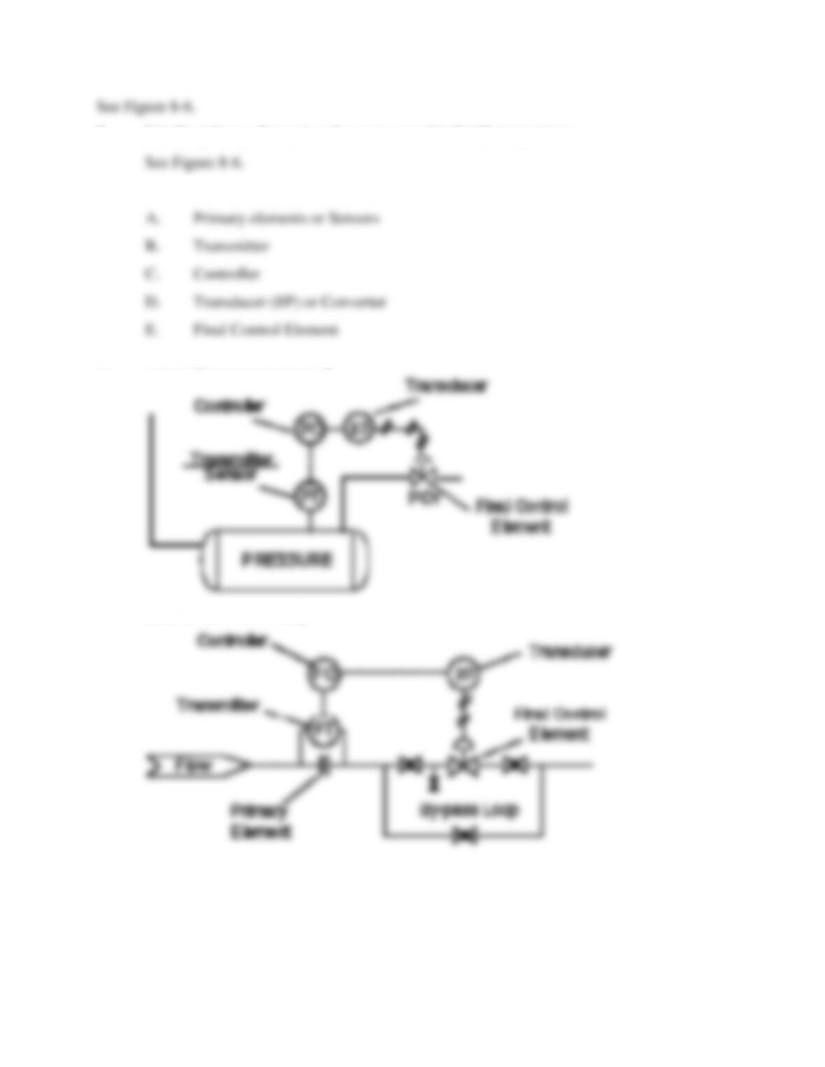
10. Draw a pressure control loop.
11. Draw a flow control loop.
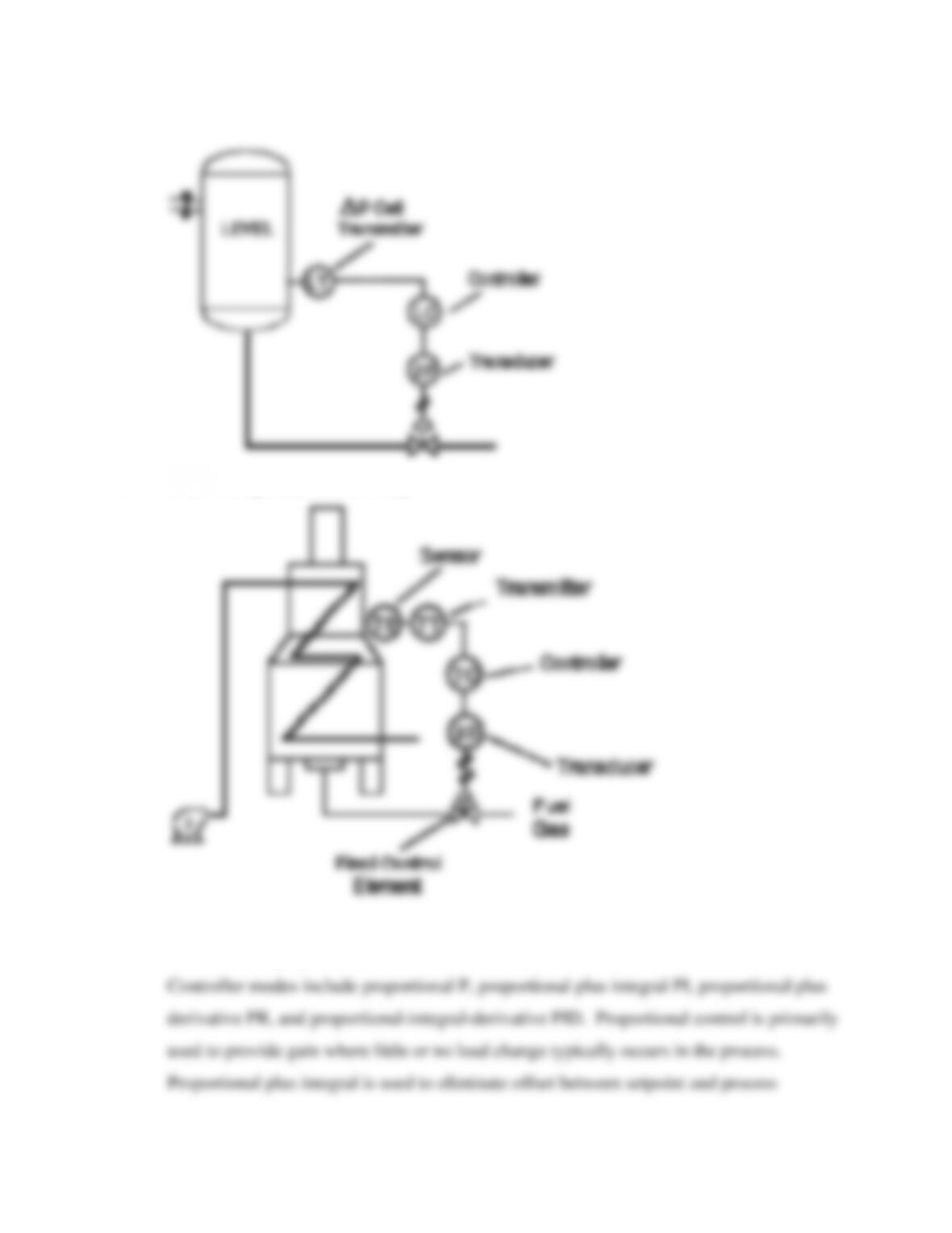
12. Draw a level control loop.
13. Draw a temperature control loop.
14. Describe how proportional control works with reset.
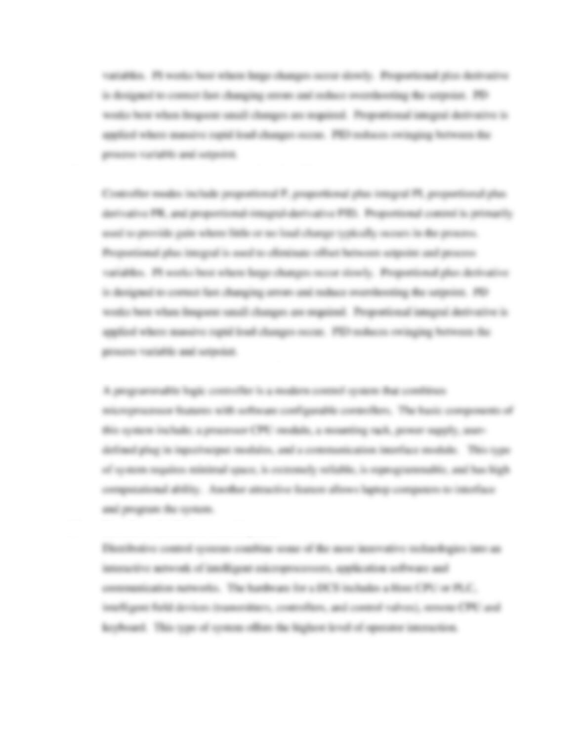
15. Describe how proportional control works with rate.
16. Describe a programmable logic controller.
17. Describe a distributive control system.
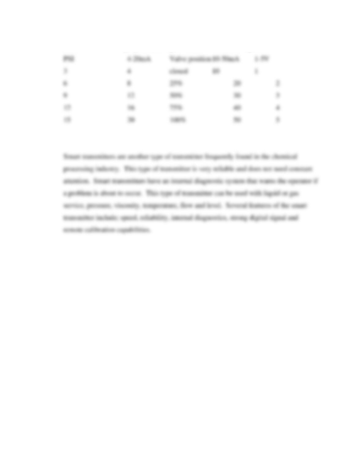
18. Describe how a 3-15 psi pneumatic signal relates to a 4-20 mA signal.
19. What is a smart transmitter, and what are some of its advantages?
CHAPTER EIGHT TEST:
PROCESS INSTRUMENTATION 2
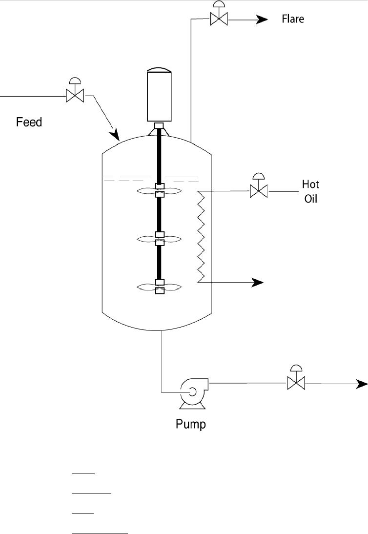
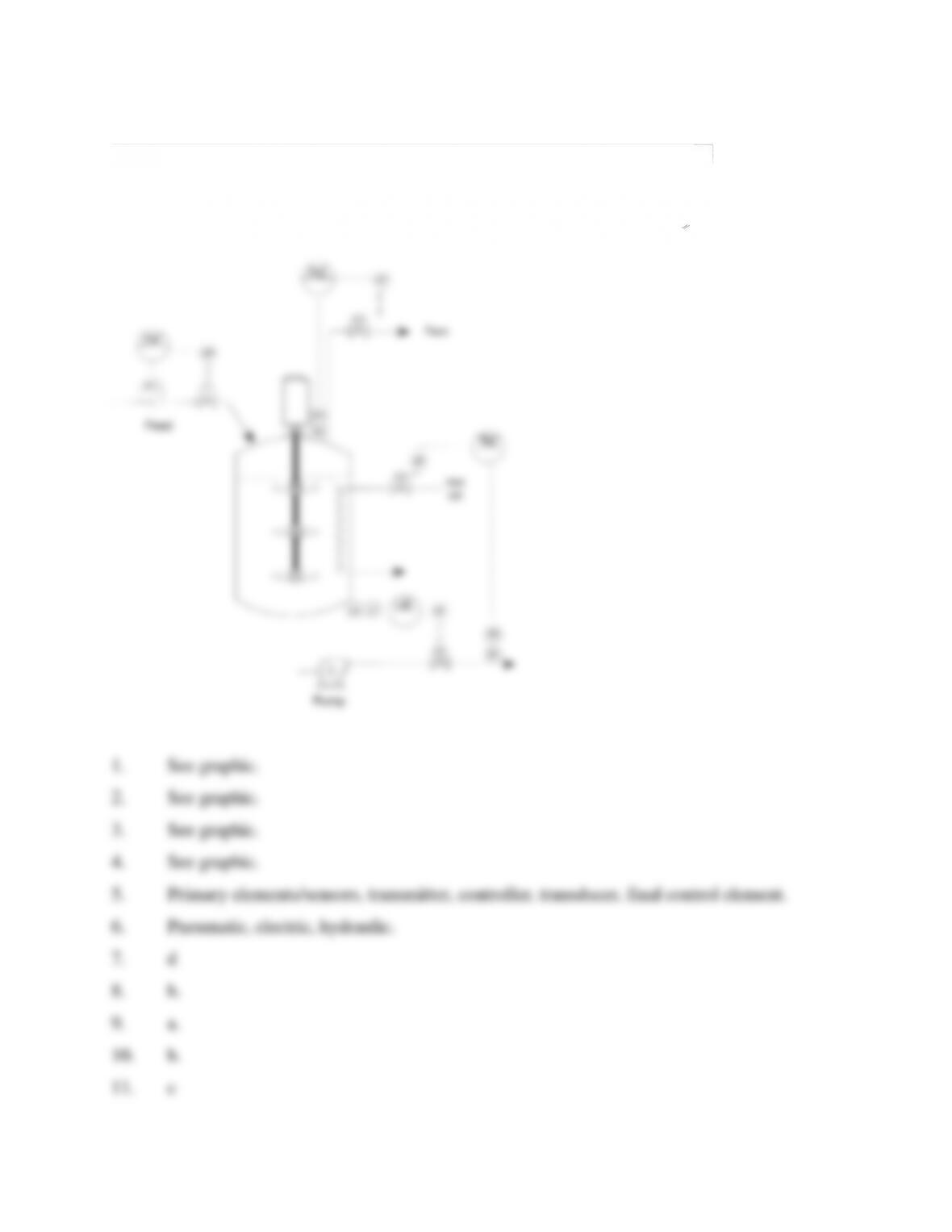
1. Draw a level control loop on the top graphic.
2. Draw a pressure control loop on the top graphic.
3. Draw a flow control loop on the top graphic.
4. Draw a temperature control loop on the top graphic.
5. List the five elements of a control loop.
6. List the three basic designs for valve actuators.
a._________________________
b. _________________________
c. _________________________
7. Rate or derivative mode is best described as:
a. describes how one control loop overrides the instruction of another.
b. reduces the difference between setpoint and process variable by adjusting the
controller output continuously until the offset is eliminated.
c. the difference between the upper and lower range limits.
d. enhances controller output by increasing the output in relationship to the changing
process variable.
8. Reset or Integral mode is best described as:
a. describes how one control loop overrides the instruction of another.
b. reduces the difference between setpoint and process variable by adjusting the
controller output continuously until the offset is eliminated.
c. the difference between the upper and lower range limits.
d. enhances controller output by increasing the output in relationship to the changing
process variable.
9. Range is best defined as:
a. The portion of the process controlled by the controller.
b. The difference between the upper and lower range limits.
c. Electrical frequency used by a controller.
d. Pneumatic pulse used to detect differences in process variables.
10. Span is best defined as:
a. The portion of the process controlled by the controller.
b. The difference between the upper and lower range limits.
c. Electrical frequency used by a controller.
d. Pneumatic pulse used to detect differences in process variables.
11. Proportional band is best described as:
a. The portion of the process controlled by the controller.
b. The difference between the upper and lower range limits.
c. The scaling factor used to take a controller from 0% to 100%.
d. Pneumatic pulse used to detect differences in process variables.
12. Describe what happens when a controller is placed in manual mode.
a. The control valve locks at a specific output.
b. The controller adjusts the control valve.
c. The control loop shuts down and the valve closes.
d. The controller automatically adjusts to match setpoint..
13. Describe what happens when a controller is placed in automatic mode:
a. The control valve locks at a specific output.
b. The controller adjusts the control valve.
c. The controller automatically adjusts to match setpoint.
d. The signal from another controller takes over.
14. A control loop is:
a. Collection of instruments that work together to automatically control a process.
b. Primary elements/sensors, transmitter, controller, transducer, final control
element.
c. Control valves, transmitters, controllers, temperature indicators.
d. a & b
15. A transmitter is best described as:
a. A device designed to convert a measurement into a signal.
b. Compares a signal to a setpoint.
c. Measurement device
d. A device designed to convert an air signal to an electric signal or an electric
ssignal to a pneumatic signal.
16. Primary elements for pressure come in the following designs: (Circle all that apply!)
a. bourdon d. bellows
b. spiral e. bullet
c. helical f. hand-held
17. A transducer is best described as:
a. A device designed to convert an air signal to an electric signal or an electric signal
to a pneumatic signal.
b. A device designed to convert a measurement into a signal.
c. A device designed to compare a signal to a setpoint.
d. A device used for measurement.
18. A 9 psi signal produces a 12 mA electric signal that equals a valve position of:
a. Closed
b. 25%
c. 50%
d. 75%
e. 100%
19. Cascade control is best described as:
a. A term used to describe how one control loop controls or overrides the
instructions of another control loop in order to achieve a desired setpoint.
b. A term used to describe when a control valve is locked into position.
c. A term used to describe automatic control of two or more control loops.
d. A term used to link a DCS and PLC together.
20. A DCS or PLC is best described as:
a. A window to the process that allows a technician to see and control process
variables.
b. A super computer linked to all electronic equipment.
c. Software designed to link a variety of computer equipment to process equipment.
d. A CPU linked to specific pods tied to a microprocessor and software.
ANSWER KEY CHAPTER 8 PROCESS INSTRUMENTS 2