37)
The parallel combination of a 330 resistor and a 470 resistor is connected in series with the
parallel combination of four 1 k resistors. If a 100 V source is connected across the circuit, then
which resistor carries the most current?
37)
A)
470
B)
330
C)
1 k
38)
If Vs= 12 V in Figure 6–3, what is the value of VEB if R3 shorts?
38)
A)
–3 V
B)
6 V
C)
8 V
D)
–8 V
39)
If VR4 = 10 V in Figure 6–3, what is the value of VAD?
39)
A)
20 V
B)
40 V
C)
10 V
D)
30 V
40)
In a two–source circuit, one source alone produces 10 mA through a branch. If the other source
alone produces 8 mA in the opposite direction through the same branch, what is the total current
through the branch?
40)
A)
8 mA
B)
18 mA
C)
2 mA
D)
10 mA
41)
In the series portion of series–parallel circuits, the total resistance is:
41)
A)
equal to the largest resistance.
B)
less than any one resistance.
C)
less than the largest resistance.
D)
greater than the largest resistance.
42)
If four parallel 10 k resistors are in series with a single 20 k resistor and one of the parallel
resistors shorts, the voltage across the other parallel resistors ________.
42)
A)
decreases
B)
remains the same
C)
increases
43)
If Vs= 50 V in Figure 6–3, what is the value of VCA?
43)
A)
–25 V
B)
5 V
C)
25 V
D)
–5 V
44)
The super position theorem provides a method for:
44)
A)
designing complex series–parallel circuits.
B)
building complex series–parallel circuits.
C)
analyzing complex series–parallel circuits.
D)
all of these.
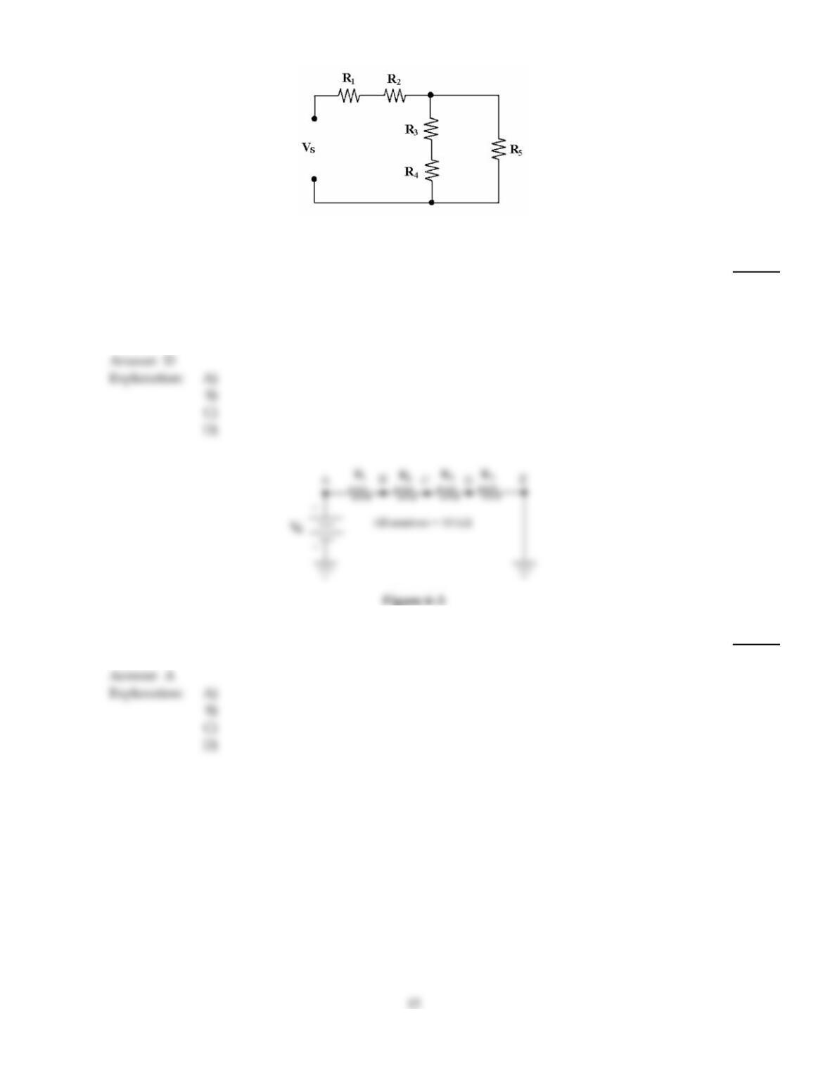
Figure 6–2
45)
In Figure 6–2, R3 and R4 are connected in ________.
45)
A)
series with R5
B)
parallel with each other
C)
series with R2
D)
series with each other and in parallel with R5
46)
If the current is 12 mA in Figure 6–3, what is the value of VEB?
46)
A)
–360 V
B)
–240 V
C)
240 V
D)
360 V
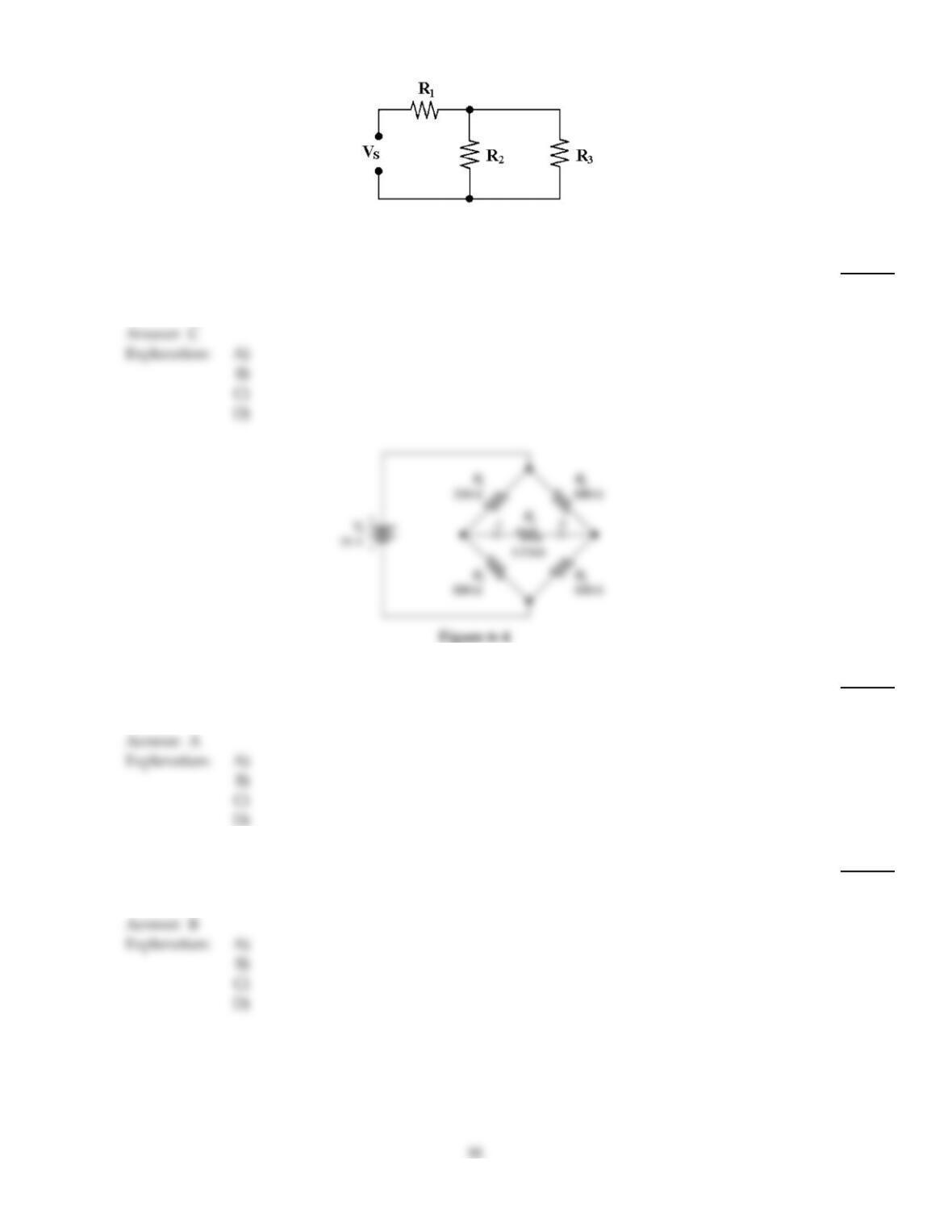
Figure 6–1
47)
In Figure 6–1, R2 is connected in ________.
47)
A)
series with R3
B)
parallel with R1
C)
parallel with R3
D)
series with R1
48)
Refer to Figure 6–4. If R1 is changed to 500 , the Thevenin resistance and voltage would be:
48)
A)
595 and 3 V.
B)
1 k and 3 V.
C)
595 and 807 mV.
D)
1 k and 807 mV.
49)
In solving series–parallel circuits using Ohm’s law, first solve for:
49)
A)
the series current.
B)
the parallel resistance.
C)
the series resistance.
D)
the parallel current.
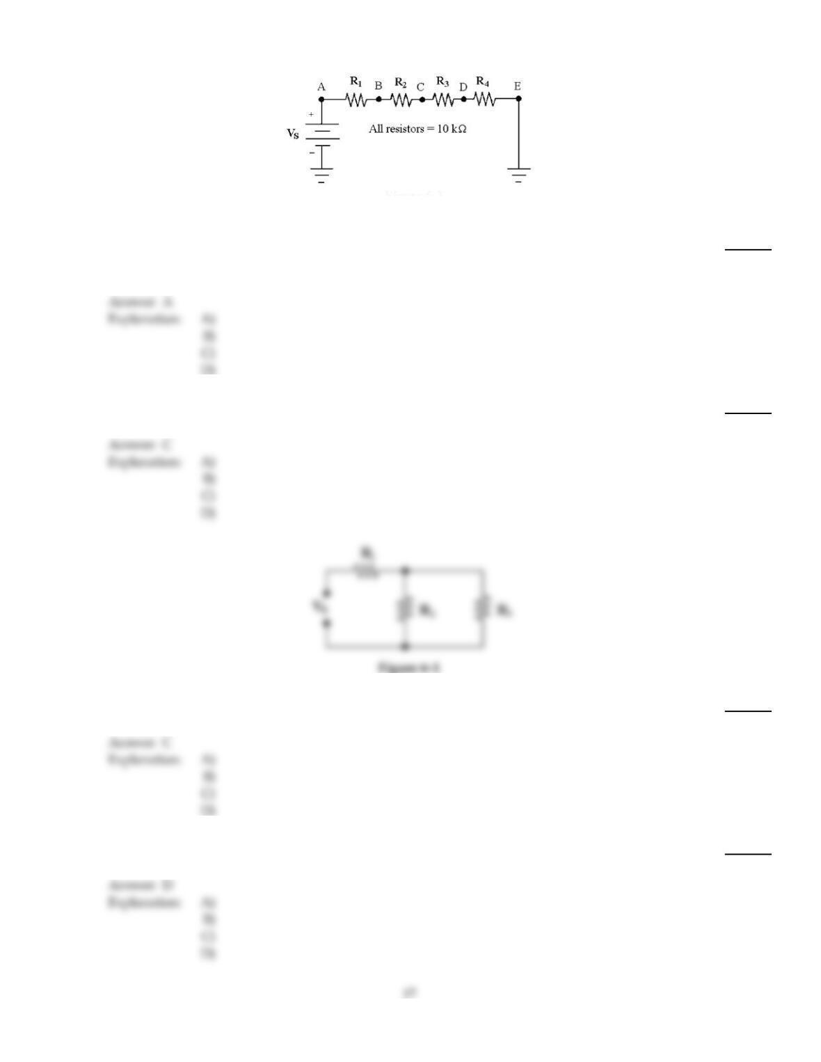
Figure 6–3
50)
If a fifth 10 k resistor is connected in series in Figure 6–3, how does VR4 change?
50)
A)
VR4 decreases.
B)
VR4 remains the same.
C)
VR4 increases.
D)
VR4 increases to 10 V.
51)
If Vs= 22 V in Figure 6–3, what is the is the value of VDB?
51)
A)
5.5 V
B)
–22 V
C)
–11 V
D)
11 V
52)
If R1= 4.7 k, R2= 3.3 k, R3= 1 k and Vs= 50 V in Figure 6–1, IT equals ________.
52)
A)
8.8 mA
B)
12.1 mA
C)
9.15 mA
D)
75.7 mA
53)
If Vs= 25 V, R1= 10 k, R2= 15 k and R3= 50 k in Figure 6–1, IT equals ________.
53)
A)
1.58 mA
B)
2.5 mA
C)
2.17 mA
D)
1.16 mA
54)
In solving series–parallel circuits using Ohm’s law, first solve for:
54)
A)
RT.
B)
IT.
C)
ET.
D)
any of these, it doesn’t matter.
55)
If all of the resistors in Figure 6–2 are 4.7 k, what is the value of RT?
55)
A)
18.8 k
B)
9.4 k
C)
4.7 k
D)
12.5 k
56)
If R2 opens in Figure 6–2, VR3 ________.
56)
A)
decreases
B)
remains the same
C)
increases
D)
causes the fuse to blow
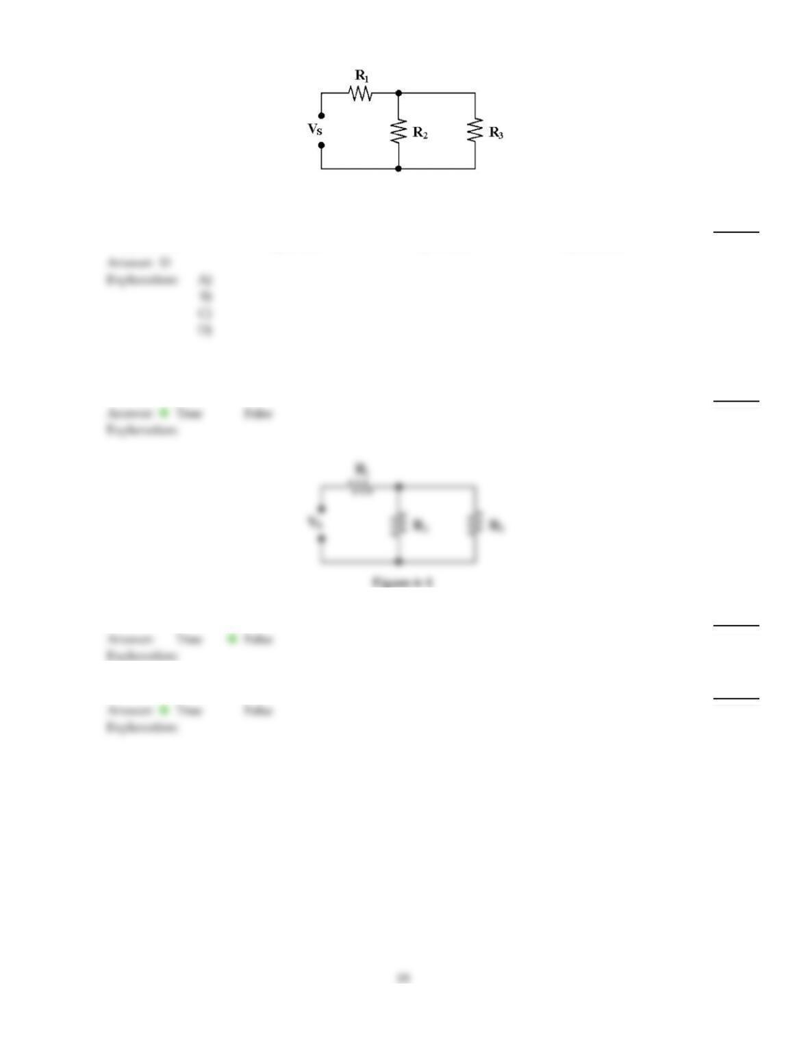
Figure 6–1
57)
If R1= 10 k, R2= 15 k and R3= 50 k in Figure 6–1, RT equals ________.
57)
A)
11.5 k
B)
10 k
C)
9.5 k
D)
21.5 k
TRUE/FALSE. Write ‘T’ if the statement is true and ‘F’ if the statement is false.
58)
A loaded voltage divider is a series–parallel circuit.
58)
Figure 6–1
59)
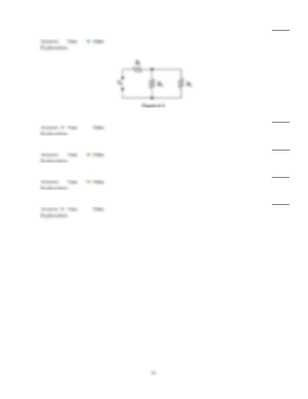
R1 is in series with R3 in Figure 6–1.
59)
60)
Two or more resistors connected in series form a circuit known as a voltage divider.
60)
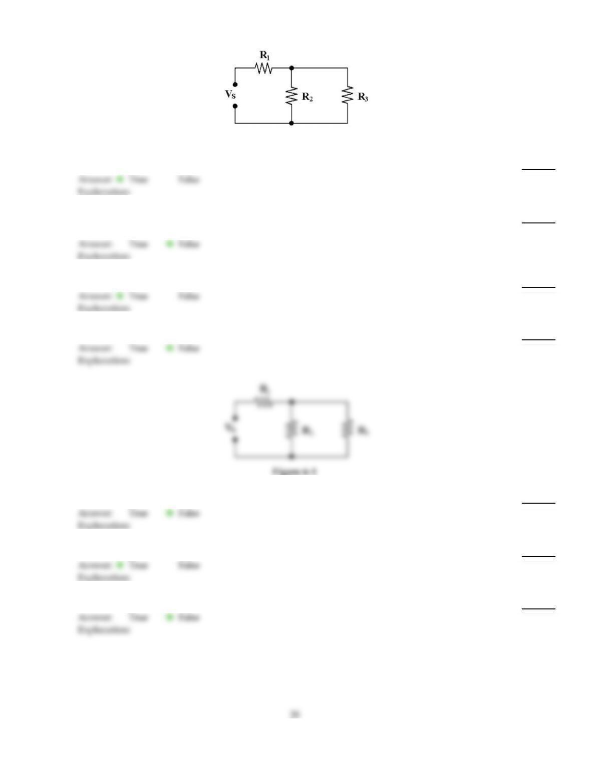
Figure 6–1
61)
R2 is in parallel with R3 in Figure 6–1.
61)
62)
Maximum power is achieved when the load resistance is approximately two times the source
resistance.
62)
63)
Thevinizing a circuit creates an equivalent series circuit.
63)
64)
A bridge circuit‘s resistances must all be of the same value to be in a balanced condition.
64)
Figure 6–1
65)
R1 is in series with the series combination R2 and R3 in Figure 6–1.
65)
66)
If two resistors are in parallel, they drop the same voltage.
66)
67)
If two resistors are in parallel, they carry the same current.
67)
68)
A voltmeter, when connected across a component, can be viewed as being a resistor in series with
that component.
68)
69)
R1 is in series with the parallel combination R2 and R3 in Figure 6–1.
69)
70)
The voltage across any open in a series–parallel circuit will be the source voltage.
70)
71)
No problems could occur if a 10 V source and a 20 V source were connected in parallel.
71)
72)
A series–parallel circuit consists of resistors in both series and parallel.
72)
Answer Key
Testname: C6
Answer Key
Testname: C6
23