Exam
Name___________________________________
MULTIPLE CHOICE. Choose the one alternative that best completes the statement or answers the question.
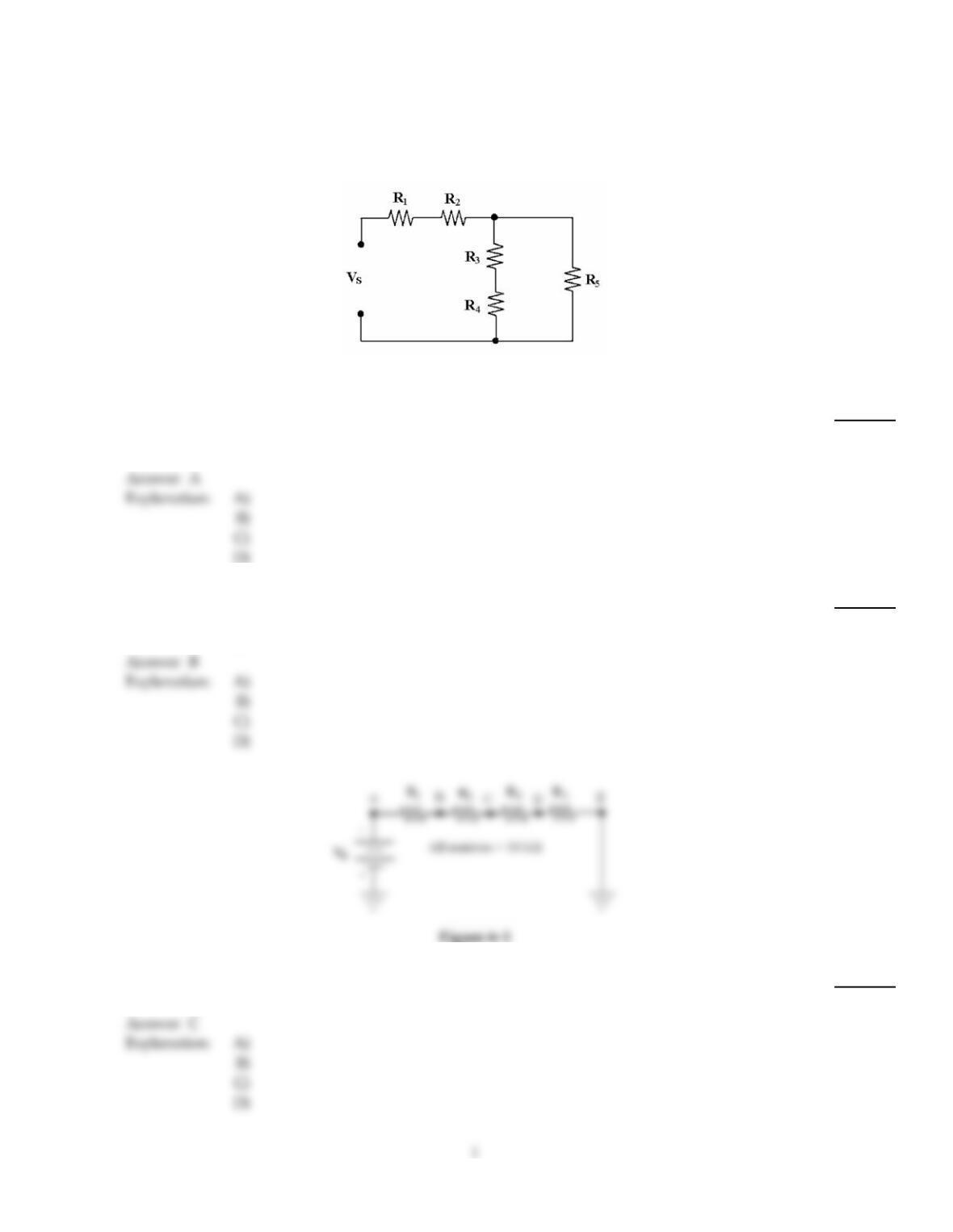
Figure 6–2
1)
If R1= 50 k, R2= 10 k, R3= 10 k, R4= 50 k and R5= 10 k in Figure 6–2, what is the value
of RT?
1)
A)
68.6 k
B)
130 k
C)
85.7 k
D)
8.57 k
2)
The Wheatstone bridge circuit is widely used to measure:
2)
A)
accurate currents.
B)
precise resistances.
C)
exact voltages.
D)
all of these.
3)
If VR1 = 15 V in Figure 6–3, what is the value of VBD?
3)
A)
–60 V
B)
–30 V
C)
30 V
D)
60 V
4)
If the current is 1.2 mA in Figure 6–3, what is the value of PT?
4)
A)
57.6 mW
B)
0.576 mW
C)
5.76 mW
D)
576 mW
5)
According to the maximum power transfer theorem, maximum power is delivered to any load
when the load resistance is:
5)
A)
less than one–half of the source resistance.
B)
at least twice or more than the source resistance.
C)
larger than source resistance.
D)
exactly equal to the source resistance.
D
6)
The parallel combination of a 330 resistor and a 470 resistor is connected in series with the
parallel combination of four 1 k resistors. If a 100 V source is connected across the circuit, then
which resistor drops the most voltage?
6)
A)
1 k
B)
470
C)
330
A
7)
Thevenin’s theorem provides a method for:
7)
A)
designing complex series–parallel circuits.
B)
simplifying complex series–parallel circuits.
C)
building complex series–parallel circuits.
D)
all of these.
B
A
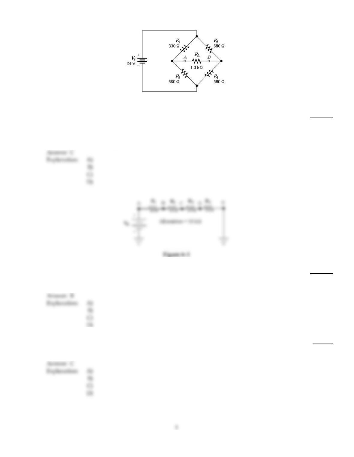
Figure 6–4
8)
Refer to Figure 6–4. With circuit balanced there is:
8)
A)
maximum current flow through the load.
B)
Cannot be determined without detailed analysis.
C)
no current through the load.
D)
no current flow through the total circuit.
9)
If a 10 k resistor is placed in parallel with R4 in Figure 6–3, how will VR4 change?
9)
A)
VR4 will change to 4 volts.
B)
VR4 will decrease.
C)
VR4 will remain the same.
D)
VR4 will increase.
10)
The difference between a balanced and an unbalanced Wheatstone bridge is measured by:
10)
A)
an ohmmeter.
B)
a voltmeter.
C)
a galvanometer.
D)
an ammeter.
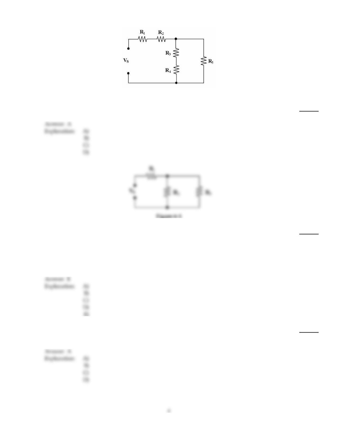
Figure 6–2
11)
If every resistor in Figure 6–2 equals 2.2 k, what is the value of RT?
11)
A)
5.87 k
B)
2.2 k
C)
4.4 k
D)
5.5 k
12)
In Figure 6–1, R1 is connected in ________.
12)
A)
parallel with R3
B)
parallel with R2
C)
series with R3
D)
series with R2
E)
none of the above
13)
Two series 1 k resistors are connected in parallel with a 2.2 k resistor. If the voltage across one
of the 1 k resistors is 6 V, what is the voltage across the 2.2 k resistor?
13)
A)
12 V
B)
6 V
C)
3 V
D)
13.2 V
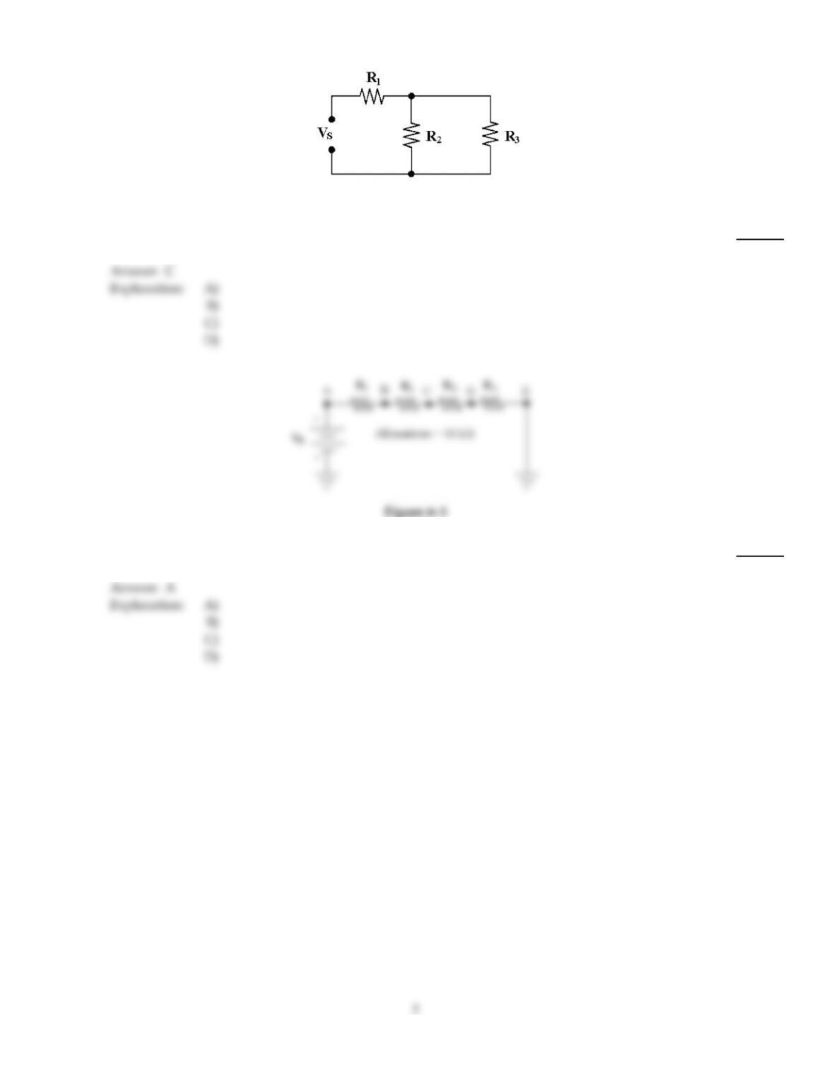
Figure 6–1
14)
If R1= 4.7 k, R2= 3.3 k and R3= 1 k in Figure 6–1, the total resistance equals ________.
14)
A)
660
B)
5700
C)
5467
D)
4125
15)
If VR3 = 17 V in Figure 6–3, what is the value of P1?
15)
A)
28.9 mW
B)
2.89 W
C)
1.7 mW
D)
17 mW
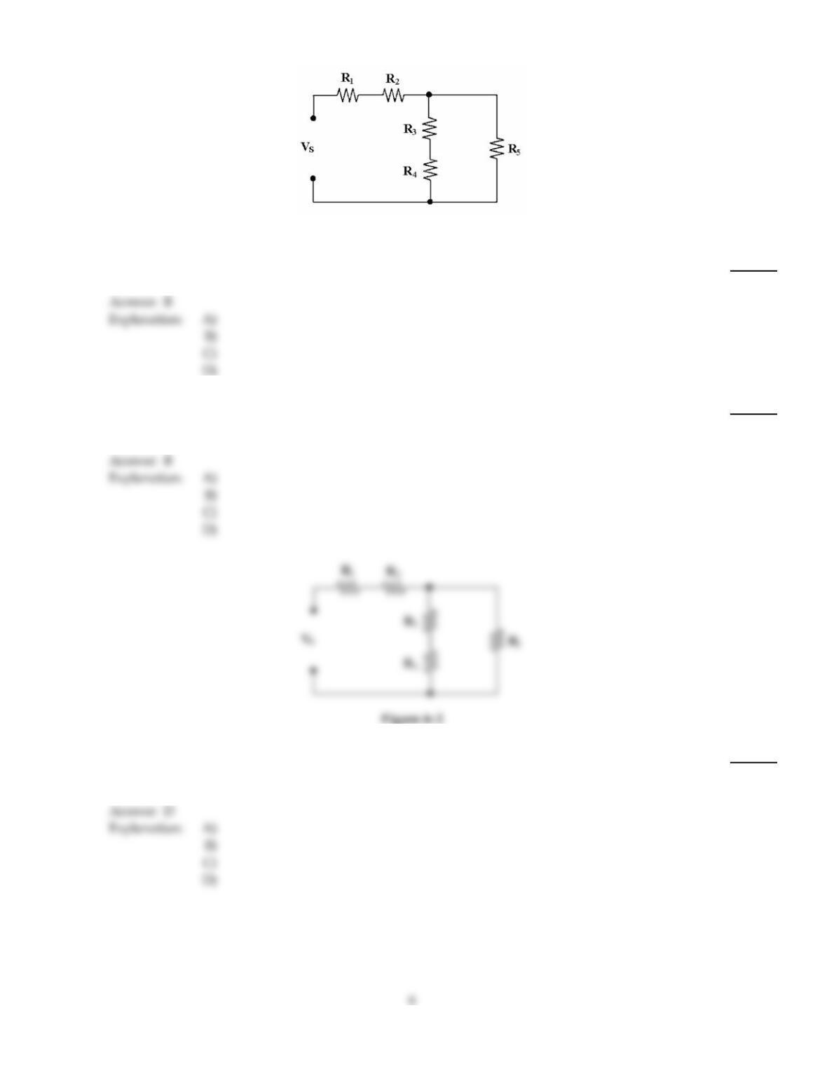
Figure 6–2
16)
If all resistors equal 4.7 k and Vs equals 20 V in Figure 6–2, what is the value of IR3?
16)
A)
1.06 mA
B)
0.53 mA
C)
11.99 mA
D)
12.5 mA
17)
If a voltage divider consists of two 10 k resistors, which one of these load resistors will change the
output voltage the most?
17)
A)
20 k
B)
10 k
C)
100 k
D)
1 M
18)
If R4 shorts in Figure 6–2, VR5 ________.
18)
A)
decreases to zero
B)
remains the same
C)
increases
D)
decreases
19)
If R3 shorts in Figure 6–2, VR5 ________.
19)
A)
decreases
B)
remains the same
C)
increases
20)
If four parallel 10 k resistors are connected in series with a single 20 k resistor and one of the
parallel resistors opens, how does the voltage across the other parallel resistors change?
20)
A)
It increases.
B)
It remains the same.
C)
It decreases.
21)
If Vs= 40 V and R3 opens in Figure 6–3, what is the value of VR3?
21)
A)
10 V
B)
40 V
C)
20 V
D)
0 V
E)
30 V
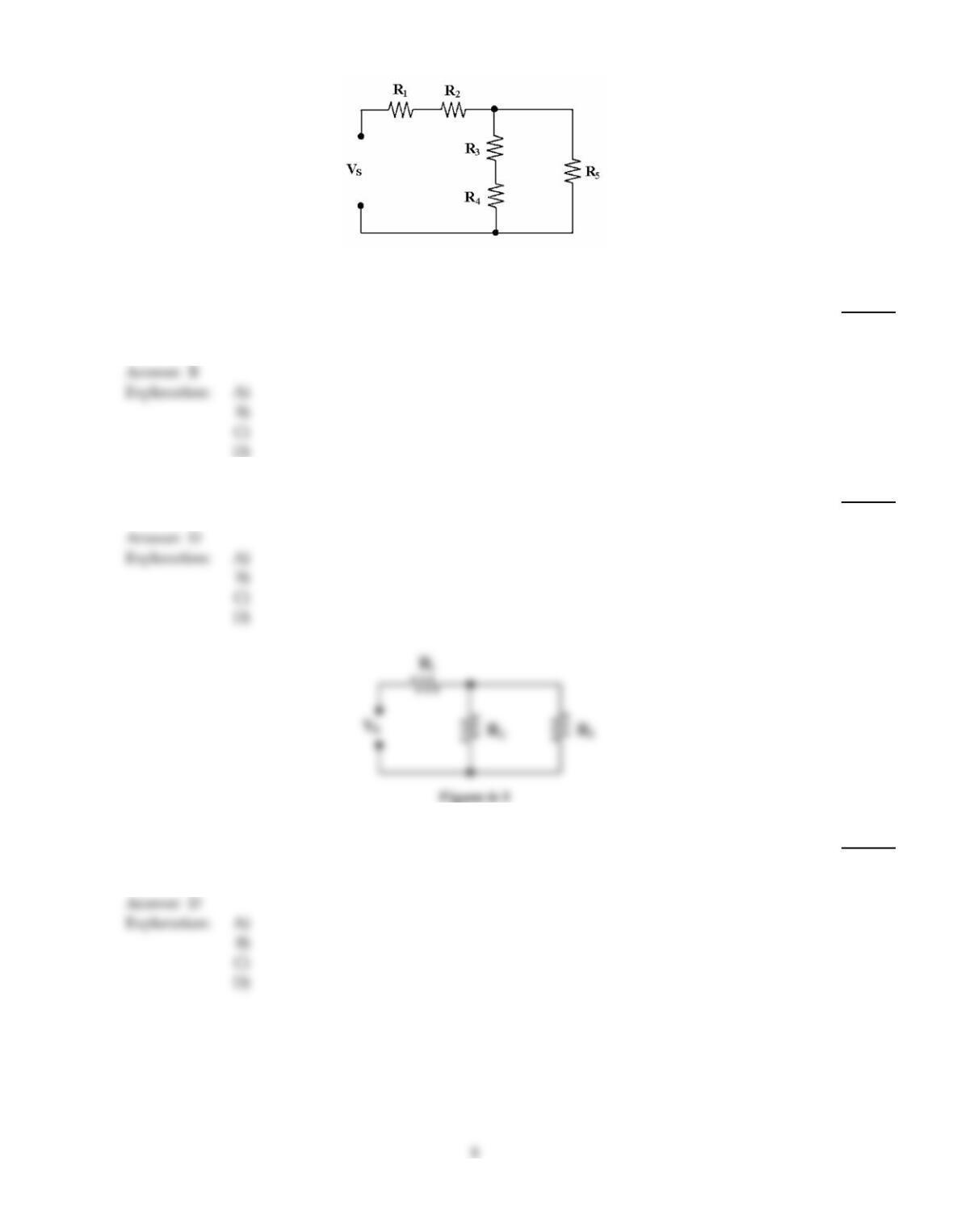
Figure 6–2
22)
If R1 shorts in Figure 6–2, VR4 ________.
22)
A)
decreases
B)
increases
C)
equals VR2
D)
remains the same
23)
If Vs= 15 V and every resistor equals 2.2 k in Figure 6–2, what is the value of IR4?
23)
A)
0.42 mA
B)
5.11 mA
C)
2.55 mA
D)
0.85 mA
24)
If R3 opens in Figure 6–1, VR1 ________.
24)
A)
increases
B)
decreases to zero
C)
remains the same
D)
decreases
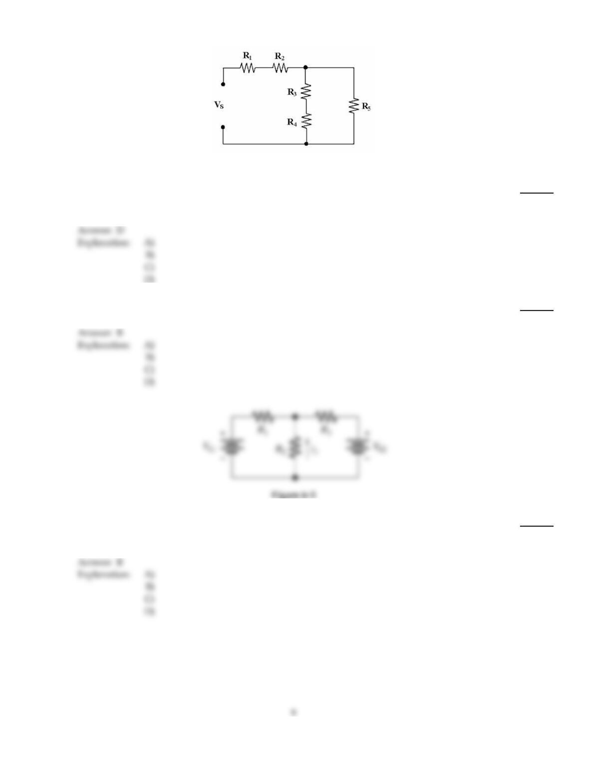
Figure 6–2
25)
In Figure 6–2, R3 and R4 are connected in ________.
25)
A)
series with each other and R5
B)
parallel with R1 and R2
C)
series with each other and R1 and R2
D)
series with each other
26)
In Figure 6–2 if R1= 10 k, R2= 4.7 k, R3= 4.7 k, R4= 10 k and R5= 4.7 k, RT= ?
26)
A)
0
B)
18.3 k
C)
6.1 k
D)
24.7 k
27)
Refer to Figure 6–5. If all of the resistors of this circuit are 5 k and VS1 and VS2 are 10 V but
opposing polarities, what would be the current flow through R2?
27)
A)
1.33 mA
B)
0 A
C)
13.33 mA
D)
2.66 mA
28)
Power in a series–parallel resistor circuit is dissipated as:
28)
A)
voltage loss.
B)
heat.
C)
current flow.
D)
resistance change.
29)
In solving series–parallel circuits, the last and easiest to solve for is:
29)
A)
PT.
B)
IT.
C)
RT.
D)
ET.
A
30)
What is the resistance between points B and E in Figure 6–3?
30)
A)
10 k
B)
30 k
C)
20 k
D)
40 k
B
31)
In the parallel portion of series–parallel circuits, the total resistance is:
31)
A)
greater than the largest resistance.
B)
less than the smallest resistance.
C)
equal to the smallest resistance.
D)
less than any one resistance.
B
B
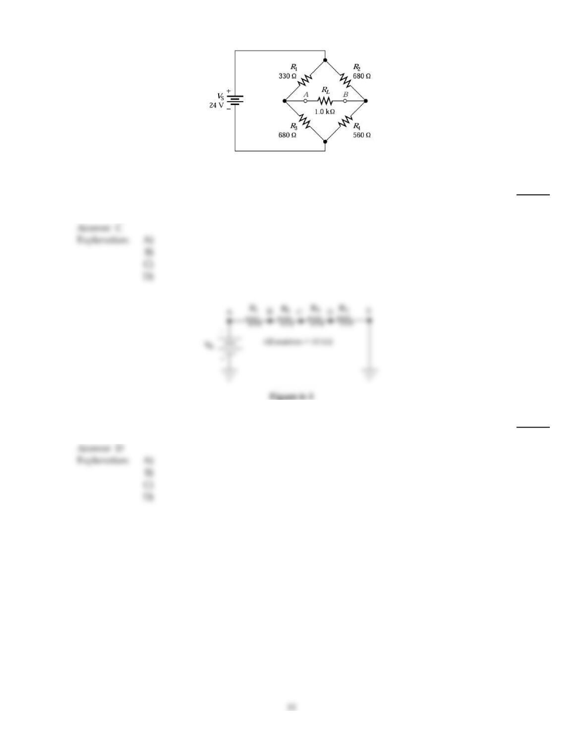
Figure 6–4
32)
Refer to Figure 6–4. What approximate R1 resistor value would it take to balance this bridge
circuit?
32)
A)
680
B)
560
C)
825
D)
330
33)
What is the resistance between points A and D in Figure 6–3?
33)
A)
40 k
B)
20 k
C)
10 k
D)
30 k
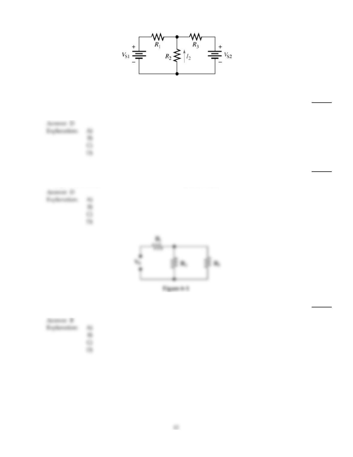
Figure 6–5
34)
Refer to Figure 6–5. Determine the amount of current flow through R2 with the following
component parameters. VS1 = 10 V, VS2 = 3 V, R1 = 2 k, R2 = 3 k, and R3 = 700
34)
A)
5.3 mA
B)
1 mA
C)
0 A
D)
1.37mA
35)
One Ohm’s law formula PT= P1+ P2+ etc. can be used to solve for total power in:
35)
A)
series circuits.
B)
series–parallel circuits.
C)
parallel circuits.
D)
all of these.
36)
If Vs= 20 V, R1= 10 k, R2= 50 k and R3= 15 k in Figure 6–1, PR2 equals ________.
36)
A)
7.64 mW
B)
2.30 mW
C)
8.63 mW
D)
18.6 mW