Exam
Name___________________________________
MULTIPLE CHOICE. Choose the one alternative that best completes the statement or answers the question.
1)
The voltage drop across any resistor or combination of resistors in a series circuit equals:
1)
A)
the product of the circuit current times the resistance value.
B)
the ratio of the resistance values to the total resistance times the source voltage.
C)
the applied voltage across the resistor (A).
D)
all of these.
2)
Four resistors are connected in series across an 18 V source. Three resistors drop 0 V and one
resistor drops 18 V. What’s the trouble?
2)
A)
The three resistors are open.
B)
Two of the resistors are shorted.
C)
One resistor is open.
D)
There is no trouble; these voltages are normal.
C
3)
Two 100 k resistors are wired in series across a 20 V source. How much voltage does each resistor
drop?
3)
A)
100 mA
B)
100 k
C)
10 V
D)
20 V
C
4)
Based upon electron current flow, the polarity on the side of the resistor where current enters is
________. The polarity on the side of the resistor where current exits is ________.
4)
A)
negative, negative
B)
positive, negative
C)
negative, positive
D)
positive, positive
C
D
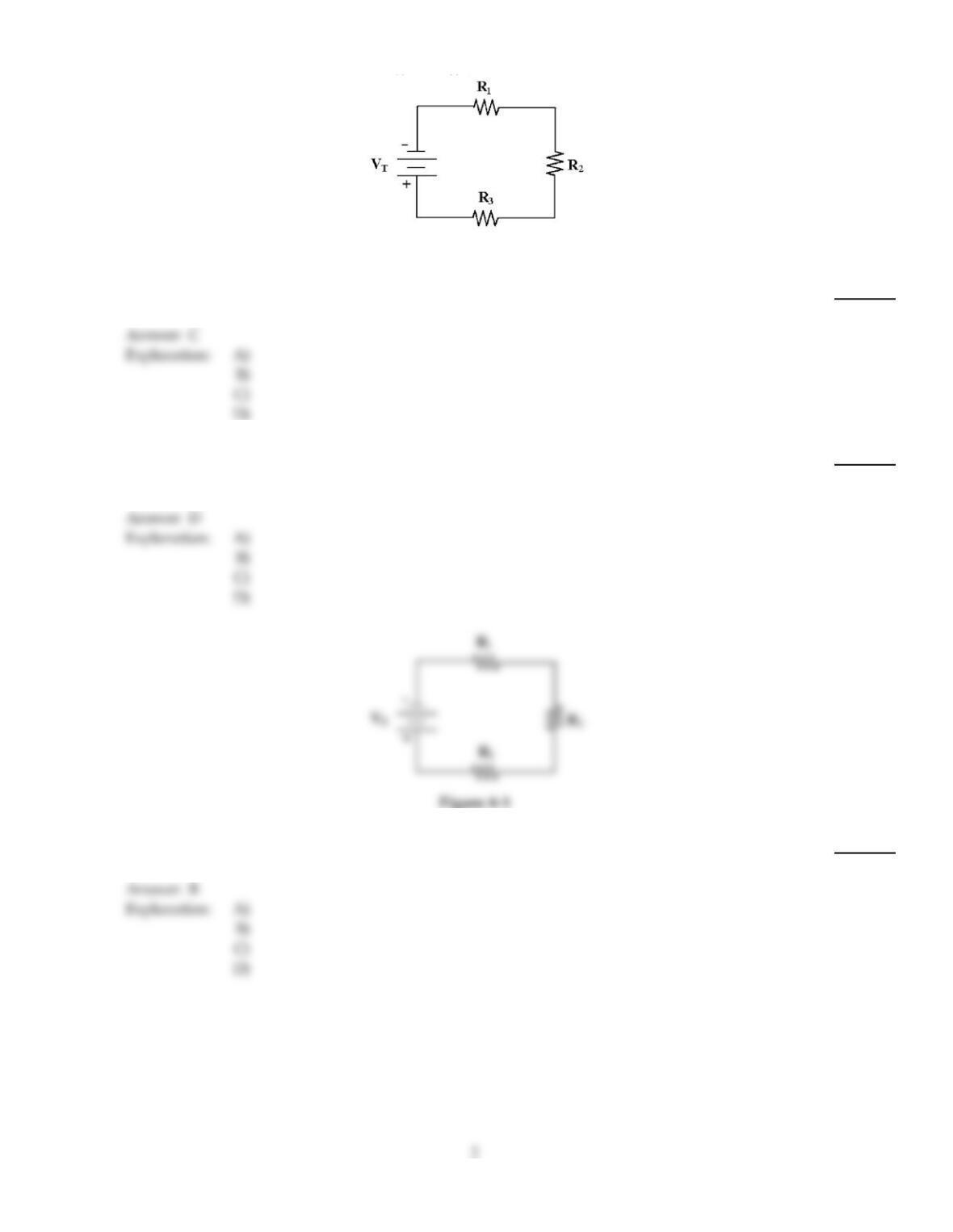
Figure 4–1
5)
Calculate VT in Figure 4–1 if R1= 4.7 k, VR1 = 10 V, R2= 4.7 k and R3= 4.7 k.
5)
A)
4.7 V
B)
10 V
C)
30 V
D)
14.7 V
6)
An open in a series circuit results in:
6)
A)
no power dissipation.
B)
no current flow.
C)
source voltage appearing across the open.
D)
all of these.
Figure 4–1
7)
What is the total resistance in Figure 4–1 if R1= 10 k, R2= 10 k and R3= 15 k?
7)
A)
0 k
B)
35 k
C)
25 k
D)
infinite
8)
One of the most popular applications of a potentiometer is as an adjustable voltage divider also
known as a:
8)
A)
divider control.
B)
voltage control.
C)
volume control.
D)
current control.
9)
How much voltage is dropped across R2 and R3 in Figure 4–1 if R1= 4.7 k, VR1 = 10 V, R2= 4.7
k and R3= 4.7 k?
9)
A)
VR2 = 10 V, VR3 = 4.7 V
B)
VR2 = 4.7 V, VR3 = 10 V
C)
VR2 = 10 V, VR3 = 10 V
D)
VR2 = 14.7 V, VR3 = 14.7 V
10)
A 500 k potentiometer is connected across a 5 V source. If the voltage from the wiper to the lower
end of the potentiometer is 1.2 V, what is the resistance of that lower part?
10)
A)
0
B)
380 k
C)
120 k
D)
500 k
11)
What is the total supply voltage if 16 V and 12 V sources are wired in series opposing?
11)
A)
28 V
B)
12 V
C)
4 V
D)
16 V
12)
A 22 k and 12 k resistor are connected across a 68 V source. How is the voltage divided?
12)
A)
34 V and 34 V
B)
22 V and 12 V
C)
44 V and 24 V
D)
68 V and 68 V
13)
If a 4.7 k, 5.6 k and 10 k resistor are in series, which resistor drops the most voltage?
13)
A)
the 10 k resistor
B)
the 5.6 k resistor
C)
the 4.7 k resistor
D)
That can’t be determined from the given information.
14)
In a series circuit, total power PT is calculated as:
14)
A)
P1× P2× P3× etc.
B)
P1+ P2+ P3+ etc.
C)
1/P1+ 1/P2+ 1/P3+ etc.
D)
P1÷ P2÷ P3÷ etc.
15)
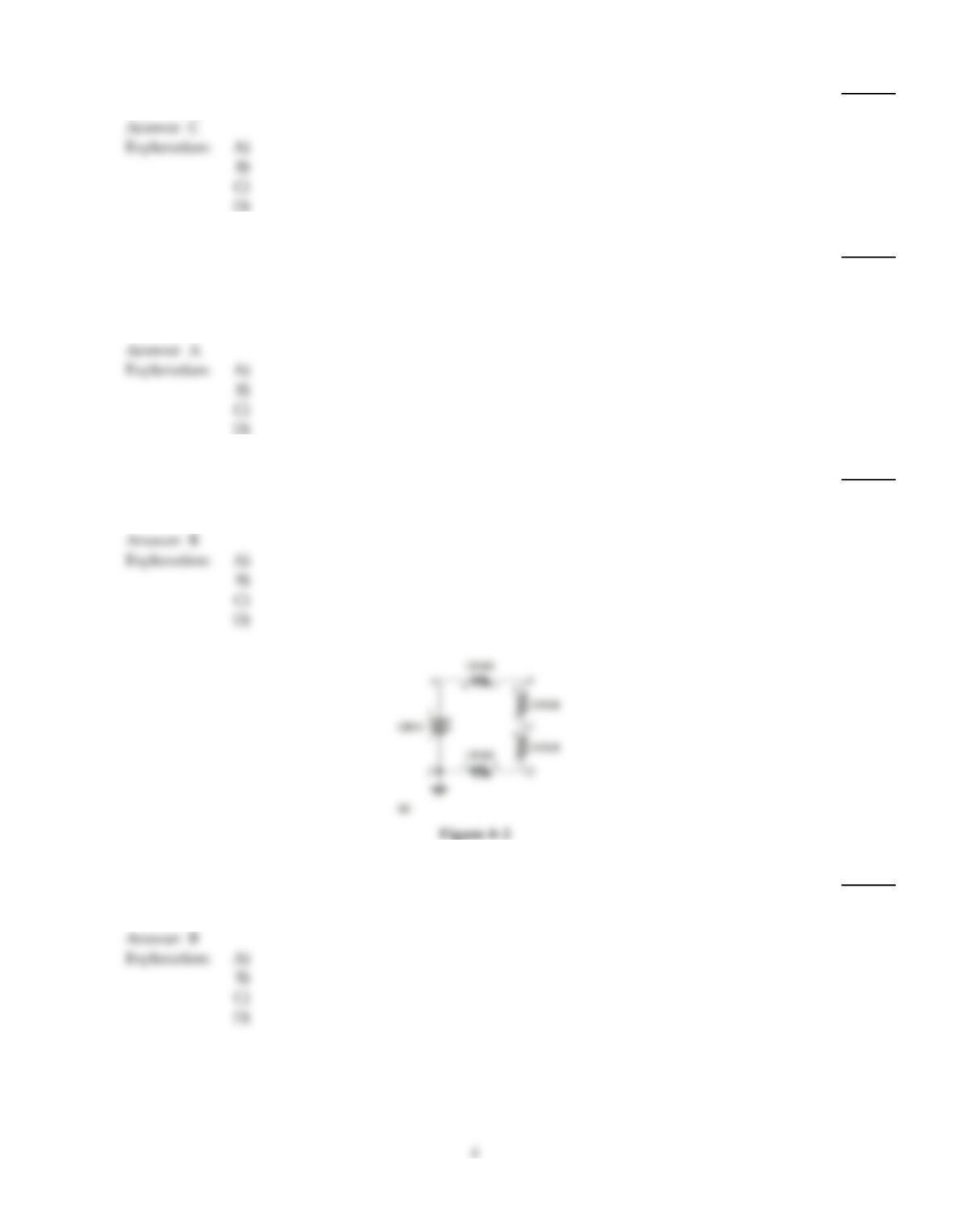
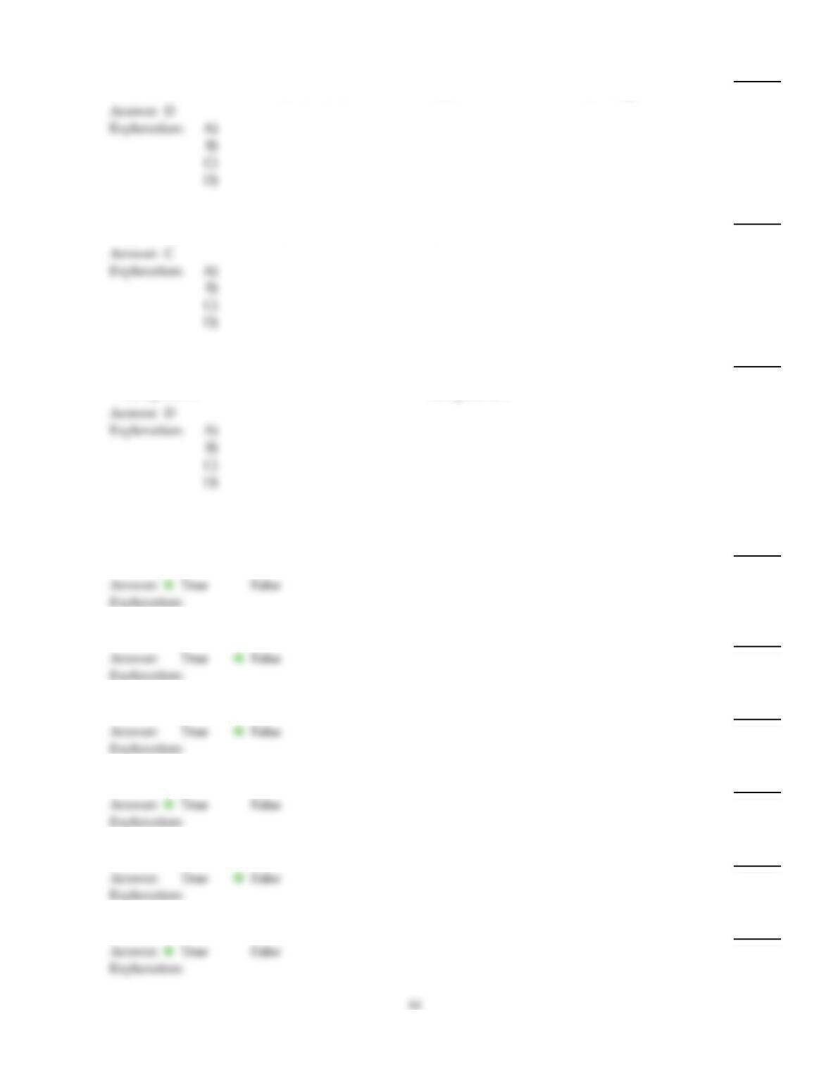
Refer to Figure 4–2a. Voltage B to ground is less than normal. What could be the cause of failure?
15)
A)
short between A and B
B)
short between E and D
C)
open between B and C
D)
open between C and D
16)
If 12 V and 17 V sources are wired in series aiding, what is the total supply voltage?
16)
A)
17 V
B)
29 V
C)
5 V
D)
12 V
17)
Three resistors are connected in series across a 60 V source. If VR1 = 19 V and VR2 = 14.3 V, then
what is the voltage drop across R3?
17)
A)
14.3 V
B)
26.7 V
C)
45.7 V
D)
19 V
18)
What type of resistor could be used as variable voltage–divider?
18)
A)
thermistor
B)
potentiometer
C)
rheostat
D)
any one of the above
19)
Calculate VR3 in Figure 4–1 if VT= 50 V, VR1 = 19.7 V and VR2 = 2.7 V.
19)
A)
30.3 V
B)
47.3 V
C)
27.6 V
D)
22.4 V
20)
Four series resistors are connected across a 30 V source and carry 0.125 mA. If R1= 10 k, R2= 33
k and R3= 47 k, what is the value of R4?
20)
A)
15 k
B)
150 k
C)
1.5 k
D)
150
21)
Calculate VT in Figure 4–1 if VR1 = 16 V, R1= 10 k, R2= 10 k and R3= 15 k.
21)
A)
56 V
B)
112 V
C)
16 V
D)
24 V
22)
If 5 V and 16 V power supplies are connected in series aiding, what is the total voltage?
22)
A)
21 V
B)
24 V
C)
80 V
D)
16 V
23)
When 50 V is applied to four series resistors, 100 µA flows. If R1= 12 k, R2= 47 k and R3= 56 k
, what is the value of R4?
23)
A)
3.85 M
B)
3.85 k
C)
385 k
D)
38.5 k
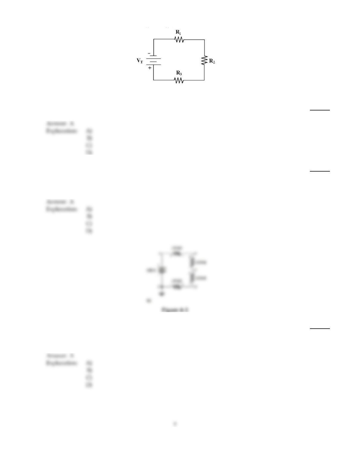
Figure 4–1
24)
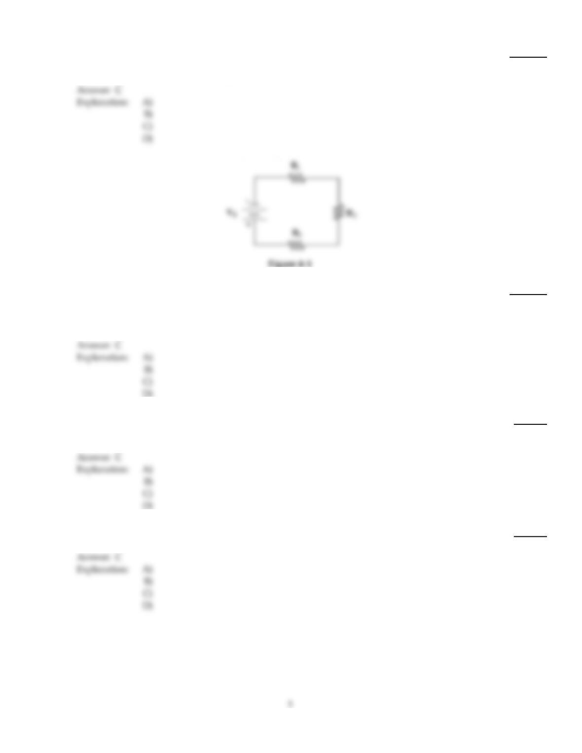
Calculate IT in Figure 4–1 if R1= 4.7 k, VR1 = 10 V, R2= 4.7 k and R3= 4.7 k.
24)
A)
2.13 mA
B)
4.26 mA
C)
6 mA
D)
1 mA
25)
If R1= 12 k and R2= 5 k and they are wired in series across a 20 V source, what is VR1 and
VR2?
25)
A)
VR1 = 14.12 V, VR2 = 5.88 V
B)
VR1 = 10 V, VR2 = 10 V
C)
VR1 = 0 V, VR2 = 20 V
D)
VR1 = 5.88 V, VR2 = 14.12 V
26)
Refer to Figure 4–2a. The resistor between points E and D looks charred. What most likely would
cause this?
26)
A)
short between A and D
B)
open A and the power supply
C)
short between A and B
D)
Any of these could cause this problem.
27)
If a 10 k and 5 k resistor are connected in series across a 12 V source, the voltage across the 10 k
resistor is ________ and the voltage across the 5 k resistor is ________.
27)
A)
8 V, 4 V
B)
8 V, 8 V
C)
4 V, 4 V
D)
4 V, 8 V
28)
If five equal resistors dissipate a total of 10 W in a series circuit, how much power does each
resistor dissipate?
28)
A)
2 W
B)
50 W
C)
5 W
D)
10 W
29)
A 50 k potentiometer is connected across a 15 V source. If the voltage from the wiper to the lower
end of the potentiometer is 3.2 V, what is the resistance of that lower part?
29)
A)
0
B)
50 k
C)
10.7 k
D)
39.3 k
30)
If a 68 , 33 , 100 and 47 resistor are connected in series across a 9 V battery, the current
equals ________.
30)
A)
36.3 mA
B)
327 mA
C)
27.6 A
D)
22.3 mA
31)
A short in a series circuit results in:
31)
A)
increased circuit resistance.
B)
decreased or reduced current flow.
C)
increased or maximum current flow.
D)
decreased power consumption.
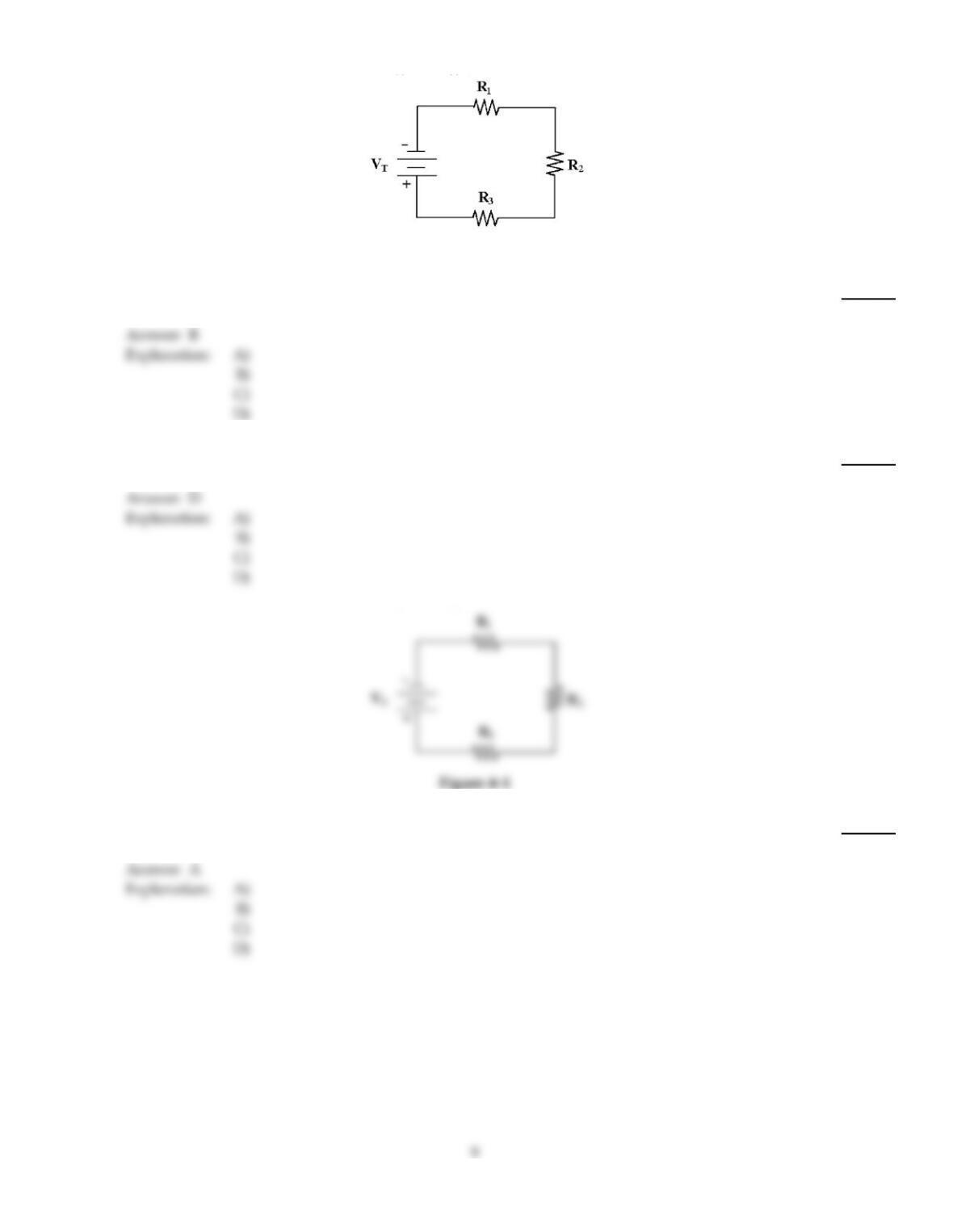
Figure 4–1
32)
Calculate the current in Figure 4–1 if VR1 = 16 V, R1= 10 k, R2= 10 k and R3= 15 k.
32)
A)
3.2 mA
B)
1.6 mA
C)
12 mA
D)
0 A
33)
If 18 V and 6 V sources are connected in series opposing, what is the total voltage?
33)
A)
18 V
B)
6 V
C)
2 V
D)
12 V
Figure 4–1
34)
Calculate PR2 in Figure 4–1 if VR1 =16 V, R1= 10 k, R2= 10 k and R3= 15 k.
34)
A)
25.6 mW
B)
0.0256 mW
C)
2.56 mW
D)
0.256 mW
35)
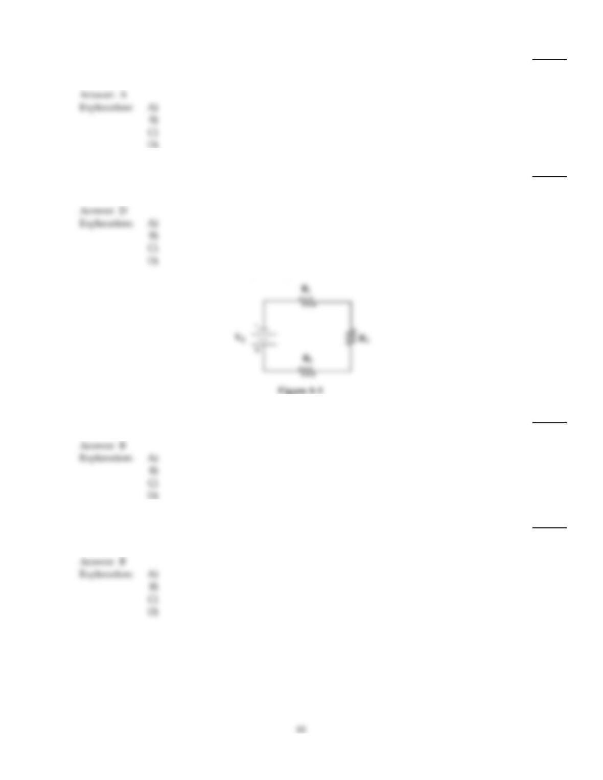
If R2 opens in Figure 4–1, the total power dissipated ________.
35)
A)
decreases to zero
B)
remains the same
C)
increases to maximum
D)
will depend upon the source voltage
36)
Circuit ground or chassis ground can be thought of as a:
36)
A)
common point.
B)
neutral connection point.
C)
reference point.
D)
all of these
37)
R1= 4.7 k, R2= 4.7 k and R3= 4.7 k in Figure 4–1. What is RT if R2 shorts?
37)
A)
0
B)
9.4 k
C)
4.7 k
D)
infinite
38)
If –12 V and –6 V are connected so they equal –18 V, these sources are ________.
38)
A)
in parallel
B)
series aiding
C)
connected dangerously
D)
series opposing
39)
Two resistors are in series across a 12 V source. If each resistor equals 470 k, what is the voltage
across each resistor?
39)
A)
6 V
B)
12 V
C)
9 V
D)
3 V
40)
In a series circuit, the largest amount of power is dissipated by:
40)
A)
the smallest resistor.
B)
the largest resistor.
C)
the first resistor.
D)
any resistor, since the current is the same throughout the circuit.
41)
If R2 shorts in Figure 4–1, the total circuit power ________.
41)
A)
decreases
B)
depends upon the source voltage
C)
remains the same
D)
increases
42)
If three 2.2 k resistors are connected in series across a 50 V source, PT equals ________.
42)
A)
104.2 mW
B)
52.08 mW
C)
379 mW
D)
402 mW
43)
If a 100 , 220 , and 330 resistor are connected in series, total resistance equals ________.
43)
A)
less than 100
B)
1650
C)
650
D)
the average of the three values
44)
Calculate VR2 and VR3 in Figure 4–1 if VR1 = 16 V, R1= 10 k, R2= 10 k and R3= 15 k.
44)
A)
VR2 = 16 V, VR3 = 16 V
B)
VR2 = 16 V, VR3 = 24 V
C)
VR2 = 24 V, VR3 = 12 V
D)
VR2 = 16 V, VR3 = 12 V
45)
If 12 V and –19 V sources are connected so their total voltage is –7 V, they are ________.
45)
A)
in parallel
B)
connected dangerously
C)
series aiding
D)
series opposing
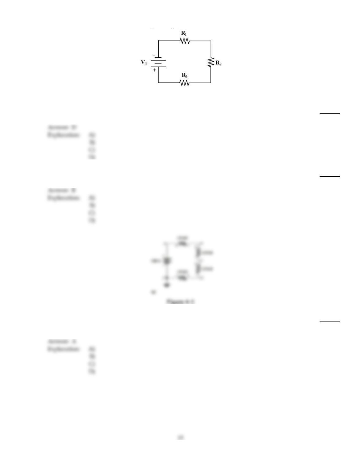
Figure 4–1
46)
VR1 = 16 V, R= 10 k, R2= 10 k and R3= 15 k in Figure 4–1. If R2 opens, then RT is ________.
46)
A)
25 k
B)
0
C)
10 k
D)
infinite
47)
Calculate PT in Figure 4–1 if VT= 100 V and all three resistors are each 47 k.
47)
A)
22 W
B)
70.9 mW
C)
709 mW
D)
23.6 mW
48)
Refer to Figure 4–2a. Voltage from C to ground is 100 V. What is the probable cause of failure?
48)
A)
open between E and D
B)
open between A and B
C)
short between A and B
D)
voltage reading is normal
49)
What is the easiest, most practical measurement performed during troubleshooting?
49)
A)
current
B)
resistance
C)
power
D)
voltage
50)
–1.2 V, +5 V and +6 V batteries are connected in series. The total voltage is ________.
50)
A)
12.2 V
B)
1.3 V
C)
9.8 V
D)
1.2 V
51)
If each of the six resistors in a series circuit drops 5 V, the source voltage ________.
51)
A)
depends on the current
B)
depends on the resistor values
C)
equals 5 V
D)
equals 30 V
TRUE/FALSE. Write ‘T’ if the statement is true and ‘F’ if the statement is false.
52)
According to Kirchhoff’s Voltage Law, the sum of the individual voltage drops in a series circuit
equals the source voltage.
52)
53)
Voltage sources in series increase both voltage and current capacity.
53)
54)
If a resistor is dissipating 1/4 W, it can supply 1/4 W to the load.
54)
55)
Three 2 V cells in series with one in series–opposing would yield 2 V.
55)
56)
If a 1/4 W resistor and a 1/2 W resistor are wired in series, they can safely dissipate 3/4 W.
56)
57)
If a resistor is rated at 1/2 W, it can safely dissipate 0.325 W.
57)
58)
Kirchhoff’s Voltage Law states that the algebraic sum of all the voltages around a closed path is zero.
58)
59)
A series circuit has multiple current paths.
59)
60)
If 4.7 k, 2.2 k and 1.2 k resistors are wired in series, the total resistance is 8.7 k.
60)
61)
In a series circuit, the current is the same at every point in the circuit.
61)
62)
The total power dissipated in a series circuit equals the sum of the individual powers.
62)
63)
Calculating current for a series resistor circuit can be accomplished with a measured voltage across
one of the resistors divided by that resistor’s value.
63)
64)
Total power dissipated in a series circuit equals source voltage multiplied by current.
64)
65)
If 6.8 k, 1.2 k and 5.6 k resistors are wired in series, the total resistance is 13.6 k.
65)

Answer Key
Testname: C4
16
Answer Key
Testname: C4
17