Exam
Name___________________________________
MULTIPLE CHOICE. Choose the one alternative that best completes the statement or answers the question.
1)
The turns ratio of a transformer (n) is defined as:
1)
A)
the number of turns in the primary divided by the number of turns in the secondary.
B)
the number of turns in the secondary divided by the number of turns in the primary.
C)
the number of turns in the secondary multiplied by the number of turns in the primary.
D)
the number of turns in the primary multiplied by the number of turns in the secondary.
2)
What is the secondary voltage in Figure 14–1 if the turns ratio is 4.5:1?
2)
A)
5.92 V
B)
4.72 V
C)
26.7 V
D)
540 V
3)
How can the windings ratio be safely determined for an unmarked transformer?
3)
A)
Standardized wire color codes indicate windings ratio.
B)
The turns ratio is the same as the ratio of primary resistance to secondary resistance ratio.
C)
Apply known low voltage ac to the primary and measure the secondary output. The ratio of
the voltages is the same as the windings ratio.
D)
either A or C
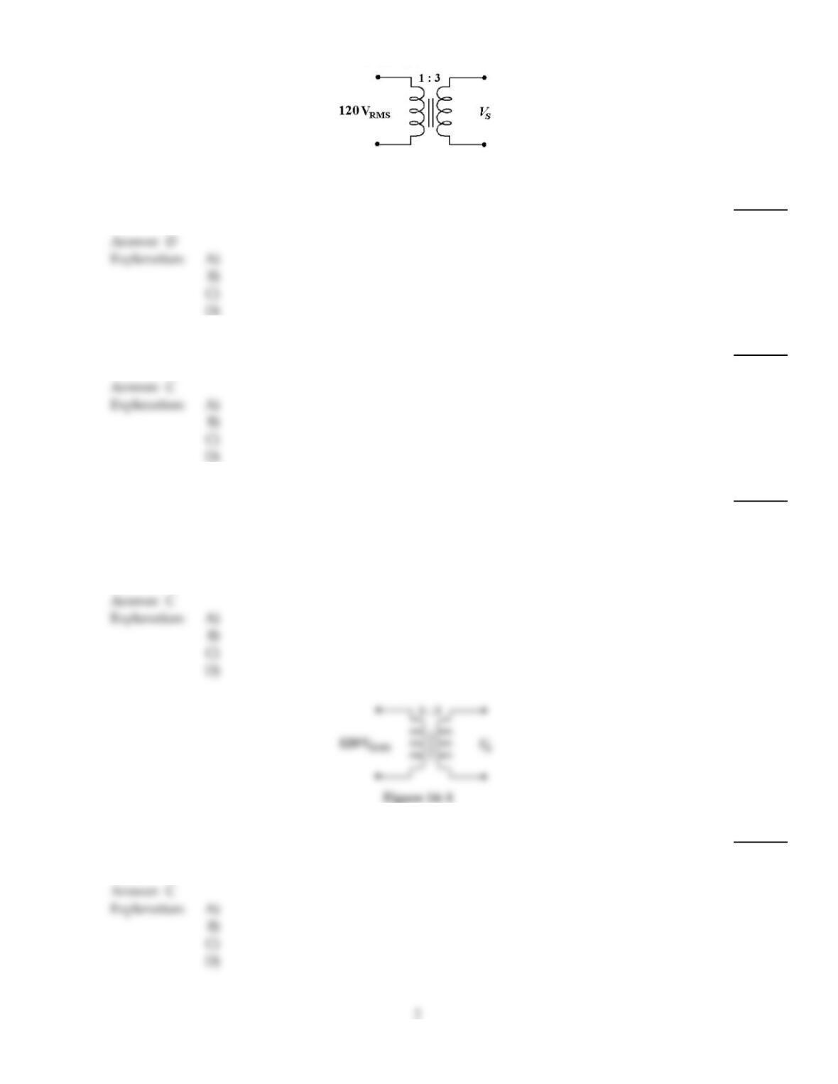
Figure 14–1
4)
In Figure 14–1, if the primary to secondary turns ratio is 7.5:1, the output voltage equals ________.
4)
A)
32 VRMS
B)
9 VRMS
C)
900 VRMS
D)
16 VRMS
5)
What is the secondary voltage in Figure 14–1 if the turns ratio is 7:1?
5)
A)
420 VRMS
B)
8.59 VRMS
C)
17.1 VRMS
D)
840 VRMS
C
6)
What is the likeliest way to fix a center–tapped transformer which outputs unequal voltages on
each half of the secondary?
6)
A)
Remove some turns from the half with the higher voltage winding.
B)
Add some turns to the half with the lower voltage winding.
C)
Replace the transformer.
D)
Do not concern yourself; the customer will probably not notice the problem.
C
Figure 14–1
7)
What is the reflected resistance seen by the primary in Figure 14–1 if the turns ratio is 3:1 and IS is
240 mA?
7)
A)
500
B)
167
C)
1500
D)
9000
C
D
8)
To couple two circuits together with no change in either voltage or current, use ________.
8)
A)
an isolation transformer
B)
a step–up transformer
C)
a step–down transformer
D)
a power transformer
9)
An autotransformer differs from most transformers in that:
9)
A)
source current flows through both the windings.
B)
it does not isolate the primary voltage from the secondary voltage.
C)
primary and secondary windings are the same.
D)
all of these.
D
10)
When the turns ratio of a transformer is 1:10 and the primary AC voltage in 6 V, then the secondary
voltage is ________.
10)
A)
36 V
B)
60 V
C)
6 V
D)
0.6 V
B
11)
The hysteresis loss in a transformer is ________.
11)
A)
caused by rapid reversal of the magnetic field
B)
another name for flux leakage loss
C)
caused by current flowing in the core
D)
caused by the resistance of the wire
A
A
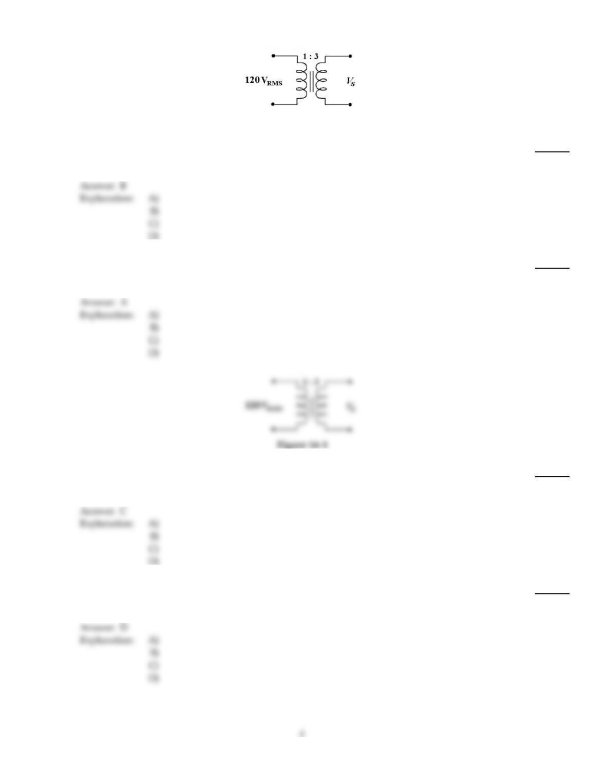
Figure 14–1
12)
In Figure 14–1, if the secondary current is 50 mA, the reflected resistance seen by the primary
equals ________.
12)
A)
7.2 k
B)
800
C)
2.4 k
D)
14.4 k
13)
When a 1 k load resistor is connected across the secondary winding of a transformer with a turns
ratio of 1:2, the source “sees” a reflected load of ________.
13)
A)
250
B)
2 k
C)
1 k
D)
4 k
Figure 14–1
14)
In Figure 14–1, the primary to secondary turns ratio is changed to 2.5:1 and the secondary current
equals 100 mA. What is the reflected resistance seen by the primary?
14)
A)
2.5 k
B)
5 k
C)
3 k
D)
1.2 k
15)
In Figure 14–1, if there are five times more turns in the primary than in the secondary, then what is
the secondary voltage?
15)
A)
120 V
B)
12 V
C)
600 V
D)
24 V
16)
The reflected load in a transformer is defined as the actual load as it appears to the source and
results from:
16)
A)
the current ratio.
B)
the voltage ratio.
C)
the turns ratio.
D)
the power ratio.
17)
What is the secondary current in Figure 14–1 with a 50 load resistor and 4:1 turns ratio?
17)
A)
1.66 A
B)
4.8 A
C)
9.6 A
D)
600 mA
18)
In Figure 14–1, if the secondary current is 50 mA, the primary current is ________.
18)
A)
50 mA
B)
48.7 mA
C)
300 mA
D)
150 mA
19)
What is the primary current in Figure 14–1 if IS= 40 mA and the turns ratio equals 4:1 ?
19)
A)
10 mA
B)
160 mA
C)
4 mA
D)
40 mA
20)
For a transformer to operate properly, it must:
20)
A)
work within its voltage, current and power ratings.
B)
be supplied with the proper AC signal.
C)
be connected to a load.
D)
all of these.
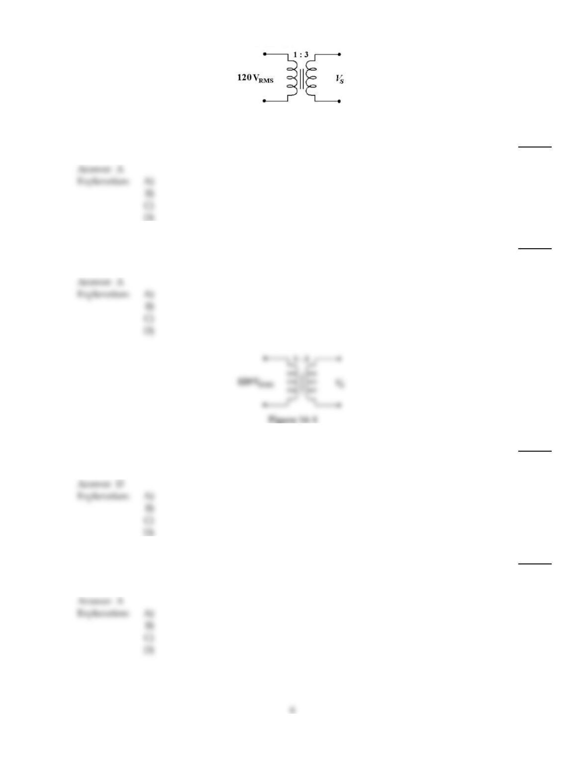
Figure 14–1
21)
What is the primary current in Figure 14–1 if the turns ratio equals 1:3 and IS equals 240 mA?
21)
A)
720 mA
B)
1.2 A
C)
60 mA
D)
120 mA
22)
A matching transformer’s primary needs ________ more turns than its secondary to match a 600
audio signal distribution line to an 8 speaker.
22)
A)
8.66
B)
0.013
C)
75
D)
0.115
Figure 14–1
23)
In Figure 14–1, if a load resistor of 75 is placed in the secondary circuit, what is the secondary
current?
23)
A)
5.33 A
B)
16 A
C)
533 mA
D)
4.8 A
24)
The relationship for the voltage ratio (Vsec/Vpri) in a transformer is:
24)
A)
the same as the turns ratio (Nsec/Npri).
B)
opposite to the turns ratio (Nsec/Npri).
C)
more than the turns ratio (Nsec/Npri).
D)
less than the turns ratio (Nsec/Npri).
25)
If a 12 V battery is connected across the primary of a transformer with a turns ratio of 1:4, then the
secondary voltage is ________.
25)
A)
0 V
B)
48 V
C)
3 V
D)
12 V
26)
An air core transformer would most likely be used for:
26)
A)
isolation.
B)
impedance matching
C)
audio frequencies
D)
radio frequencies.
D
27)
A step–up transformer will increase ________ and decrease ________.
27)
A)
voltage, impedance
B)
power, current
C)
voltage, power
D)
current, impedance
A
28)
Eddy current loss in a transformer is ________.
28)
A)
another name for flux leakage loss
B)
caused by rapid reversal of the magnetic field
C)
caused by the resistance of the wire
D)
due to current flowing in the core
D
A
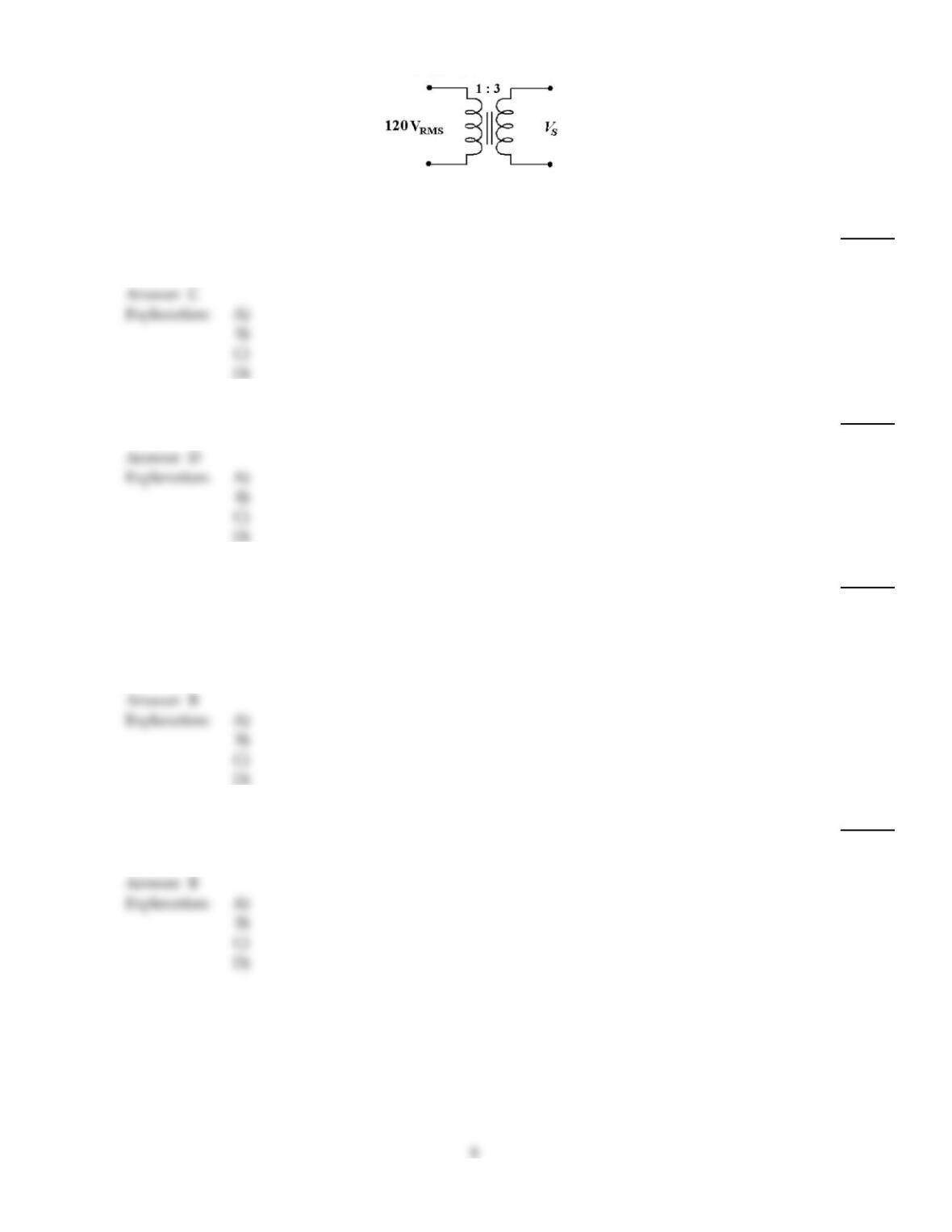
Figure 14–1
29)
What is the reflected resistance seen by the primary in Figure 14–1 if the turns ratio is 4:1 and IS is
40 mA?
29)
A)
16 k
B)
4 k
C)
12 k
D)
8 k
30)
What is the secondary voltage in Figure 14–1 if the turns ratio is 9:1?
30)
A)
106 V
B)
53.2 V
C)
26.6 V
D)
13.3 V
31)
In Figure 14–1, the primary to secondary turns ratio is 1:3 and the secondary current equals 120
mA. What is the primary current?
31)
A)
180 mA
B)
360 mA
C)
40 mA
D)
cannot compute because the voltage is not given
32)
What type transformer most likely has a 1:1 turns ratio?
32)
A)
power
B)
isolation
C)
center tapped
D)
impedance matching
33)
The phrase “Maximum power is delivered to the load when the load resistance equals the source
resistance” is a definition of ________.
33)
A)
Ohm’s Law
B)
the maximum power transfer theorem
C)
Lenz’s Law
D)
Kirchhoff’s Law
34)
Which winding will have the lowest measured resistance in a transformer with four secondary
windings?
34)
A)
the 5 V secondary
B)
the 550 V secondary
C)
the 12 V secondary
D)
the 6.3 V secondary
35)
In Figure 14–1, if the primary to secondary turns ratio is 9:1 and a 1 k load resistor is placed in the
secondary, the reflected resistance seen by the primary equals ________.
35)
A)
1 k
B)
81 k
C)
162 k
D)
111
36)
What is the secondary voltage in Figure 14–1 if the turns ratio is 1:3?
36)
A)
240 VRMS
B)
360 VRMS
C)
40 VRMS
D)
80 VRMS
37)
A center tap transformer has a connection at the midpoint of the secondary winding resulting in:
37)
A)
secondary voltages half that of a non–center tapped transformer with the same turns ratio.
B)
two equal magnitude secondary voltages.
C)
two 180 degree out of phase secondary voltages.
D)
all of these.
38)
A step–up transformer will increase ________ and decrease ________.
38)
A)
current, impedance
B)
impedance, current
C)
current, voltage
D)
voltage, impedance
39)
The measured voltage on the secondary of a given transformer is 0 V. Which of the following could
have caused this?
39)
A)
shorted load
B)
open primary
C)
open secondary
D)
any of the above
40)
The turns ratio required to match a 50 source to a 200 load is ________.
40)
A)
1:2
B)
2:1
C)
4:1
D)
1:4
41)
The relationship for the current ration (Isec/Ipri) in a transformer is:
41)
A)
the inverse of the turns ratio (Nsec/Npri).
B)
the same as the turns ratio (Nsec/Npri).
C)
more than the turns ratio (Nsec/Npri).
D)
less than the turns ratio (Nsec/Npri).
42)
If 10 W of power are applied to the primary of an ideal transformer with a turns ratio of 1:5, the
power delivered to the secondary load is ________.
42)
A)
0 W
B)
0.5 W
C)
10 W
D)
50 W
43)
Transformers ________.
43)
A)
match the impedance of a source to the impedance of a load
B)
convert a lower current into a higher current
C)
convert a higher voltage into a lower voltage
D)
all of these
44)
To match a 600 audio load to a 4 speaker system, the primary of the impedance matching
transformer must have ________ more turns than the secondary.
44)
A)
150
B)
3.06
C)
12.2
D)
The primary should have less turns than the secondary.
45)
The relationship for the impedance matching ratio (RL/Rpri) in a transformer is:
45)
A)
equal to the turns ratio (Nsec/Npri).
B)
opposite to the turns ratio (Nsec/Npri).
C)
opposite to the turns ratio (Nsec/Npri) squared.
D)
equal to the turns ratio (Nsec/Npri) squared.
46)
36 V of dc is applied to a windings ratio of 1:2. What is the secondary voltage?
46)
A)
something slightly less than 72 V since transformers do have some loss
B)
72 V
C)
144 V
D)
none of the above
47)
What is the problem if a power transformer is delivering a low output voltage even though the
primary voltage is correct?
47)
A)
a shorted primary
B)
a partially shorted secondary
C)
an open secondary
D)
an open primary
48)
The small dot placed on schematics of transformers indicates:
48)
A)
the polarity of the voltages.
B)
the direction of the winding.
C)
the phase of the voltages.
D)
all of these.
49)
Although the input voltage to the transformer’s primary is correct, the transformer is outputting
zero volts. A probable trouble is ________.
49)
A)
a shorted primary
B)
an open primary
C)
a partially shorted primary
D)
a partially shorted secondary
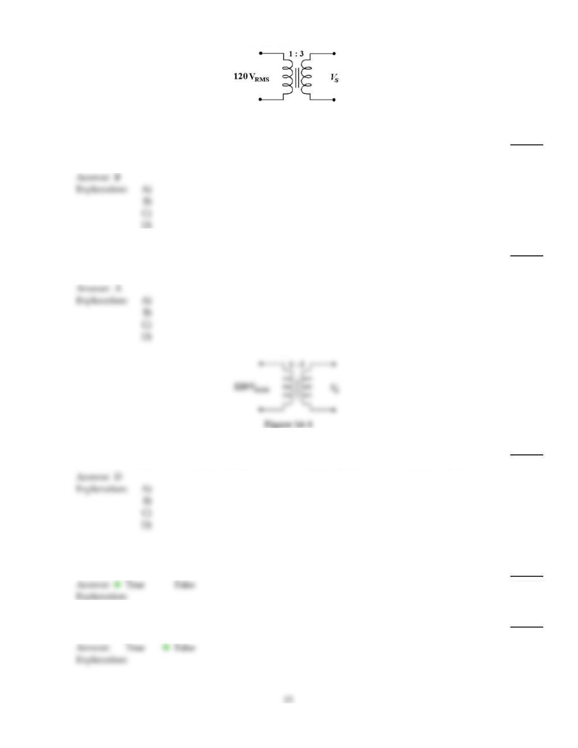
Figure 14–1
50)
In Figure 14–1, if the primary to secondary turns ratio is changed to 4:1 and a 1 k load resistor is
in the secondary, the secondary current equals ________.
50)
A)
480 mA
B)
30 mA
C)
120 mA
D)
240 mA
51)
When a 1 k load resistor is connected across the secondary winding of a transformer with a turns
ratio of 2:1, the source “sees” a reflected load of ________.
51)
A)
4 k
B)
500
C)
1 k
D)
2 k
Figure 14–1
52)
What is the secondary current in Figure 14–1 with a 100 load resistor and 3:1 turns ratio?
52)
A)
330 mARMS
B)
40 mARMS
C)
33 mARMS
D)
400 mARMS
TRUE/FALSE. Write ‘T’ if the statement is true and ‘F’ if the statement is false.
53)
An ideal transformer has no power loss.
53)
54)
Only the number of turns in the primary and secondary of a transformer determines the actual
secondary voltage.
54)
55)
A transformer with a turns ratio of 1:7 is a step down transformer.
55)
56)
A core material is not always necessary for proper operation of a transformer.
56)
57)
Transformer cores are made from laminated iron to reduce losses.
57)
58)
An ideal 10:1 transformer with 20 VA of power has less than 2 VA on the output.
58)
59)
Autotransformers cannot be used for isolation purposes since there is only one winding.
59)
60)
A step–down transformer could have a primary–secondary turns ratio of 4:1.
60)
61)
The efficiency of all transformers is very low.
61)
62)
If a dc voltage is input to a transformer’s primary, then an ac voltage is induced in its secondary.
62)
63)
A transformer with a turns ratio of 1:1 is often used to isolate a load from a source.
63)
64)
The impedance matching characteristic for a transformer is needed for a situation where maximum
power transfer to the load is desired.
64)
65)
A typical transformer fault would be an open winding.
65)
66)
The primary to secondary resistance should be relatively low.
66)

67)
A transformer can be used as an impedance matching device.
67)
Answer Key
Testname: C14
Answer Key
Testname: C14
17