Exam
Name___________________________________
MULTIPLE CHOICE. Choose the one alternative that best completes the statement or answers the question.
1)
The output voltage of a circuit at 70.7% of its maximum level measured in dB is:
1)
A)
–7 db.
B)
–3 dB.
C)
3 dB.
D)
7 dB.
2)
What is the current in a parallel RLC circuit if its impedance is 0.22 M, Q is 100 and VS= 50 V?
2)
A)
0.227 mA
B)
0.0227 mA
C)
2.27 mA
D)
22.7 mA
3)
The resonant frequency of a tank circuit with a 0.150 mH inductor and 300 pF capacitor is ________.
3)
A)
750 kHz
B)
347 kHz
C)
6.05 MHz
D)
1.65 MHz
4)
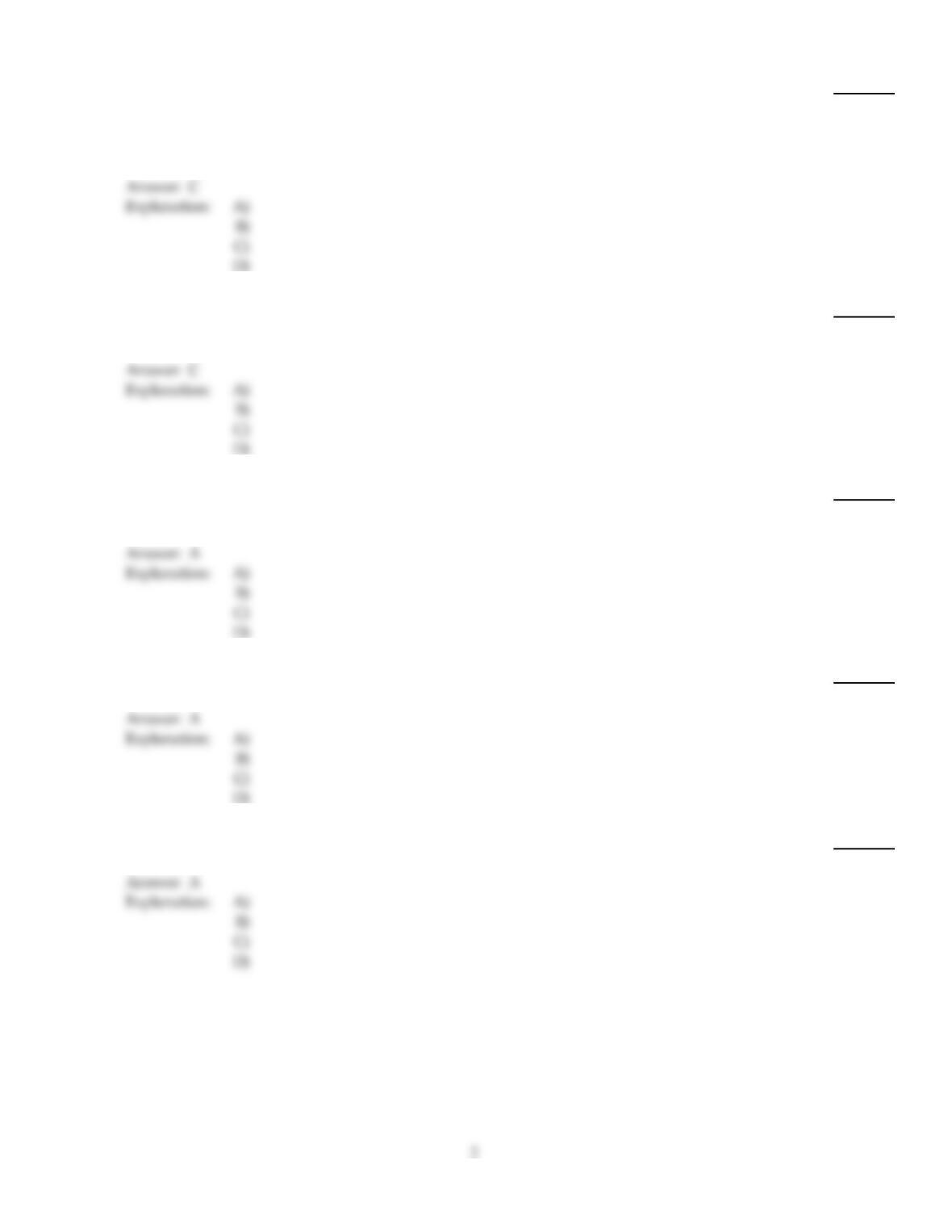
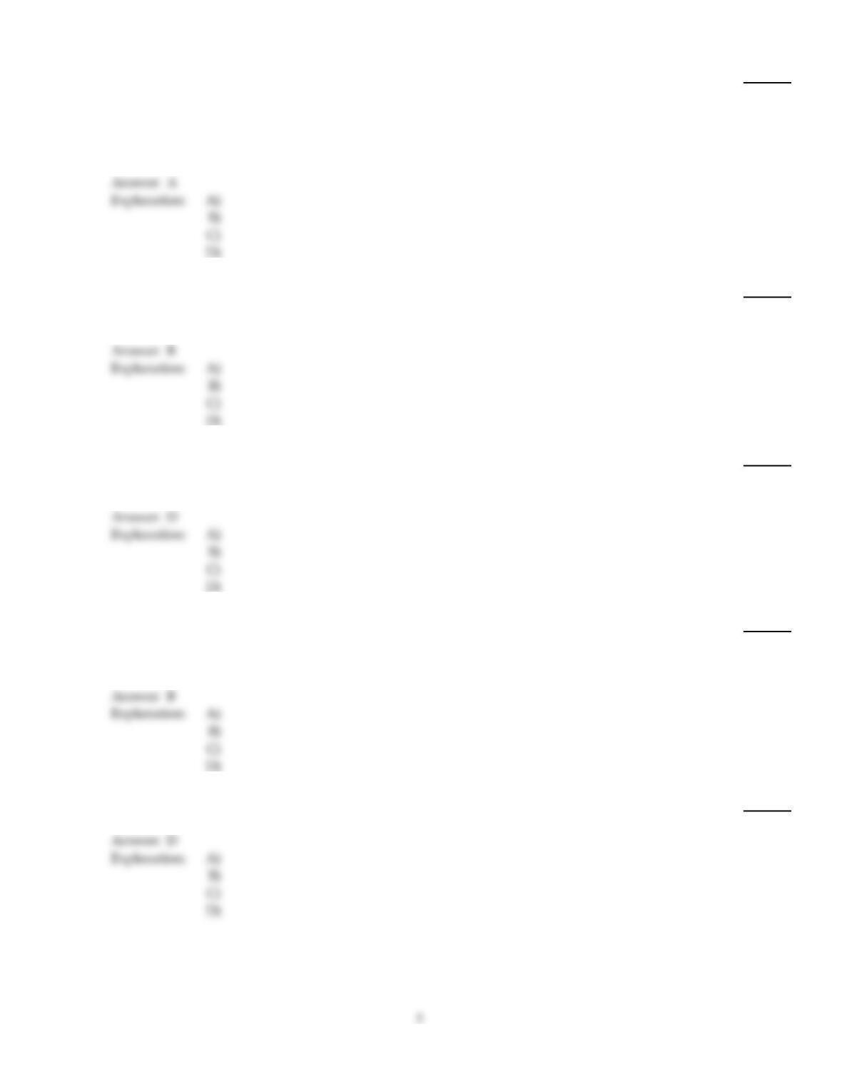
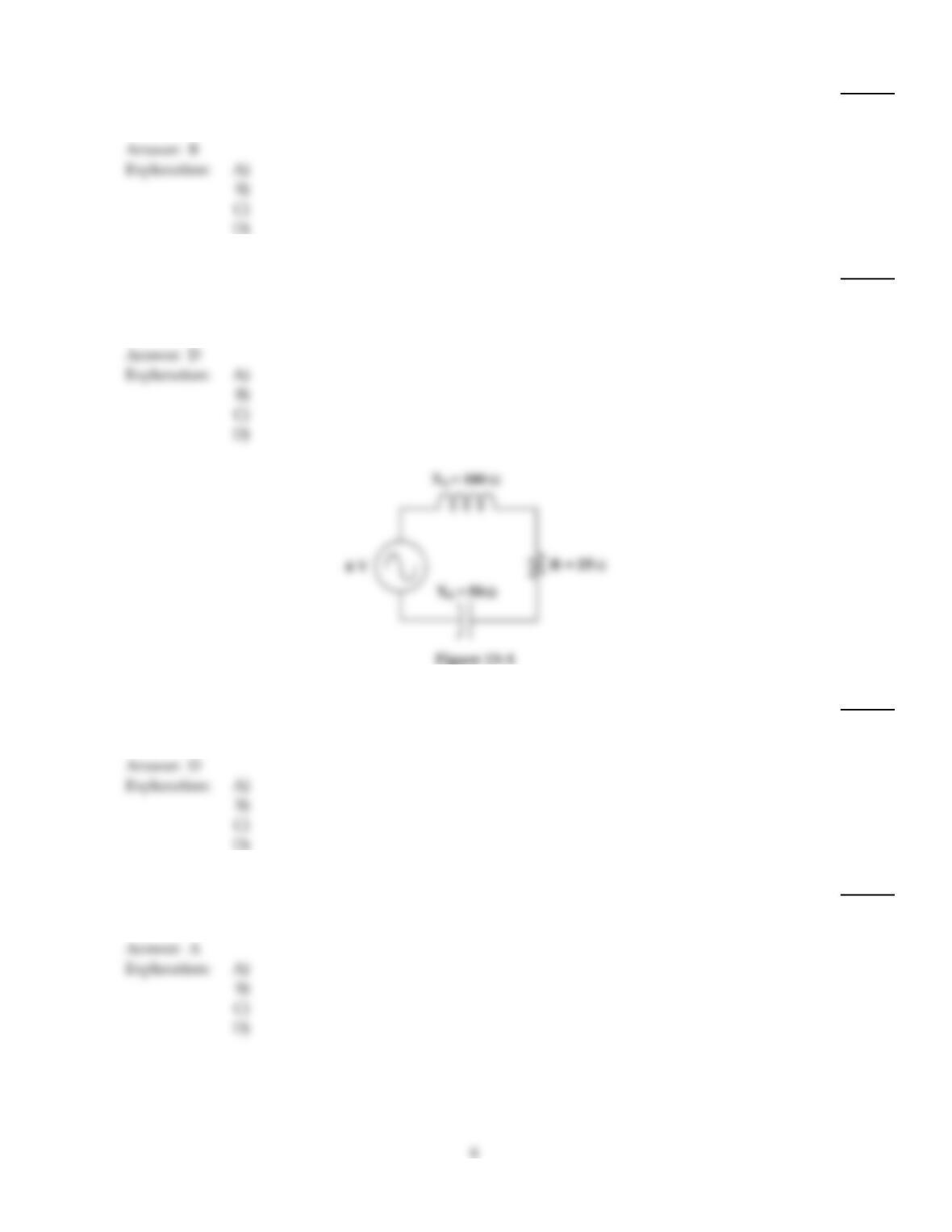
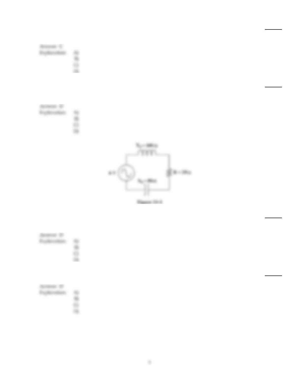
At resonance, the current in Figure 13–2 is ________.
4)
A)
10 A
B)
1.66 4
C)
10 mA
D)
1.66 mA
5)
If the resistor shorts in Figure 13–2, the current ________.
5)
A)
does not change
B)
decreases
C)
increases
D)
continues, but the circuit would not be resonant
6)
A resonant circuit with a high Q ________.
6)
A)
has no pass–band
B)
has a small voltage across the capacitor
C)
tunes sharply
D)
has a very wide pass–band
7)
In a series RLC circuit just above the resonant frequency, the impedance is:
7)
A)
more inductive.
B)
more capacitive.
C)
at minimum.
D)
at maximum.
8)
What is the source voltage in a series resonant circuit if VC= 150 V, VL= 150 V and VR= 50 V?
8)
A)
50 V
B)
350 V
C)
150 V
D)
300 V
9)
What is the resonant frequency of a tank circuit with a 50 mH inductor and C = 256 pF capacitor?
9)
A)
44.5 kHz
B)
4.45 kHz
C)
445 kHz
D)
44.5 Hz
10)
In a series RLC circuit just below the resonant frequency, the impedance is:
10)
A)
at maximum.
B)
at minimum.
C)
more inductive.
D)
more capacitive.
11)
The total reactance of a series RLC circuit at resonance is ________.
11)
A)
infinity
B)
equal to the resistance
C)
capacitive
D)
zero
12)
To operate the circuit in Figure 13–1 below the resonant frequency, ________ the resistance and
________ the frequency.
12)
A)
increase, increase
B)
do not change, increase
C)
do not change, decrease
D)
decrease, decrease
13)
Why does a resistive load increase the bandwidth of a given band–pass filter?
13)
A)
The resistance decreases the quality of the circuit.
B)
The resistance increases the quality of the circuit.
C)
A resistive load actually decreases the bandwidth.
D)
not enough information
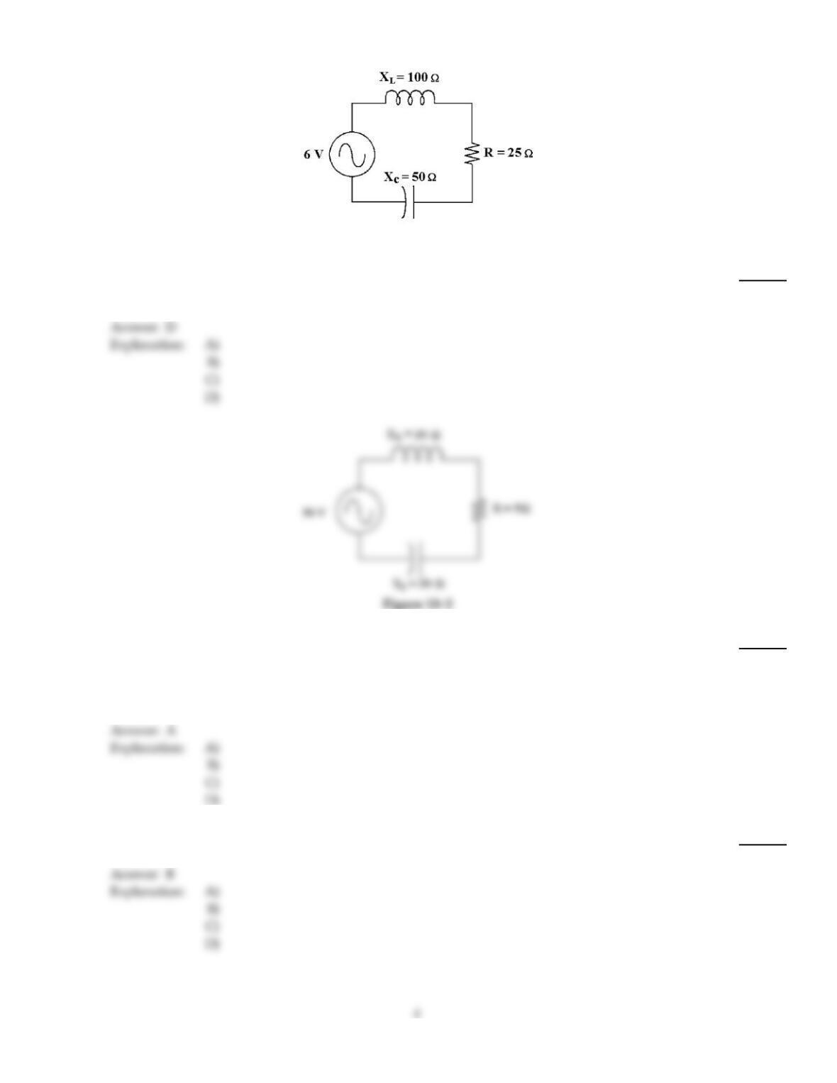
Figure 13–1
14)
If the resistance decreases in Figure 13–1, the impedance ________.
14)
A)
remains the same
B)
increases
C)
becomes zero
D)
decreases
15)
If the capacitor opens in Figure 13–2, the current ________.
15)
A)
decreases to zero
B)
increases because of the inductor
C)
continues to flow, but the circuit would not be resonant
D)
remains the same
16)
If a tuned tank circuit has a very wide bandwidth, its Q might be ________.
16)
A)
very high
B)
very low
C)
about 10
D)
about 100
17)
When tuning across the resonant frequency of a series RLC band–pass filter, which of the following
is true?
17)
A)
The impedance of the filter should be minimum at resonance.
B)
The output voltage across the load is minimum.
C)
The impedance of the filter should be maximum at resonance.
D)
Current flow through the load is minimum.
18)
What is the power at f1 and f2 in a resonant circuit that delivers 120 W?
18)
A)
17 W at both frequencies
B)
60 W
C)
84.8 W at f1 and 60 W at f2
D)
84.8 W
19)
In a series RLC circuit at resonance:
19)
A)
XC equals XL and they cancel.
B)
the impedance is mostly resistive.
C)
the impedance Z is at minimum.
D)
all of these.
20)
Replacing the inductor in a series resonant band–pass filter with one having a lower Q value causes
the bandwidth to ________.
20)
A)
be more selective
B)
increase
C)
remain the same
D)
decrease
21)
If an LC tank circuit is operating below resonance, the circuit is ________ in nature.
21)
A)
resistive
B)
positive
C)
capacitive
D)
inductive
22)
In a series RLC circuit at resonance, the capacitive reactance (XC) and the inductive reactance (XL):
22)
A)
are moderate.
B)
cancel each other.
C)
are minimum.
D)
add to each other.
23)
The selectivity of a given band–pass filter has degraded significantly, yet the fr is within tolerance.
Which of the following could have caused this?
23)
A)
The capacitance has increased.
B)
The inductance has increased.
C)
The load has opened.
D)
none of the above
24)
As the frequency approaches the resonant frequency in Figure 13–1, the VR ________.
24)
A)
remains the same
B)
becomes increasingly unstable
C)
decreases
D)
increases
25)
What is the total current in a parallel resonant circuit if its impedance is 0.22 M, the Q is 100 and
the source voltage is 100 V?
25)
A)
0.455 mA
B)
4.55 mA
C)
45.5 mA
D)
0.0455 mA
26)
What is the resonant impedance of a series RLC circuit with a 15 mH inductor, 0.015 µF capacitor
and 80 resistor?
26)
A)
30
B)
15 k
C)
80
D)
0
27)
What is the power at f1 and f2 in a resonant circuit that delivers 750 W?
27)
A)
375 W at f1 and 750 W at f2
B)
17 W at both frequencies
C)
750 W at both frequencies
D)
375 W at both frequencies
28)
If the frequency decreases in Figure 13–1, the impedance ________ and the phase angle ________.
28)
A)
increases, decreases
B)
decreases, increases
C)
increases, increases
D)
decreases, decreases
29)
Find the voltage across the capacitor in Figure 13–1.
29)
A)
–4.9 V
B)
10.7 V
C)
0.633 V
D)
5.37 V
30)
Which statement best describes the phase angle of a parallel RLC circuit at resonance?
30)
A)
Total current flow is minimum.
B)
With a net reactance at minimum the phase angle is zero.
C)
With a net reactance at maximum the phase angle is zero.
D)
either A or C
31)
What is the VOUT/VIN ratio (expressed in dB) of an RLC series resonant circuit with the output
across the inductor if the resonant frequency is 14 MHz, the source voltage is 12 V and the inductor
drops 300 V?
31)
A)
27.96 dB
B)
25 dB
C)
13.98 dB
D)
42.91 dB
32)
For the tuning circuit of a radio frequency receiver, the filter:
32)
A)
high Q components are not necessary.
B)
need not be highly selective.
C)
bandwidth should be narrow.
D)
any of the above
33)
What is the bandwidth of a resonant circuit if its resonant frequency is 14.2 MHz, the inductive
reactance is 3.5 k and the coil’s resistance is 8 ohm?
33)
A)
32.5 kHz
B)
14.2 MHz
C)
28.4 kHz
D)
2285 Hz
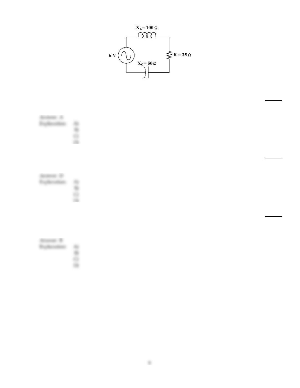
Figure 13–1
34)
If the resistance increases in Figure 13–1, the impedance ________.
34)
A)
increases
B)
remains the same
C)
becomes zero
D)
decreases
35)
If the resonant frequency is 1 MHz and Q = 50, f1= ________ and f2= ________.
35)
A)
0.98 MHz, 1.01 MHz
B)
0.99 MHz, 1.02 MHz
C)
0.98 MHz, 1.02 MHz
D)
0.99 MHz, 1.01 MHz
36)
What is the ratio of VOUT/VIN (expressed in dB) in an RLC series resonant circuit if the output
voltage is taken across the inductor, the resonant frequency is 14 MHz, the source voltage is 18 V
and the inductor drops 300 V?
36)
A)
28 dB
B)
24.4 dB
C)
14.0 dB
D)
42.9 dB
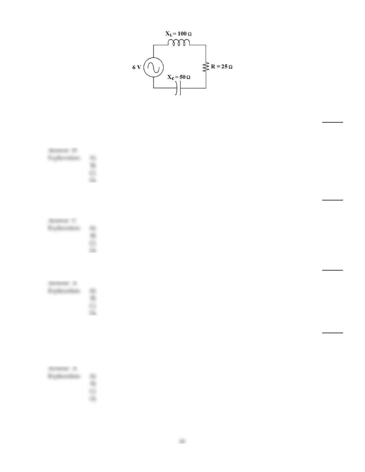
Figure 13–1
37)
If the frequency decreases in Figure 13–1, the impedance initally ________ and the current initially
________.
37)
A)
increases, increases
B)
decreases, decreases
C)
increases, decreases
D)
decreases, increases
38)
What is the bandwidth of the resonant circuit if the resonant frequency is 1.42 MHz, the inductive
reactance is 3.5 k and the coil’s resistance is 8 ohm?
38)
A)
32.5 kHz
B)
2285 Hz
C)
3.25 kHz
D)
1.42 MHz
39)
What is the resonant frequency of a tank circuit with a 150 mH inductor and a 300 pF capacitor?
39)
A)
23.7 kHz
B)
2.37 MHz
C)
237 kHz
D)
23.7 Hz
40)
Between the lower and upper critical frequencies of a band–pass filter:
40)
A)
the frequencies pass at 70% to their maximum levels.
B)
the frequencies pass a maximum level.
C)
the frequencies pass a minimum level.
D)
the frequencies pass at 30% to their maximum levels.
41)
If a tank circuit is operating above resonance, it is ________ in nature.
41)
A)
resistive
B)
capacitive
C)
positive
D)
inductive
42)
If frequency increases in Figure 13–1, the impedance ________ and the current ________.
42)
A)
increases, decreases
B)
decreases, decreases
C)
increases, increases
D)
decreases, increases
43)
In a parallel RLC circuit,at resonance the capacitive reactance (XC) and the inductive reactance
(XL):
43)
A)
equal and oppose current flow.
B)
add to each to cancel current flow.
C)
are minimum.
D)
are moderate.
44)
In an ideal parallel resonant circuit, the total current into the L and C branches is ________.
44)
A)
zero
B)
maximum
C)
high
D)
low
45)
If a tuned tank circuit has a very narrow bandwidth, its Q is probably ________.
45)
A)
very low
B)
about 10
C)
very high
D)
below 10
46)
In a parallel RLC circuit just above the resonant frequency, the impedance is:
46)
A)
at maximum.
B)
at minimum.
C)
more capacitive.
D)
more inductive.
47)
To operate the circuit in Figure 13–1 at resonance, ________ the resistance and ________ the
frequency.
47)
A)
don’t change, decrease
B)
don’t change, increase
C)
increase, increase
D)
decrease, decrease
48)
What is the lower cut off frequency in an RLC resonant circuit if the inductive reactance is 1.2 k,
the resonant frequency is 22 kHz and the resistance is 60 ?
48)
A)
21.5 kHz
B)
21.7 kHz
C)
21.8 kHz
D)
20.9 kHz
49)
If a resonant circuit has a low Q, it ________.
49)
A)
has a wide pass–band
B)
tunes sharply
C)
has a narrow pass–band
D)
has a small voltage across the capacitor
50)
If the resistance increases in Figure 13–2, the bandwidth ________.
50)
A)
remains the same
B)
varies
C)
decreases
D)
increases
51)
In a parallel RLC just below the resonant frequency, the impedance is:
51)
A)
more inductive.
B)
at maximum.
C)
at minimum.
D)
more capacitive.
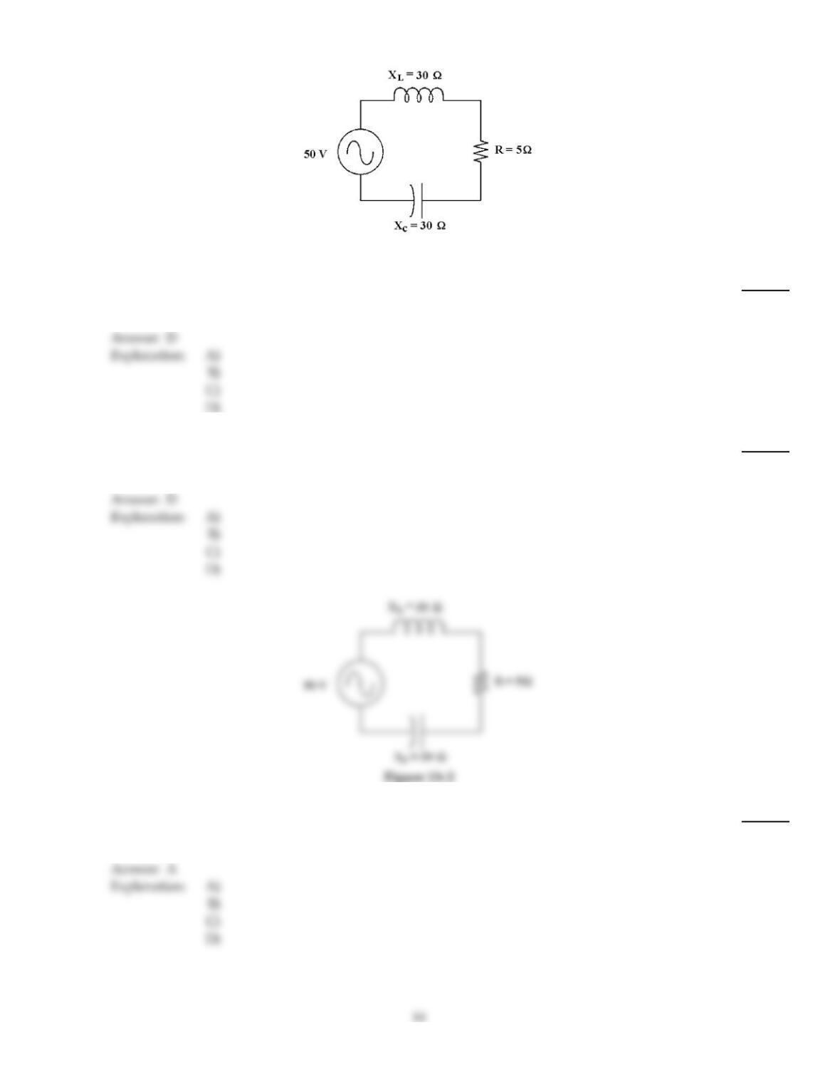
Figure 13–2
52)
If the current is 0 A in Figure 13–2, maybe ________.
52)
A)
the inductor is shorted
B)
the resistor has changed values to 100
C)
the capacitor is shorted
D)
the resistor is open
53)
In a parallel resonant RLC circuit, the impedance is ________ and the total current is ________.
53)
A)
minimum, maximum
B)
minimum, minimum
C)
maximum. maximum
D)
maximum, minimum
Figure 13–2
54)
If the resistance decreases in Figure 13–2, the bandwidth ________.
54)
A)
decreases
B)
varies
C)
remains the same
D)
increases
TRUE/FALSE. Write ‘T’ if the statement is true and ‘F’ if the statement is false.
55)
At resonance, a parallel RLC circuit is inductive.
55)
56)
At resonance, a parallel RLC circuit is capacitive.
56)
57)
A series RLC circuit can be configured for band–pass or band–stop filtering purposes.
57)
58)
At resonance, a series RLC circuit has maximum current.
58)
59)
The true power of an RLC circuit depends on the value of resistance.
59)
60)
In a resonant circuit, as Q increases the bandwidth decreases.
60)
61)
In a series resonant circuit, the impedance is minimum and the current is maximum.
61)
62)
At resonance, XC equals XL.
62)
63)
In a parallel resonant circuit, the impedance is minimum and the line current is maximum.
63)
64)
A resonant RLC circuit is said to be very selective if its Q is very low.
64)
65)
Current leads in a series RLC circuit with more capacitive reactance than inductive reactance.
65)
66)
The capacitor’s resistive effects are significant when considering the Q of an RLC circuit.
66)
67)
At resonance, the impedance of a series RLC circuit equals its resistance.
67)
68)
A highly selective filter has a very wide bandwidth.
68)
69)
The total impedance equals the resistance of a resonant series RLC circuit.
69)
Answer Key
Testname: C13
Answer Key
Testname: C13
18