Exam
Name___________________________________
MULTIPLE CHOICE. Choose the one alternative that best completes the statement or answers the question.
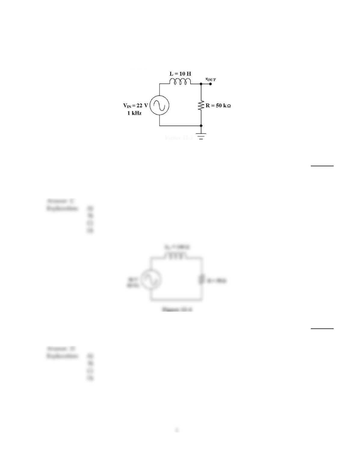
Figure 12–3
1)
If some of the turns of the inductor in Figure 12–3 have shorted, how will the circuit change?
1)
A)
The output voltage at the cutoff frequency will decrease.
B)
The cutoff frequency will decrease.
C)
The cutoff frequency will increase.
D)
The output voltage at the cutoff frequency will increase.
2)
If the operating frequency decreases in Figure 12–1, the current ________.
2)
A)
decreases
B)
remains the same
C)
decreases to zero
D)
increases
3)
What is the voltage across the inductor in Figure 12–1?
3)
A)
0.894 V
B)
4.47 V
C)
0.4 V
D)
44.6 V
4)
In an RL filter circuit, the cutoff frequency is defined as the frequency at which:
4)
A)
the output voltage drops to 66% of maximum.
B)
the output voltage drops to 70% of maximum.
C)
the output voltage is cutoff, with minimum or zero output.
D)
the output voltage drops to 33% of maximum.
5)
Calculate the true power in Figure 12–1.
5)
A)
10 W
B)
4 W
C)
1 W
D)
400 mW
6)
If a low–pass RL filter’s cutoff frequency is 20 kHz, its bandwidth is ________.
6)
A)
40 kHz
B)
0 Hz
C)
20 kHz
D)
unknown
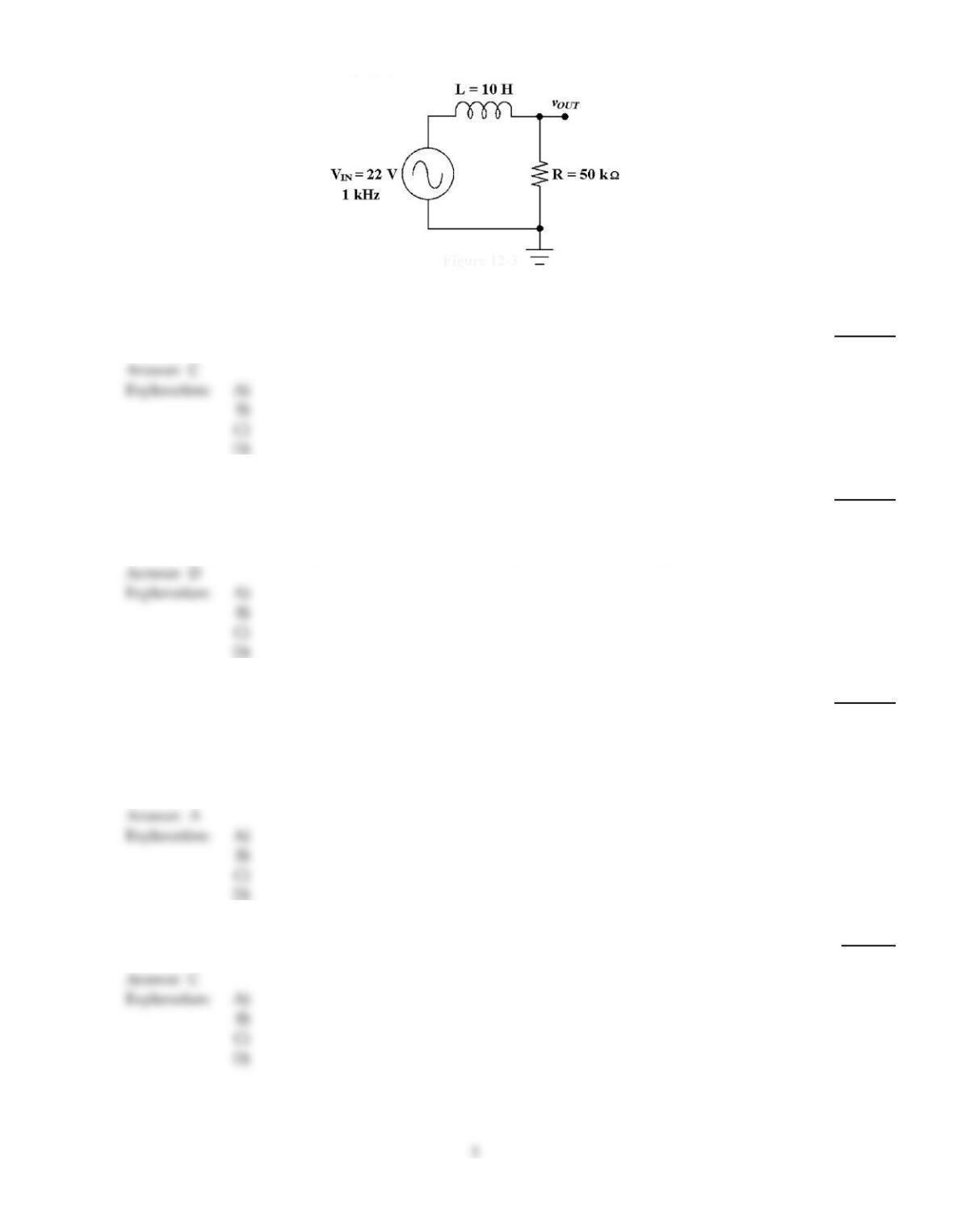
Figure 12–3
7)
What is the phase angle in Figure 12–3, at the cutoff frequency?
7)
A)
49.9°
B)
54.3°
C)
45.0°
D)
51.4°
8)
In a series RL circuit, as the phase angle between the applied voltage and the total current
increases, this is the same as:
8)
A)
apparent power decreasing.
B)
true power decreasing.
C)
power factor increasing.
D)
power factor decreasing.
9)
It is suspected that a high pass filter’s cutoff frequency has changed. What pieces of test equipment
could be used to check it out?
9)
A)
voltmeter and a sine wave generator
B)
an oscilloscope and a square wave generator
C)
either A or B
D)
none of the above
10)
If a load is purely inductive and the reactive power is 10 VAR, the apparent power is ________.
10)
A)
1.144 VA
B)
14.14 VA
C)
10 VA
D)
3.16 VA
11)
If a high–pass RL filter‘s cutoff frequency is 55 kHz, its bandwidth is theoretically ________.
11)
A)
0 kHz
B)
110 kHz
C)
55 kHz
D)
infinite
12)
A measured voltage of 0 V across the resistor in a parallel RL circuit would indicate:
12)
A)
a blown fuse.
B)
an open in the resistor.
C)
an short in the inductor.
D)
either A or B.
13)
The circuit in Figure 12–3 is known as a ________ filter.
13)
A)
low–pass
B)
band–pass
C)
notch
D)
high–pass
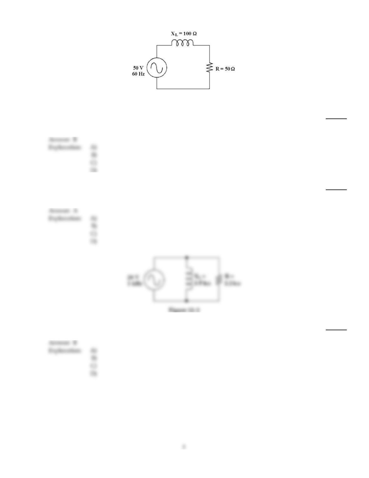
Figure 12–1
14)
If the operating frequency decreases in Figure 12–1, the inductance ________.
14)
A)
decreases to zero
B)
remains the same
C)
decreases
D)
increases
15)
If the operating frequency decreases in Figure 12–1, the phase angle ________.
15)
A)
decreases
B)
remains the same
C)
changes to another quadrant
D)
increases
16)
If the resistance increased to 10 k in Figure 12–2, the total impedance is ________.
16)
A)
13.2 k
B)
3.30 k
C)
6.61 k
D)
infinite
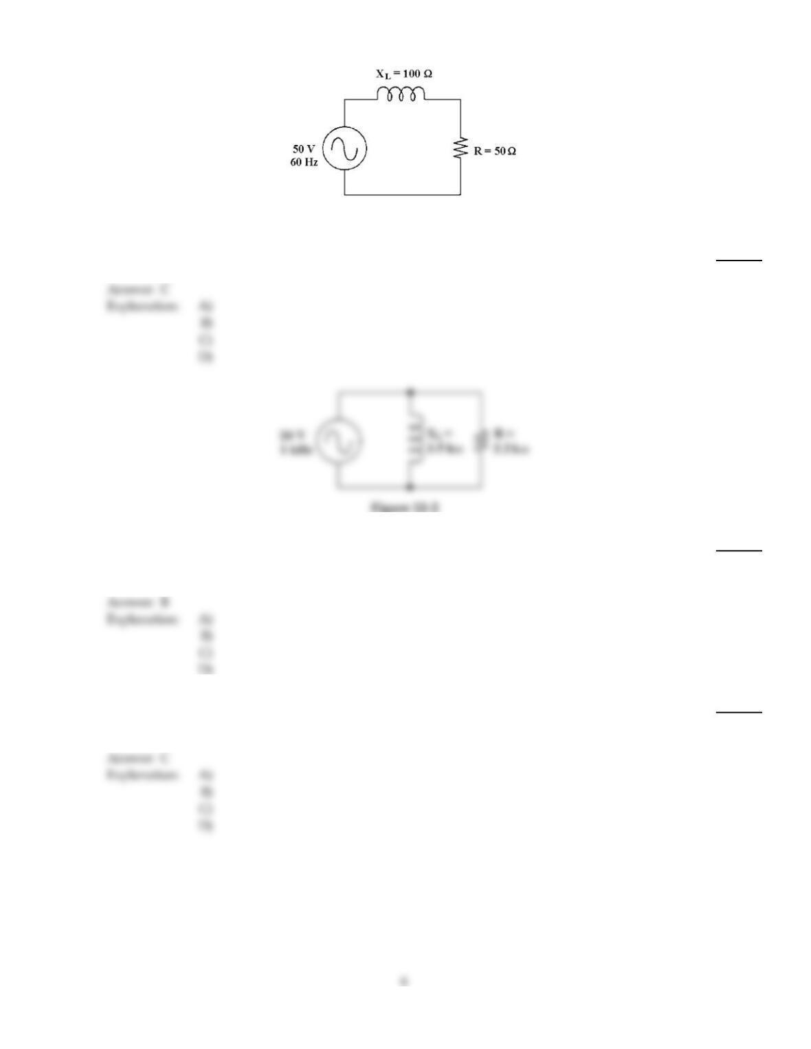
Figure 12–1
17)
If the frequency is 60 Hz in Figure 12–1, what is the inductance?
17)
A)
3.77 mH
B)
26.5 mH
C)
265 mH
D)
3.77 H
18)
Which statement describes the relationship of IL and IR in Figure 12–2?
18)
A)
They are 180° out of phase.
B)
IL lags IR.
C)
They are in phase.
D)
IL leads IR.
19)
What change would decrease the power factor in Figure 12–2?
19)
A)
Decrease the value of the resistor.
B)
Increase the source voltage.
C)
Increase the value of the resistor.
D)
Decrease the source voltage.
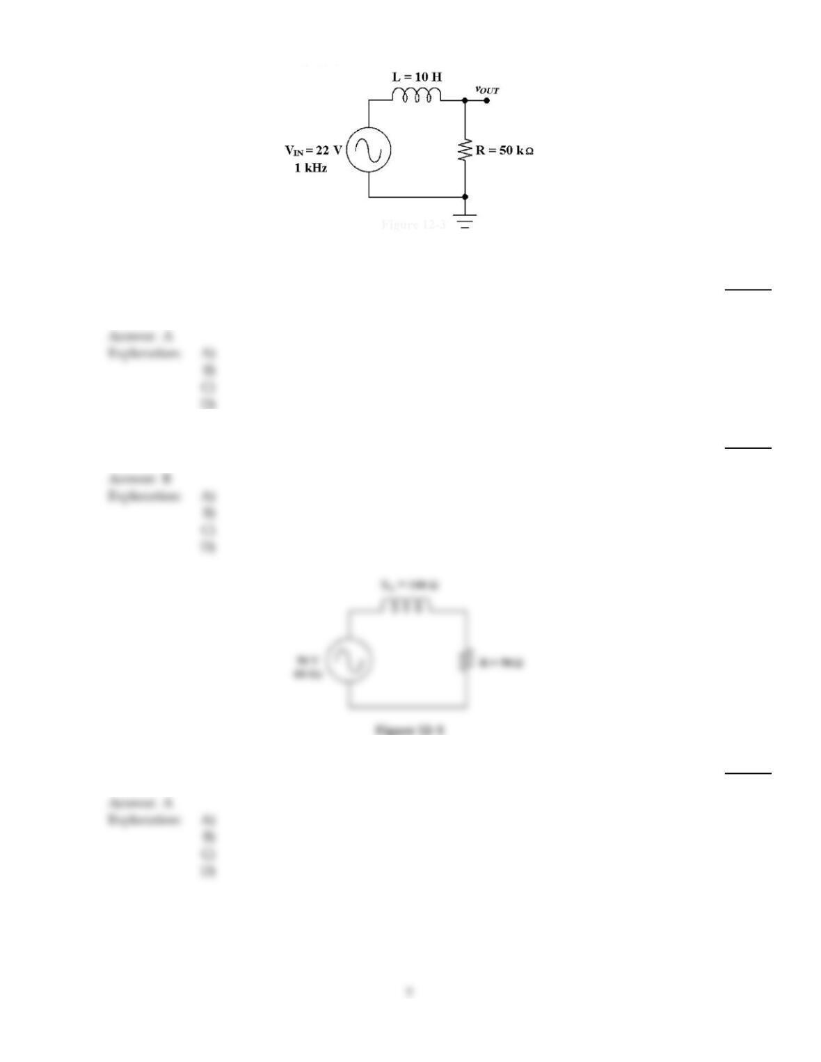
Figure 12–3
20)
If the output is taken across the inductor in Figure 12–3, the circuit is known as a ________.
20)
A)
high–pass filter
B)
band–pass filter
C)
low–pass filter
D)
notch filter
21)
What is VOUT at the cutoff frequency in Figure 12–3?
21)
A)
15.1 V
B)
15.6 V
C)
14.4 V
D)
12.9 V
Explanation:
22)
If the frequency is 400 Hz in Figure 12–1, what is the inductance?
22)
A)
39.8 mH
B)
25.12 H
C)
39.8 H
D)
25.1 mH
Explanation:
Explanation:
23)
If the resistive current is 2 A and the inductive current is 2 A in a parallel RL circuit, total current is
________.
23)
A)
2 A
B)
2.83 A
C)
5.66 A
D)
4 A
24)
After having troubleshot a series RL circuit, you check the resistance of the inductor and it is
around 40 ohms. What conclusion does this bring you to?
24)
A)
Since the inductor’s voltage was nearly zero, the inductor is probably okay, so the resistor
must be open.
B)
Since the inductor’s voltage was nearly zero, you are sure the windings have shorted.
C)
Since the inductor’s voltage was nearly zero, the inductor is probably okay so the resistor
must be shorted.
D)
not enough information
25)
If the resistor decreases in Figure 12–2, the total current ________.
25)
A)
remains the same
B)
decreases
C)
increases
D)
decreases to zero
26)
In a RL circuit, the inductive reactance is:
26)
A)
directly proportional to the frequency.
B)
increases as the frequency increases.
C)
directly proportional to the inductance.
D)
all of these.
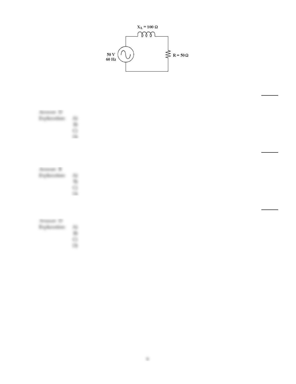
Figure 12–1
27)
If the frequency decreases in Figure 12–1, the phase angle ________ and the current ________.
27)
A)
increases, decreases
B)
increases, increases
C)
decreases, decreases
D)
decreases, increases
28)
If the frequency increases in Figure 12–1, the phase angle ________ and the impedance ________.
28)
A)
decreases, increases
B)
increases, increases
C)
decreases, decreases
D)
increases, decreases
29)
If VR is 10 V and VL is 10 V in a series RL circuit, the source voltage equals ________.
29)
A)
20 V
B)
10 V
C)
28.3 V
D)
14.1 V
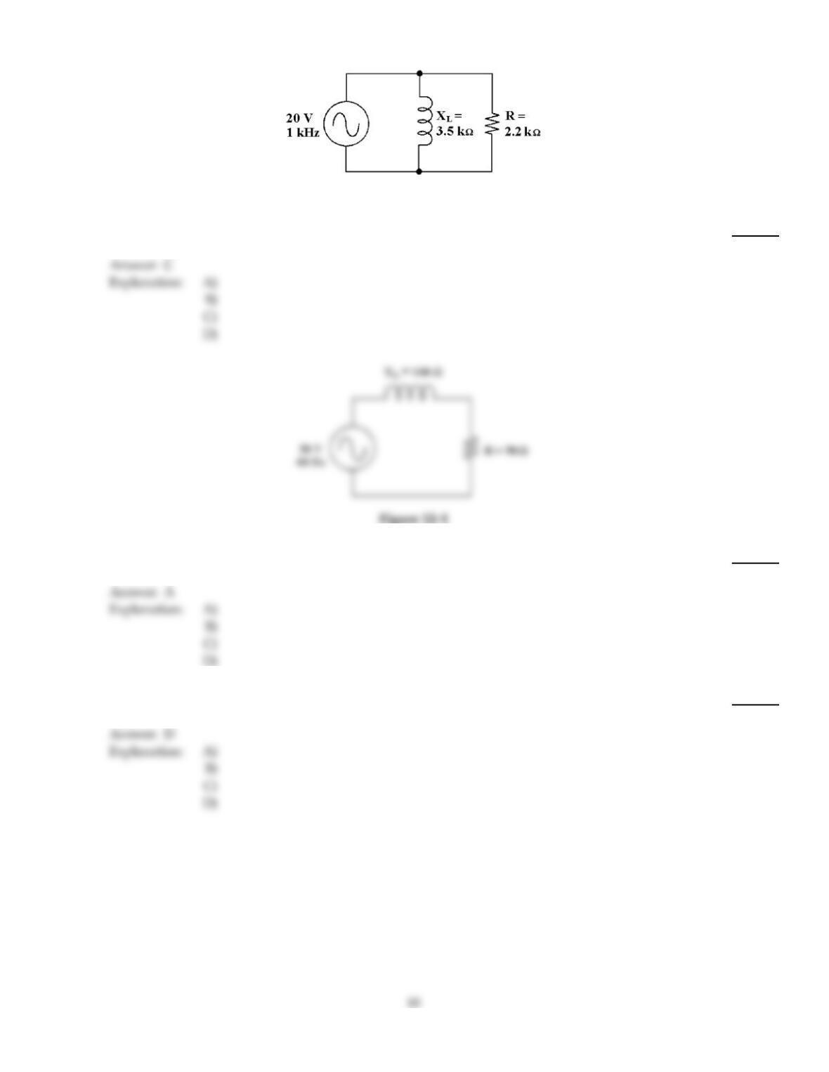
Figure 12–2
30)
What is the total impedance in Figure 12–2?
30)
A)
5.71 k
B)
9.09 k
C)
1.86 k
D)
1.07 k
31)
What is the impedance in Figure 12–1?
31)
A)
112
B)
104
C)
1120
D)
1040
32)
If the source voltage changes to 100 V in Figure 12–1, the true power is ________.
32)
A)
16 W
B)
4 W
C)
40 mW
D)
40 W
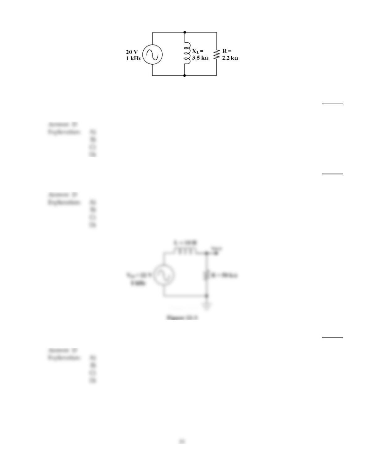
Figure 12–2
33)
If the resistance increases in Figure 12–2, the total current ________.
33)
A)
decreases to zero
B)
remains the same
C)
increases
D)
decreases
34)
When an ac voltage is supplied to an RL circuit, the ac’s current and amplitude will be:
34)
A)
varying in the same manner.
B)
lagging the voltage.
C)
similar in waveform.
D)
all of these.
35)
What is the cutoff frequency in Figure 12–3?
35)
A)
7.96 kHz
B)
637 kHz
C)
637 Hz
D)
796 Hz
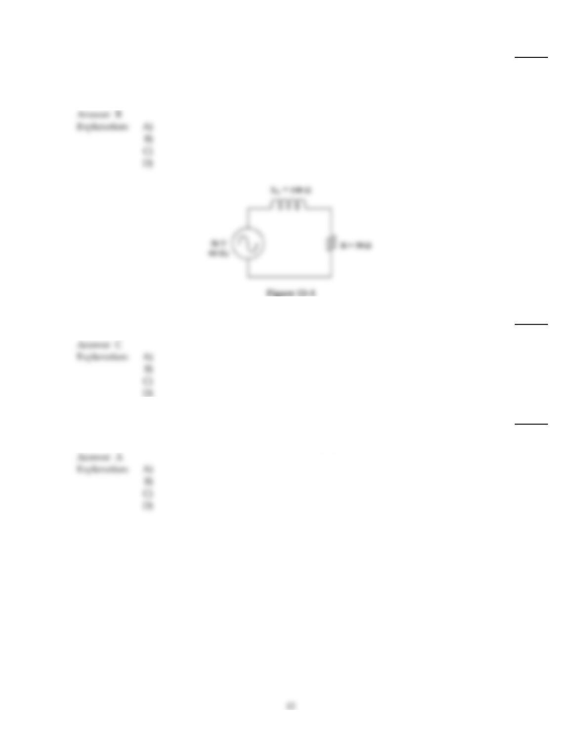
36)
What effect will an open inductor have on the circuit in Figure 12–3?
36)
A)
The output voltage at the cutoff frequency will decrease.
B)
The current will drop to zero.
C)
The output voltage at the cutoff frequency will increase.
D)
The cutoff frequency will increase.
37)
What is the apparent power in Figure 12–1?
37)
A)
0.4 VA
B)
0.8 VA
C)
22.27 VA
D)
8.94 VA
C
Explanation:
38)
An RL lag network is similar to a:
38)
A)
low pass filter.
B)
band pass filter.
C)
stop pass filter.
D)
high pass filter.
A
Explanation:
B
Explanation:
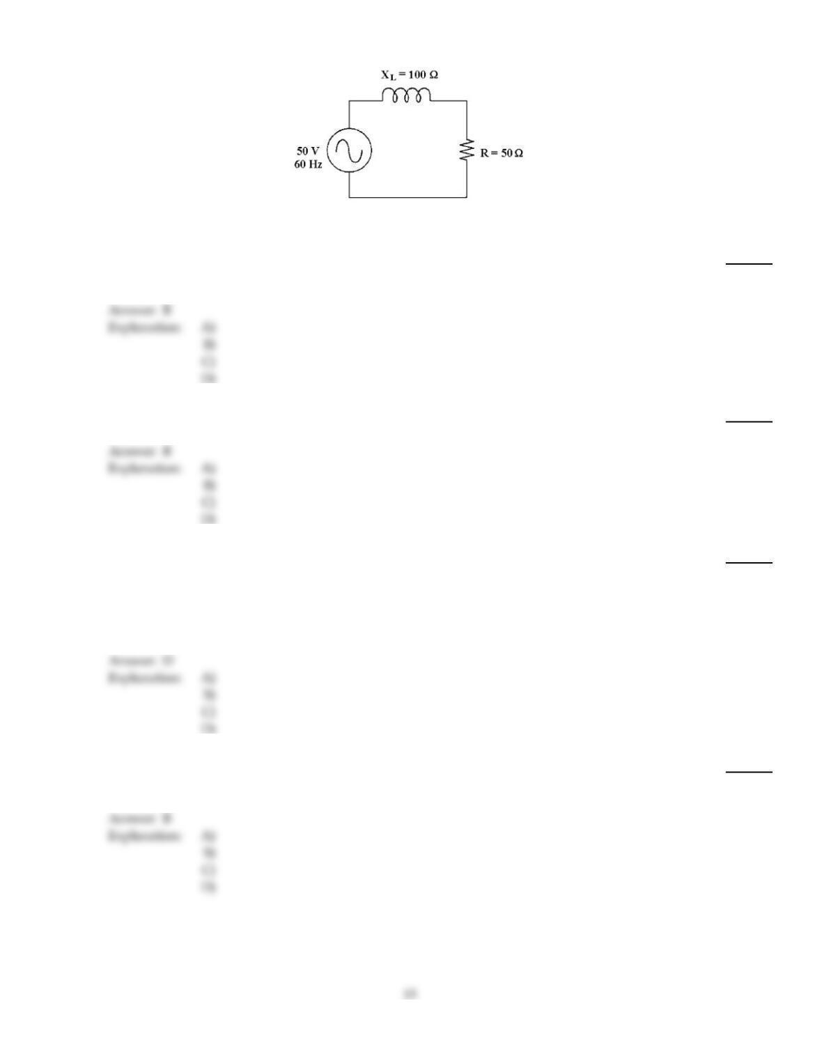
Figure 12–1
39)
If the frequency increases in Figure 12–1, the phase angle ________.
39)
A)
remains the same
B)
increases
C)
decreases
D)
changes to another quadrant
40)
What is the cutoff frequency in Figure 12–1?
40)
A)
408 Hz
B)
63 Hz
C)
25 Hz
D)
30 Hz
41)
The voltage measured across the inductor in a series RL has dropped significantly from normal.
What could possibly be the problem?
41)
A)
The resistor has gone up in value.
B)
partial shorting of the windings of the inductor
C)
The resistor has gone down in value.
D)
either A or B
42)
Which of the following is typically most important of the three types of power in terms of work
being done?
42)
A)
apparent
B)
true
C)
reactive
D)
inductive
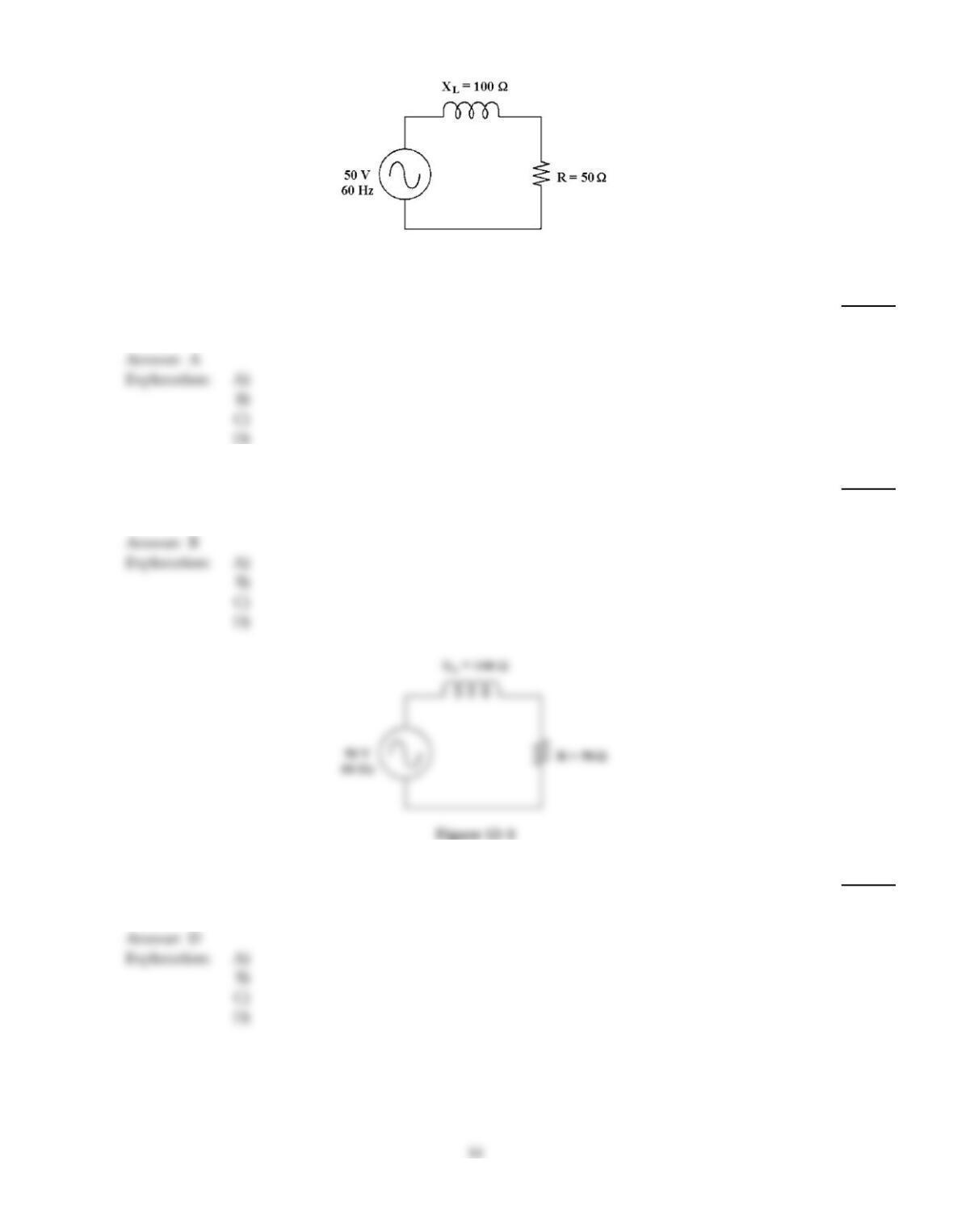
Figure 12–1
43)
If the frequency increases in Figure 12–1, the phase angle ________ and the current ________.
43)
A)
increases, decreases
B)
increases, increases
C)
decreases, increases
D)
decreases, decreases
44)
An RL high pass filter takes its output across:
44)
A)
the parallel resistor.
B)
the series inductor.
C)
the series resistor.
D)
the parallel inductor.
Figure 12–1
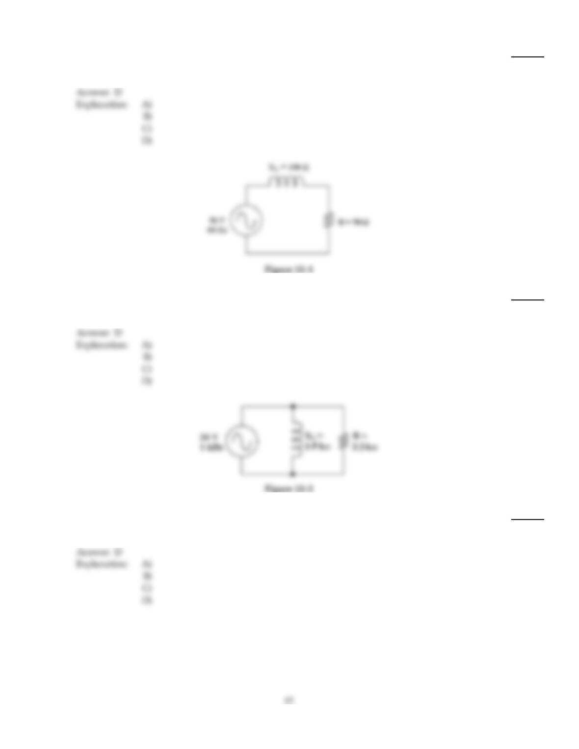
45)
If the frequency decreases in Figure 12–1, the phase angle ________ and the impedance ________.
45)
A)
decreases, increases
B)
increases, increases
C)
increases, decreases
D)
decreases, decreases
46)
Power in an RL circuit can be measured as:
46)
A)
reactive power (Pr).
B)
true power (Ptrue).
C)
apparent power (Pa).
D)
all of these.
47)
If the frequency increases in Figure 12–1, the current ________.
47)
A)
increases
B)
remains the same
C)
decreases to zero
D)
decreases
48)
What change would increase the power factor in Figure 12–2?
48)
A)
increasing the value of the resistor
B)
decreasing the source voltage
C)
increasing the source voltage
D)
decreasing the value of the resistor
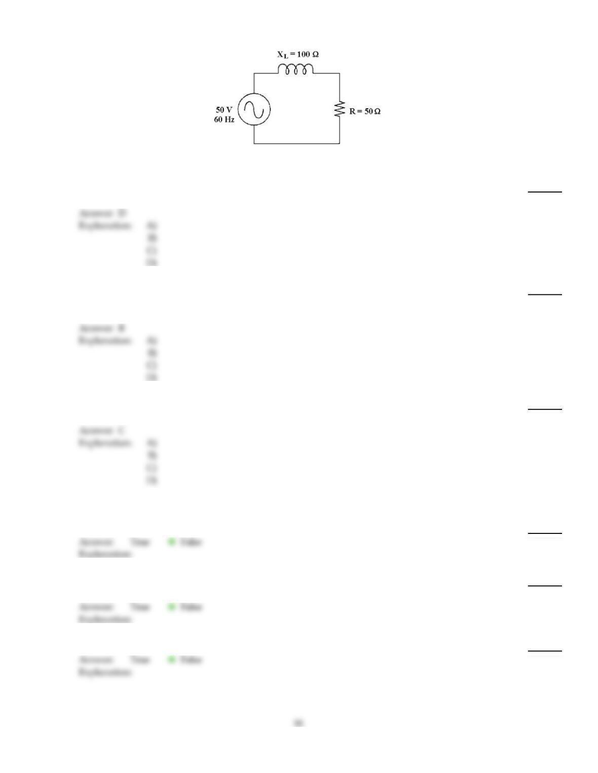
Figure 12–1
49)
What is the phase angle in Figure 12–1?
49)
A)
54.3°
B)
86.3°
C)
71.2°
D)
63.4°
50)
If the frequency increases in Figure 12–1, inductance ________.
50)
A)
decreases
B)
remains the same
C)
decreases to zero
D)
increases
B
51)
If the true power is 10 W and the reactive power is 10 VAR, the apparent power is ________.
51)
A)
20 VA
B)
5 VAT
C)
14.1 VA
D)
100 VA
C
TRUE/FALSE. Write ‘T’ if the statement is true and ‘F’ if the statement is false.
52)
A low–pass filter passes high frequencies and blocks other frequencies.
52)
53)
The overall phase angle of a parallel circuit with a resistance of 20 and an inductive reactance of
25 k would be nearly 90 degrees.
53)
54)
The output at the cutoff frequency of a low pass RL filter is 0 V.
54)
D
55)
An ohmmeter can be used to accurately test the impedance of an RL circuit.
55)
56)
The source voltage always lags the total current in an RL circuit.
56)
57)
The impedance of a series RL circuit is found by directly adding the values of XL and R.
57)
58)
If the inductance increases in an RL filter circuit, the cutoff frequency increases.
58)
59)
If the resistance decreases in an RL filter circuit, the cutoff frequency increases.
59)
60)
The source voltage always leads the total current in an RL circuit.
60)
61)
Power dissipated by the resistor in a parallel RL circuit can be increased with the addition of a
capacitor in parallel.
61)
62)
If the frequency increases in an RL circuit, the impedance decreases.
62)
63)
The impedance of a series RL circuit is found by adding the values of XL and R using a phasor
diagram.
63)
64)
A high–pass filter passes high frequencies and blocks low frequencies.
64)
65)
The impedance of an RL series circuit varies inversely with the frequency.
65)

Answer Key
Testname: C12

Answer Key
Testname: C12
19