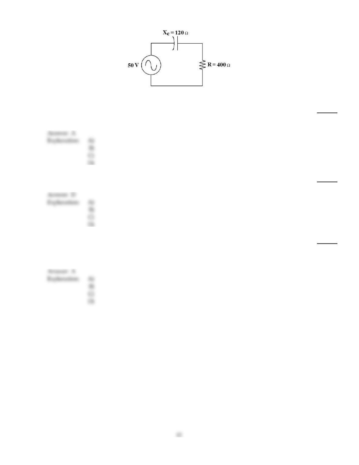
Figure 10–1
34)
If the operating frequency increases in Figure 10–1, how does the phase angle change?
34)
A)
It decreases.
B)
It remains the name.
C)
It changes to another quadrant.
D)
It increases.
35)
Calculate the apparent power in Figure 10–1.
35)
A)
14.37 VA
B)
1.70 VA
C)
5.66 VA
D)
5.99 VA
36)
The output voltage of an RC high pass filter at a designated frequency is low. What is a possible
problem?
36)
A)
function generator misadjusted
B)
open resistor
C)
shorted capacitor
D)
not enough information
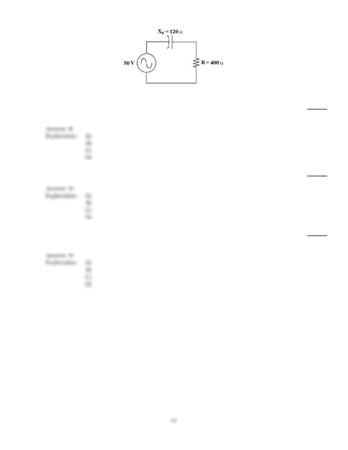
Figure 10–1
37)
If the operating frequency decreases in Figure 10–1, how does the current change?
37)
A)
It remains the same.
B)
It decreases.
C)
It decreases to zero.
D)
It increases.
38)
If the bandwidth of a low–pass filter is 0 to 1 kHz, the cutoff frequency is ________.
38)
A)
500 Hz
B)
2 kHz
C)
0 Hz
D)
1 kHz
39)
An RC high pass filter takes its output across:
39)
A)
the parallel capacitor.
B)
the parallel resistor.
C)
the series capacitor.
D)
the series resistor.
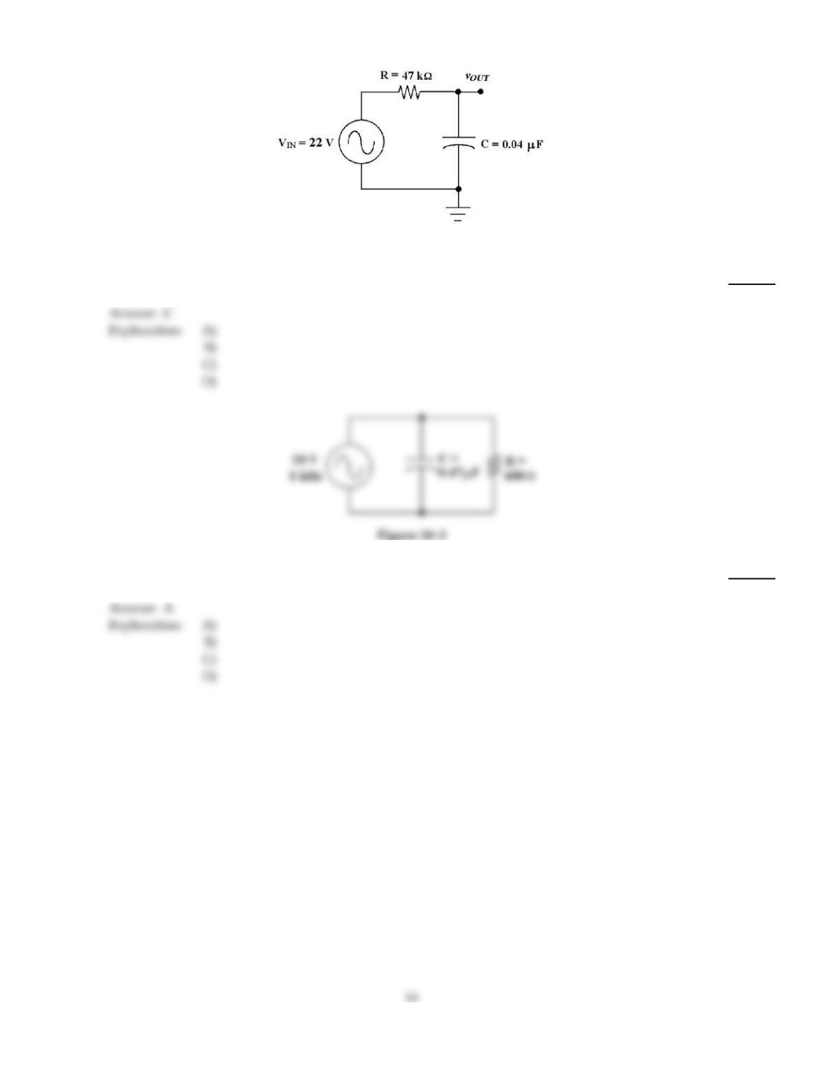
Figure 10–3
40)
If the resistor changes to 2.2 k in Figure 10–3, the new cutoff frequency equals ________.
40)
A)
1.18 kHz
B)
995 Hz
C)
1.81 kHz
D)
1.01 kHz
41)
Calculate the total impedance in Figure 10–2.
41)
A)
258
B)
1000
C)
62
D)
880
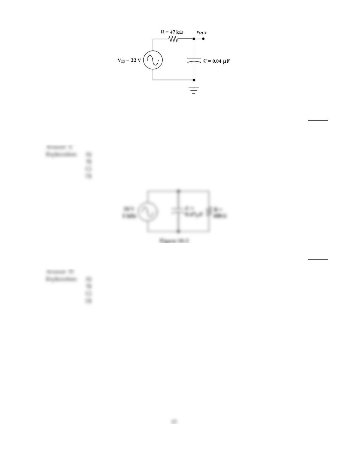
Figure 10–3
42)
If the output were taken across the resistor in Figure 10–3, the circuit would be known as a
________.
42)
A)
band–pass filter
B)
low–pass filter
C)
high–pass filter
D)
band–notch filter
43)
How much voltage does the capacitor drop in Figure 10–2?
43)
A)
59 mV
B)
19.94 V
C)
10 V
D)
20 V
Explanation:
Explanation:
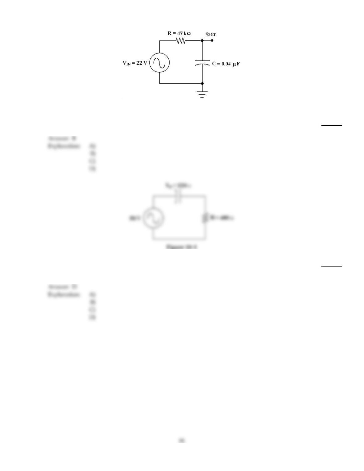
Figure 10–3
44)
If the resistor is changed to 100 k in Figure 10–3, what is the new cutoff frequency?
44)
A)
79.6 Hz
B)
39.8 Hz
C)
318 Hz
D)
159 Hz
45)
If the operating frequency increases in Figure 10–1, how does the resistor value change?
45)
A)
It decreases.
B)
It opens.
C)
It increases.
D)
It remains the same.
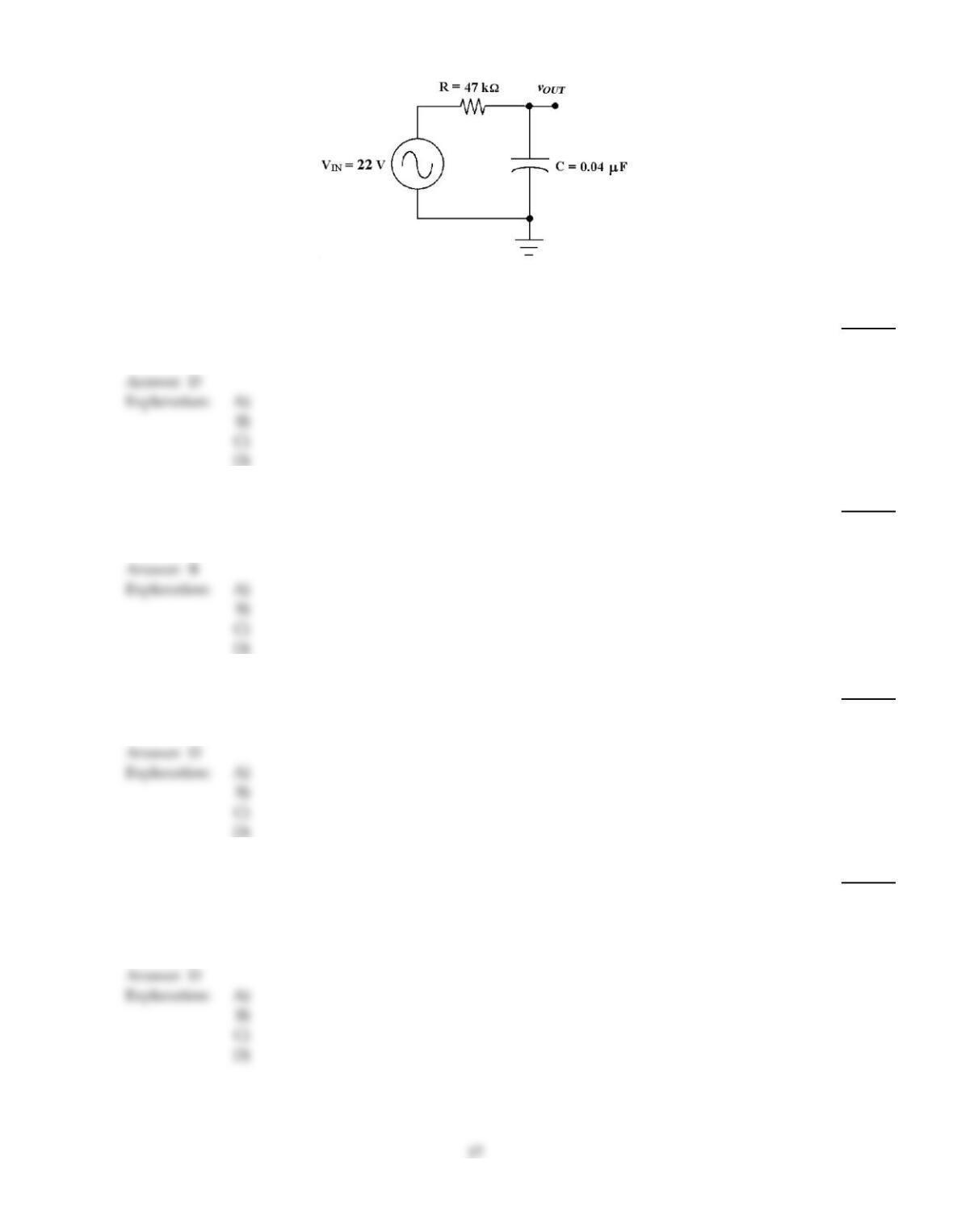
Figure 10–3
46)
What is the circuit fault in Figure 10–3 if the output voltage equals 0 V at the cutoff frequency?
46)
A)
The resistor has shorted.
B)
The capacitor has opened.
C)
The capacitor has become leaky.
D)
The capacitor has shorted.
47)
If there is 1 ARMS through the resistor and 1 ARMS through the capacitor in a parallel RC circuit,
then the total current equals ________.
47)
A)
1 ARMS
B)
1.41 ARMS
C)
2.28 ARMS
D)
2 ARMS
48)
In an RC circuit, the capacitive reactance is:
48)
A)
decreases as the frequency increases.
B)
inversely proportional to the frequency.
C)
inversely proportional to the capacitance.
D)
all of these.
49)
In an RC filter circuit, the cutoff frequency is defined as the frequency at which:
49)
A)
the output voltage is cutoff, with minimum or zero output.
B)
the output voltage drops to 66% of maximum.
C)
the output voltage drops to 33% of maximum.
D)
the output voltage drops to 70% of maximum.
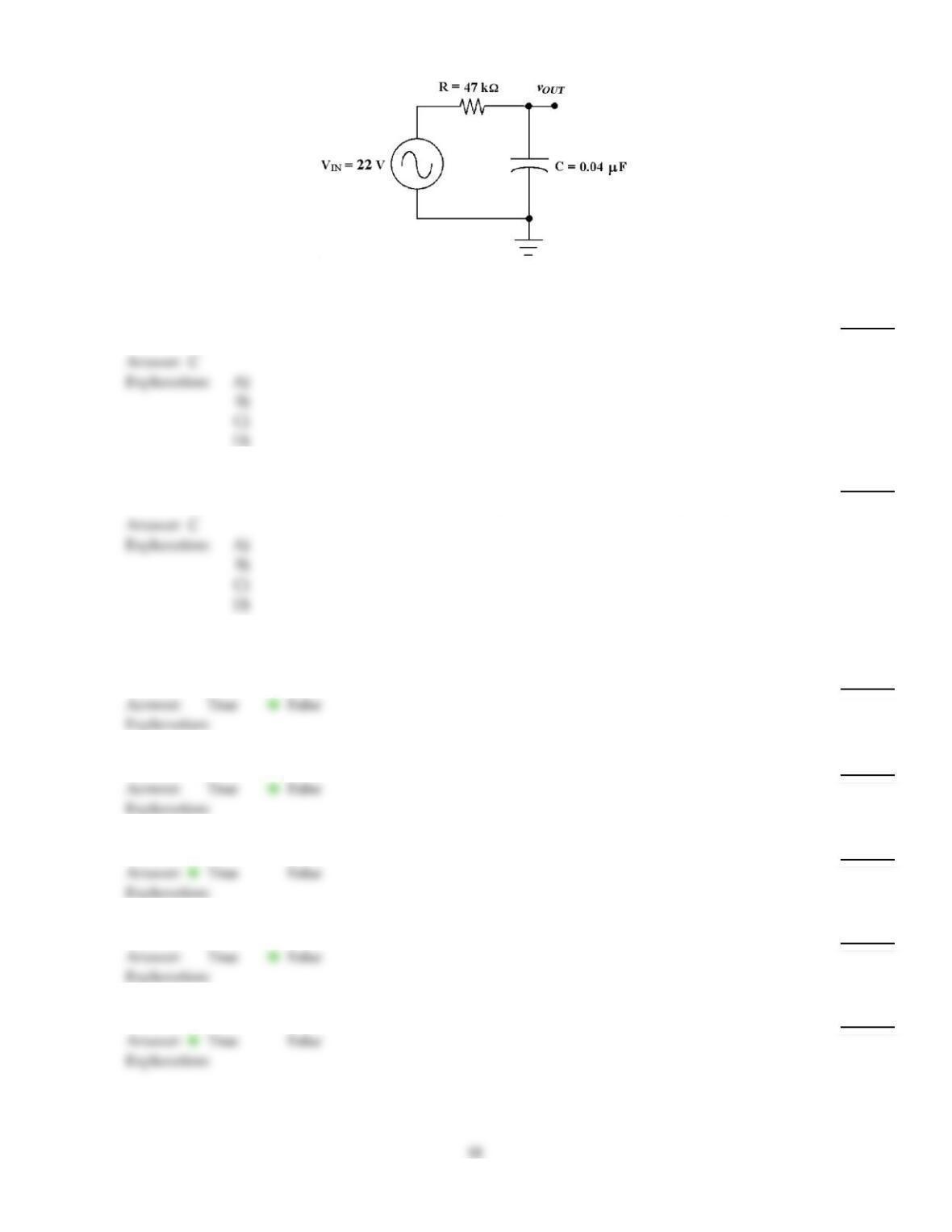
Figure 10–3
50)
What is the cutoff frequency in Figure 10–3?
50)
A)
1012 Hz
B)
118 Hz
C)
85 Hz
D)
995 Hz
51)
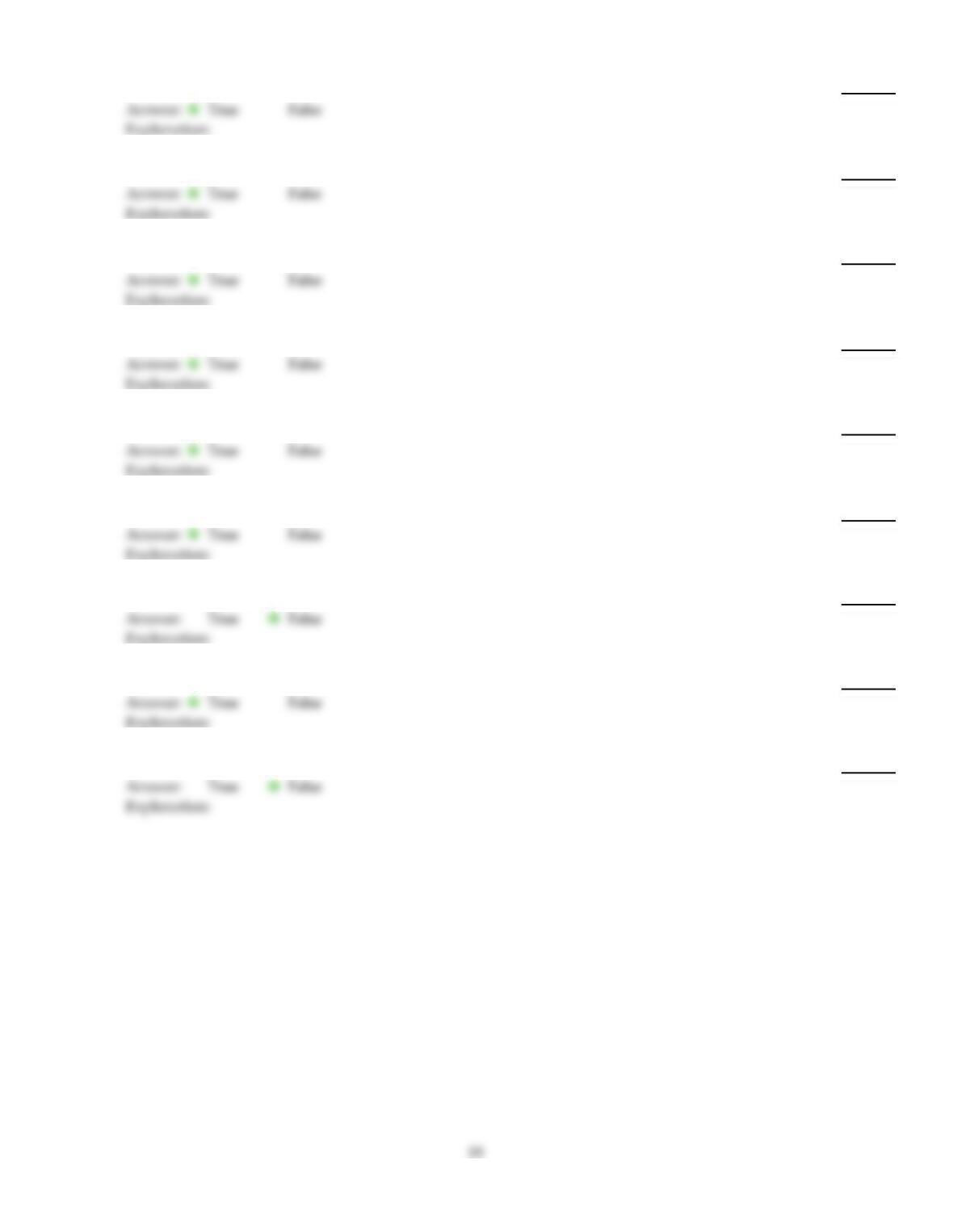
If the resistance is reduced to 4 k in Figure 10–3, the cutoff frequency equals ________.
51)
A)
99 Hz
B)
480 Hz
C)
995 Hz
D)
6250 Hz
TRUE/FALSE. Write ‘T’ if the statement is true and ‘F’ if the statement is false.
52)
As the frequency applied to an RC circuit varies, both XC and resistance vary.
52)
53)
A leaky capacitor can be equated as a capacitor with a resistor being placed in series with it.
53)
54)
The phase angle of an RC circuit varies inversely with frequency.
54)
55)
Power factor values close to 0 denotes an RC circuit with mostly true power.
55)
56)
As the frequency applied to an RC circuit increases, the impedance decreases.
56)
57)
The phasor combination of XC and R is called Z.
57)
58)
A VA rating is more relevant when judging the current delivery capacity for a given signal source.
58)
59)
The phasor combination of VR and VC in an RC series circuit equals the source voltage.
59)
60)
An RC circuit can be used as a filter to eliminate selected frequencies.
60)
61)
When the frequency applied to an RC circuit varies, the value of XC varies.
61)
62)
A high pass filter will cause some phase shifting of the signal.
62)
63)
As the frequency applied to an RC circuit is decreased, the phase angle decreases.
63)
64)
The total current in an RC circuit always leads the source voltage.
64)
65)
The total current in an RC circuit always lags the source voltage.
65)
Answer Key
Testname: C10
Answer Key
Testname: C10
21