Exam
Name___________________________________
MULTIPLE CHOICE. Choose the one alternative that best completes the statement or answers the question.
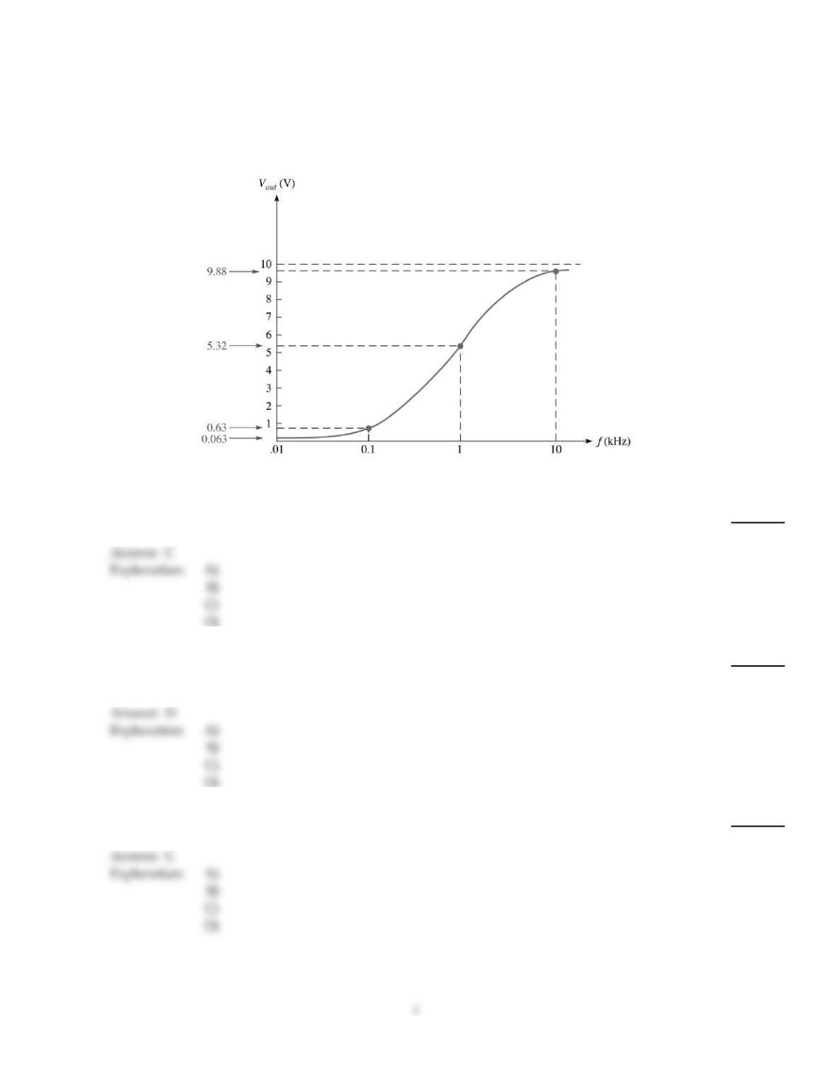
Figure 10–4
1)
This frequency response curve in Figure 10–4 represents what type of filter?
1)
A)
low pass
B)
band stop
C)
high pass
D)
band pass
2)
When an AC voltage is supplied to an RC circuit, the AC’s current and amplitude will be:
2)
A)
varying in the same manner.
B)
similar in waveform.
C)
leading the voltage.
D)
all of these.
3)
If the true power is 100 W and the reactive power is 100 VAR, the apparent power is ________.
3)
A)
200 VA
B)
141 W
C)
141 VA
D)
100 VA
4)
Power in an RC circuit can be measured as:
4)
A)
apparent power (Pa).
B)
true power (Ptrue).
C)
reactive power (Pr).
D)
all of these.
5)
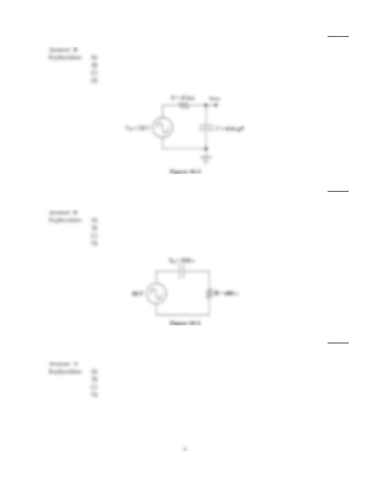
Calculate the voltage drop across the capacitor in Figure 10–1.
5)
A)
14.4 V
B)
3.69 V
C)
11.5 V
D)
4.82 V
6)
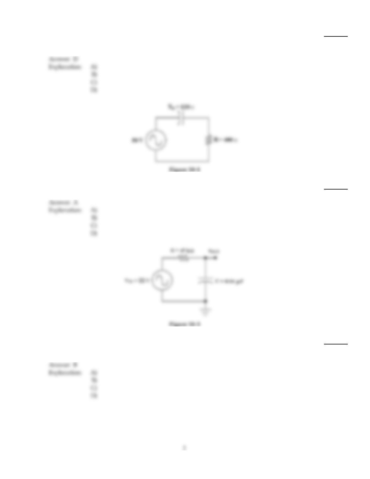
If the circuit in Figure 10–3 has an output voltage that’s too high at the cutoff frequency, ________.
6)
A)
the resistor has shorted
B)
the capacitor has become leaky
C)
the resistor has opened
D)
the capacitor has shorted
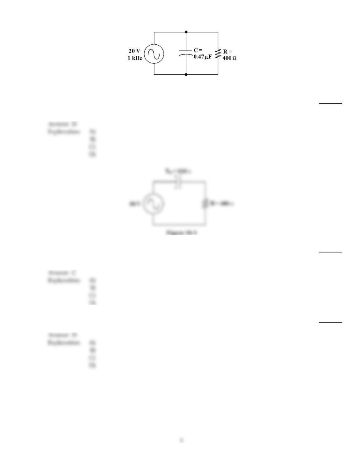
Figure 10–2
7)
If the resistor value increases in Figure 10–2, then how does the total current change?
7)
A)
It remains the same.
B)
It increases.
C)
It decreases to zero.
D)
It decreases.
8)
If the frequency increases in Figure 10–1, the phase angle ________ and the impedance ________.
8)
A)
increases, decreases
B)
increases, increases
C)
decreases, decreases
D)
decreases, increases
9)
If the frequency equals 60 Hz in Figure 10–1, what is the value of capacitance?
9)
A)
88 µF
B)
44 µF
C)
66 µF
D)
22 µF
10)
What is the true power in Figure 10–1?
10)
A)
275 mW
B)
5.73 W
C)
5.73 mW
D)
916 mW
11)
The circuit in Figure 10–3 is known as a ________.
11)
A)
high–pass filter
B)
low–pass filter
C)
band–pass filter
D)
parallel RC circuit
Explanation:
12)
If the operating frequency increases in Figure 10–1, how does the current change?
12)
A)
It increases.
B)
It decreases to zero.
C)
It remains the same.
D)
It decreases.
Explanation:
Explanation:
13)
A power factor of 1 indicates that the circuit phase angle is ________.
13)
A)
180°
B)
90°
C)
45°
D)
0°
14)
If the input voltage increases to 50 V in Figure 10–3, what is the output voltage at the cutoff
frequency?
14)
A)
70.7 V
B)
8.84 V
C)
35.4 V
D)
17.7 V
15)
An RC lag network is similar to a:
15)
A)
band pass filter.
B)
high pass filter.
C)
stop pass filter.
D)
low pass filter.
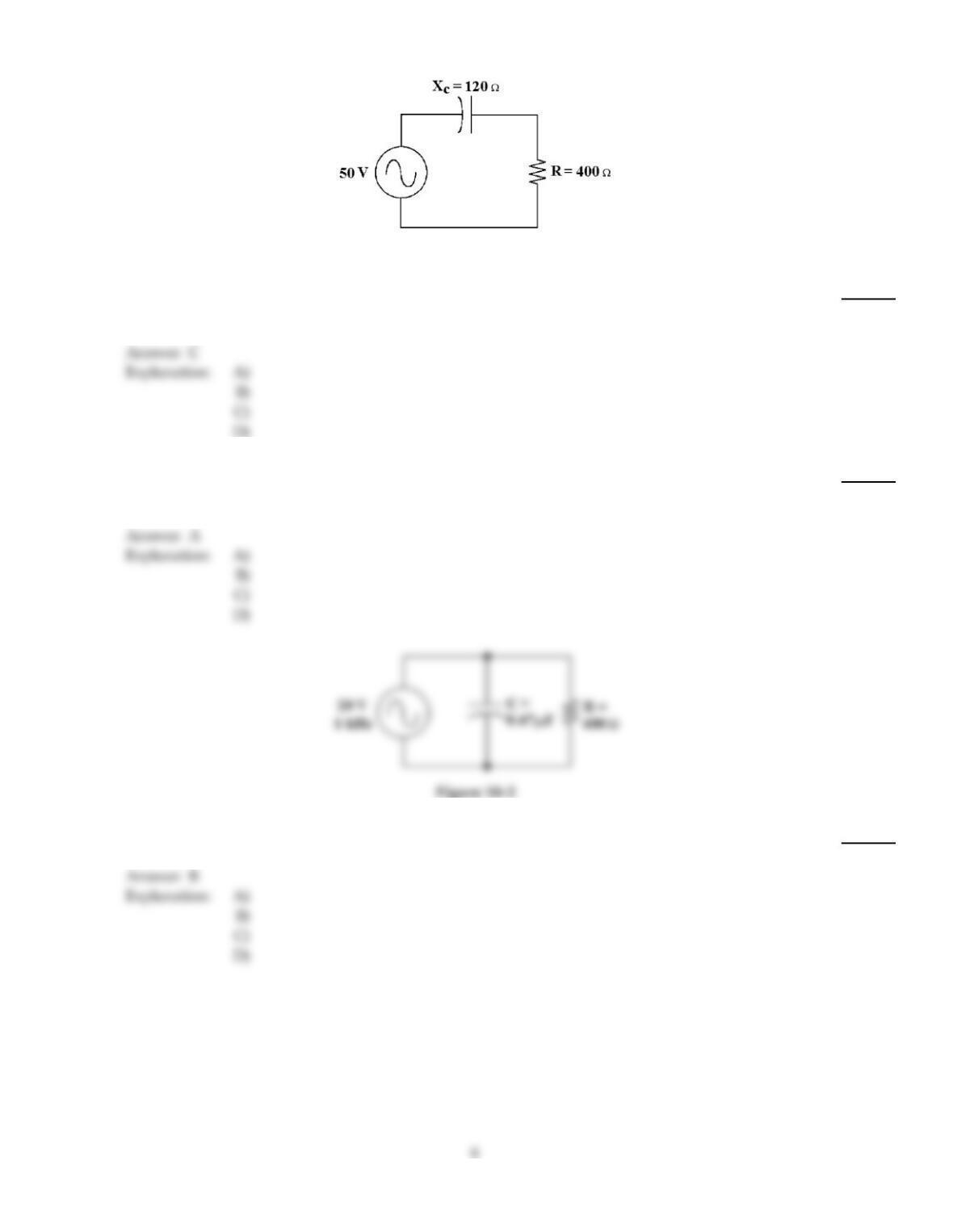
Figure 10–1
16)
If the resistor changes to 2.2 k in Figure 10–1, how does the total current change?
16)
A)
It remains the same.
B)
It increases.
C)
It decreases.
D)
It decreases to zero.
17)
If the operating frequency decreases in Figure 10–1, how does the resistance value change?
17)
A)
It remains the same.
B)
It opens.
C)
It increases.
D)
It decreases.
18)
How much voltage does the resistor drop in Figure 10–2?
18)
A)
19.94 V
B)
20 V
C)
59 mV
D)
10 V
19)
What change would increase the power factor in Figure 10–2?
19)
A)
Decreasing the value of the capacitor
B)
Increasing the value of the resistor
C)
Increasing the value of the capacitor
D)
Increasing the value of the source voltage
20)
If the frequency is 400 Hz in Figure 10–1, what is the value of capacitance?
20)
A)
3.3 µF
B)
8.8 µF
C)
6.6 µF
D)
10 µF
21)
If the source voltage is changed to 100 V in Figure 10–1, find the true power.
21)
A)
3.66 W
B)
22.9 mW
C)
11 W
D)
22.9 W
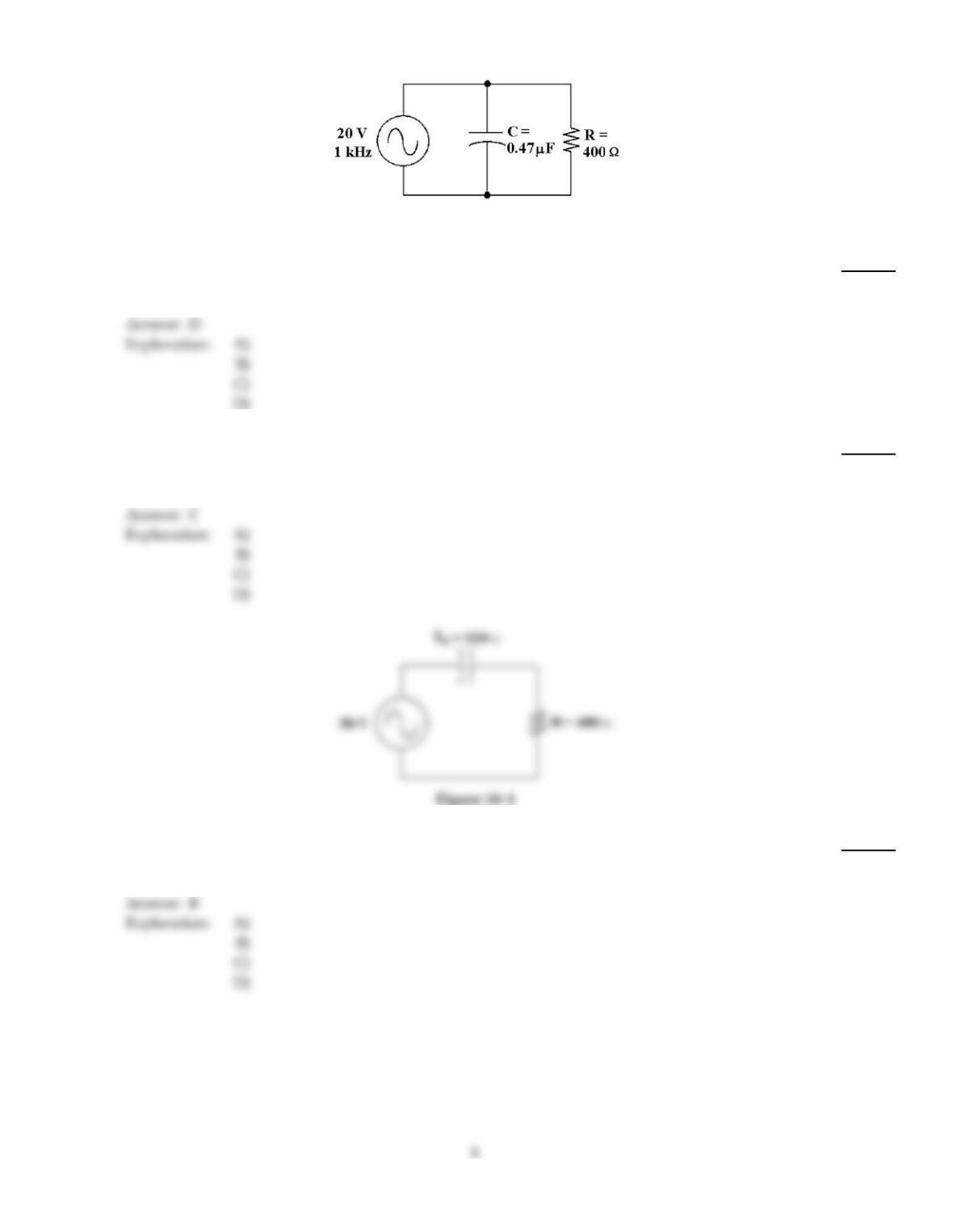
Figure 10–2
22)
What change would decrease the power factor in Figure 10–2?
22)
A)
decreasing the value of the capacitor
B)
increasing the value of the resistor
C)
increasing the value of Vs
D)
increasing the value of the capacitor
23)
Which statement describes the relationship of IC and IR in Figure 10–2?
23)
A)
They are in phase.
B)
IC lags IR.
C)
IC leads IR.
D)
They are 180° out of phase.
24)
If the operating frequency decreases in Figure 10–1, how does the phase angle change?
24)
A)
It changes to another quadrant.
B)
It increases.
C)
It remains the same.
D)
It decreases.
25)
If the operating frequency decreases in Figure 10–1, how does the capacitance value change?
25)
A)
It increases.
B)
It decreases.
C)
It remains the same.
D)
It decreases to zero.
26)
If there is 10 VRMS across the resistor and 10 VRMS across the capacitor in a series RC circuit, then
the source voltage equals ________.
26)
A)
14.1 VRMS
B)
20 VRMS
C)
10 VRMS
D)
28.3 VRMS
27)
What is the output voltage at the cutoff frequency in Figure 10–3?
27)
A)
31.1 V
B)
15.6 V
C)
6.45 V
D)
22 V
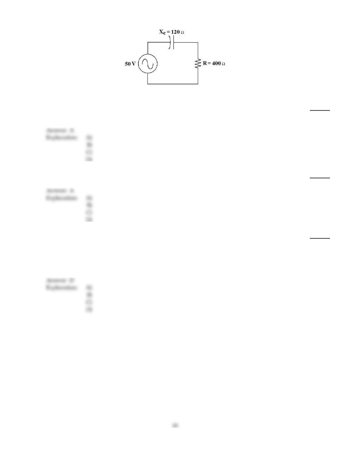
Figure 10–1
28)
If the frequency decreases in Figure 10–1, the phase angle ________ and the impedance ________.
28)
A)
increases, increases
B)
increases, decreases
C)
decreases, increases
D)
decreases, decreases
29)
Simple RC circuits can be viewed as what type of filter?
29)
A)
passive
B)
active
C)
high pass
D)
low pass
30)
It has been determined that the phase shift of a given parallel RC circuit is lower than predicted.
Which of the following most likely has caused this?
30)
A)
The capacitance has decreased.
B)
The function generator frequency control has been accidentally moved to a lower frequency.
C)
Resistance has decreased.
D)
could be A or C
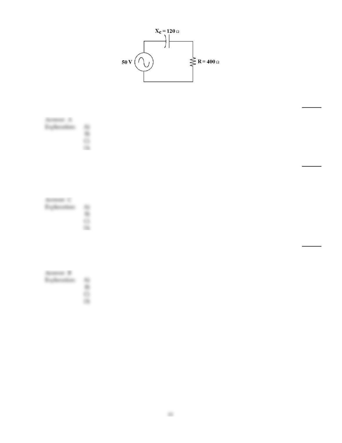
Figure 10–1
31)
What is the circuit’s impedance in Figure 10–1?
31)
A)
418
B)
520
C)
280
D)
120
32)
Which of these troubleshooting procedures should be performed first?
32)
A)
Check test equipment connections.
B)
Take random measurements around point of failure.
C)
Analyze the problem and decide where best to start.
D)
Slap the device firmly to dislodge foreign objects.
33)
In a series RC circuit, as the phase angle between the applied voltage and the total current
increases, this is the same as:
33)
A)
apparent power decreasing.
B)
power factor decreasing.
C)
true power decreasing.
D)
power factor increasing.