1. Engineers use technical drawings to convey useful information to others in a standard manner.
a. True
b. False
2. An engineering drawing provides information, such as the shape of a product, its dimensions,
materials from which to fabricate the product, and assembly steps.
a. True
b. False
3. The views that show what an object’s projection looks like when seen from the top, the front,
and the side are known as
a. isometric views.
b. orthographic views.
c. standard views.
d. normal views.
4. Which three views are most commonly used to describe most objects?
a. top, front, and back
b. front, bottom, and left
c. top, back, and right
d. top, front, and right
5. Hidden lines are used to show
a. the intersection of two planes that are not visible from the direction you are looking.
b. reference locations for the machinist who will be making the part.
c. optional start/stop locations.
d. reference locations for assembly.
6. Solid lines are used to show
a. reference locations for the machinist who will be making the part.
b. the visible edges of planes or the intersection of two planes.
c. optional start/stop locations.
d. reference locations for assembly.
7. Center lines, or lines of symmetry, are used to show
a. reference locations for the machinist who will be making the part.
b. the visible edges of planes or the intersection of two planes.
c. reference locations for assembly.
d. where the center of holes or the center of cylinders are.
8. The number of orthographic views that you should draw to represent an object
a. is always three.
b. is at least three.
c. is at most three.
d. depends on the complexity of the object.
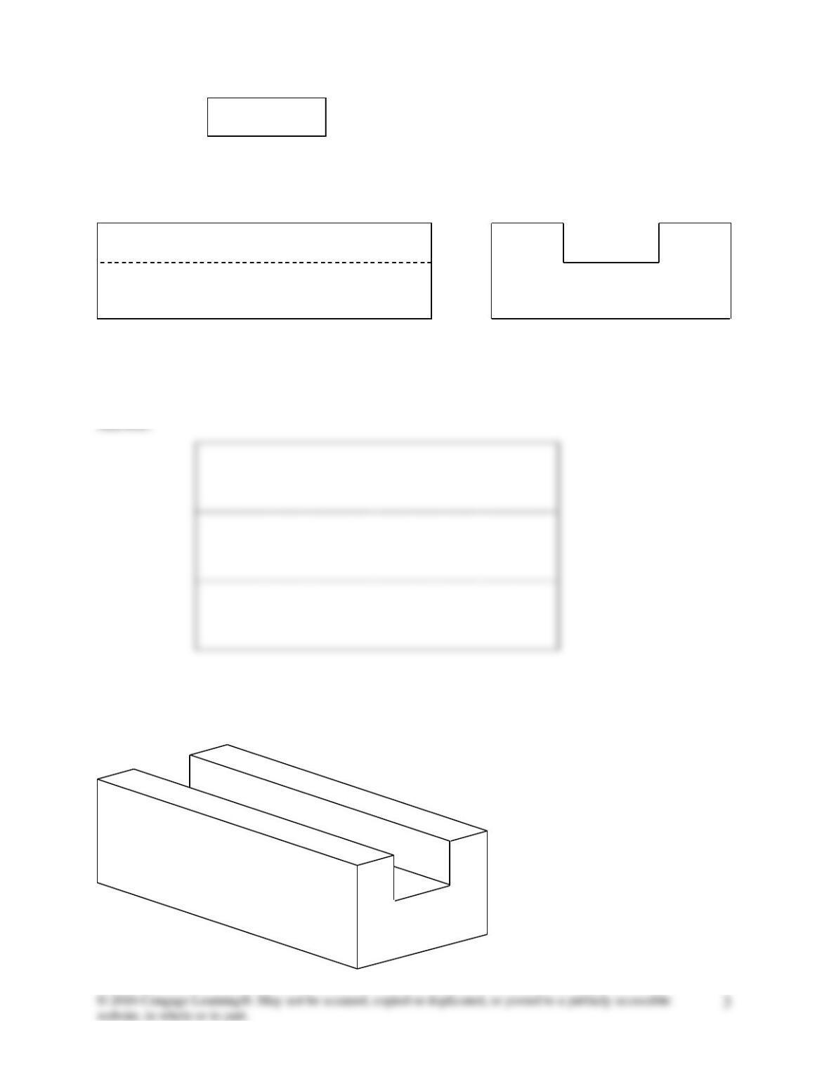
9. Shown below are two orthographic views. Draw the missing view.
Test Bank Engineering Fundamentals, 5th ed. Chapter 16
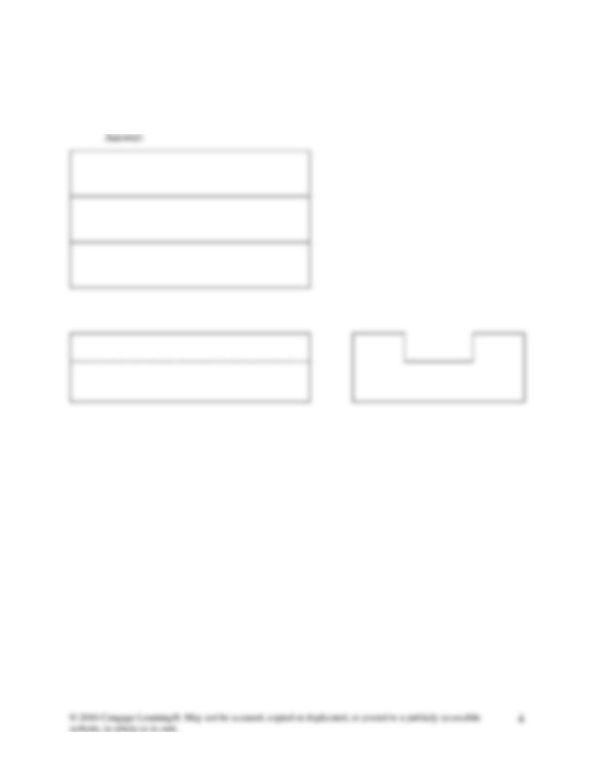
8. Shown below is an isometric drawing. Draw the top, front and right side views.
Missing view
Test Bank Engineering Fundamentals, 5th ed. Chapter 16
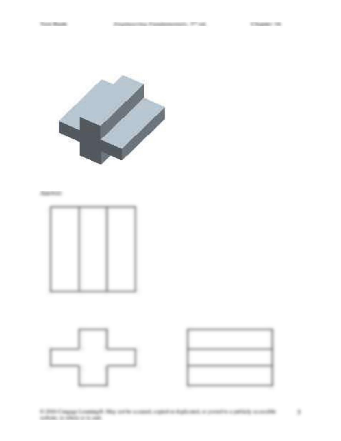
9. Shown below is an isometric drawing. Draw the top, front and right side views.
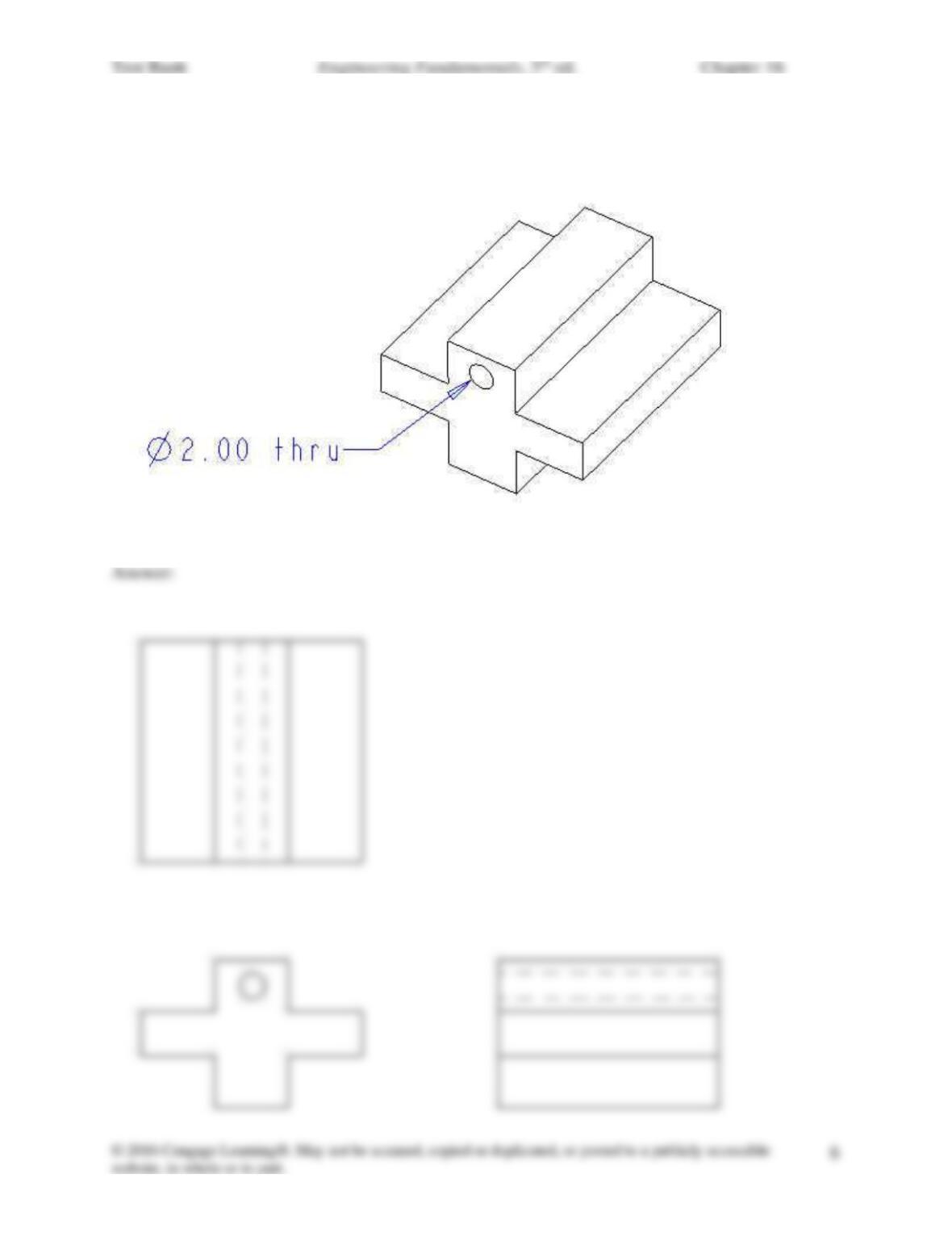
10. Shown below is an isometric drawing. Draw the top, front and right side views.

Test Bank Engineering Fundamentals, 5th ed. Chapter 16
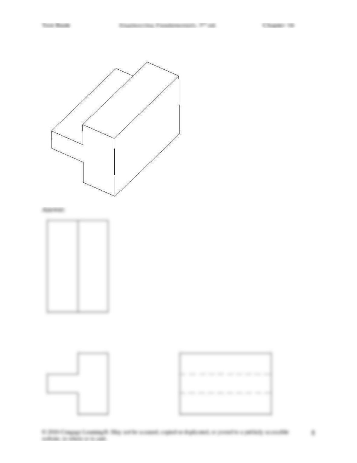
11. Shown below is an isometric drawing. Draw the top, front and right side views.
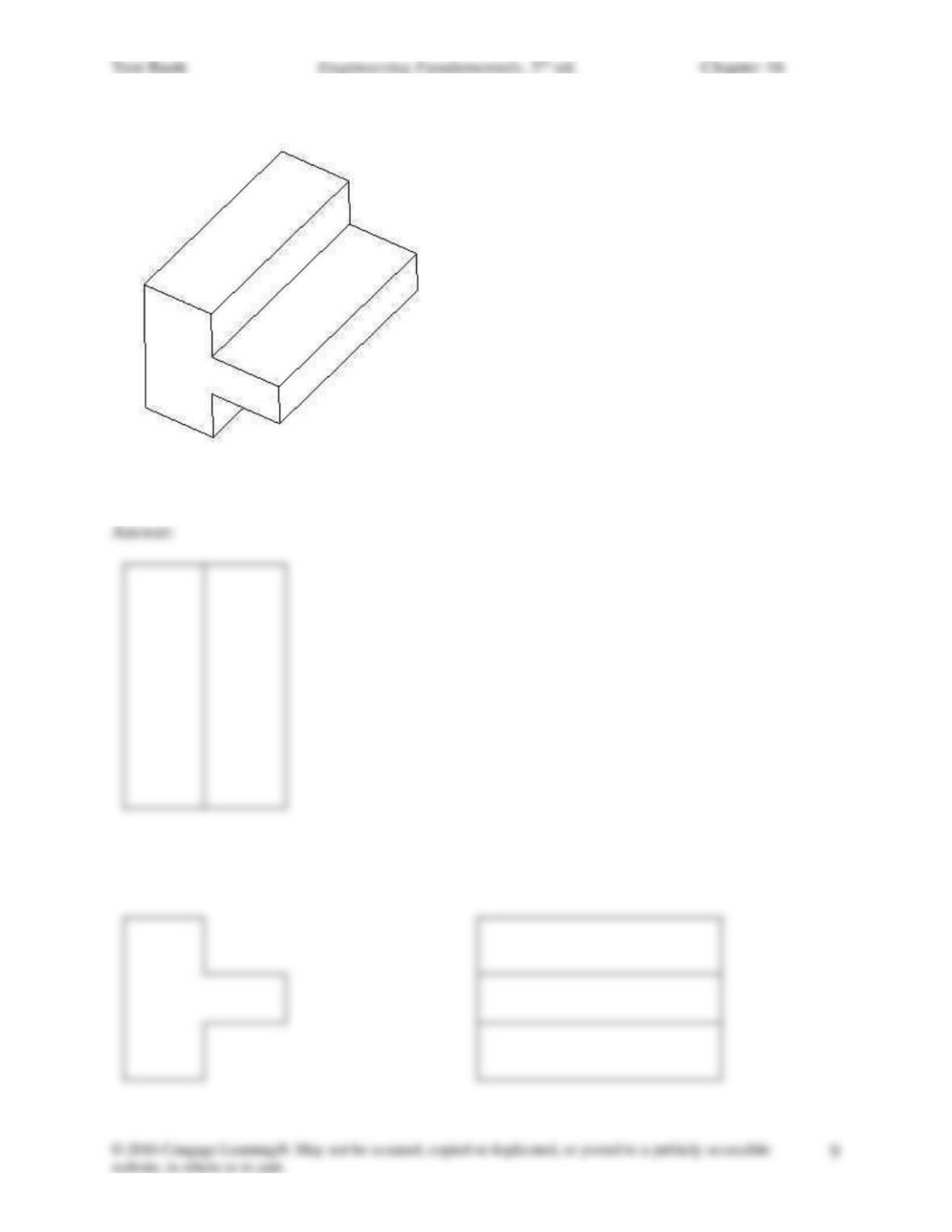
12. Shown below is an isometric drawing. Draw the top, front and right side views.
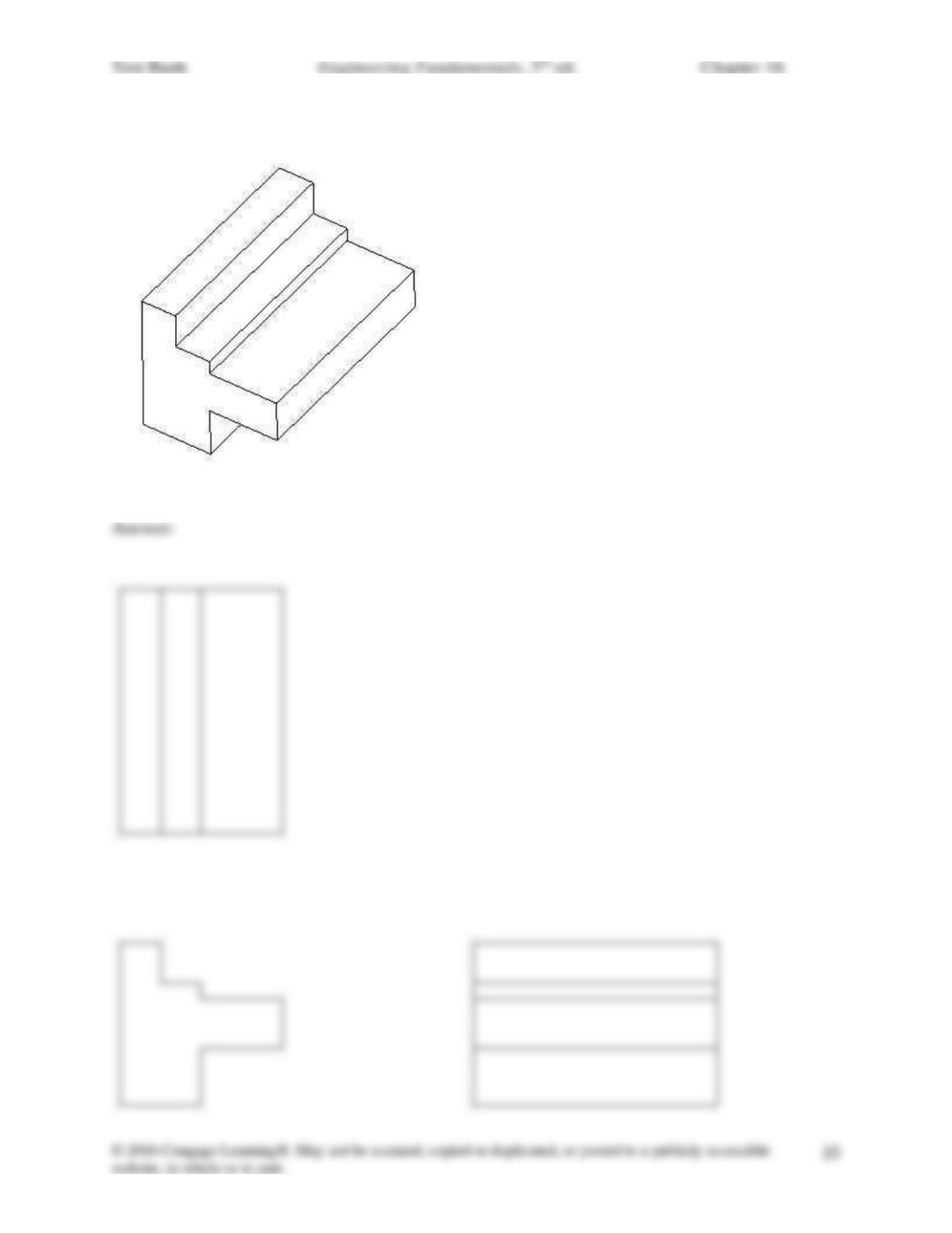
13. Shown below is an isometric drawing. Draw the top, front and right side views.
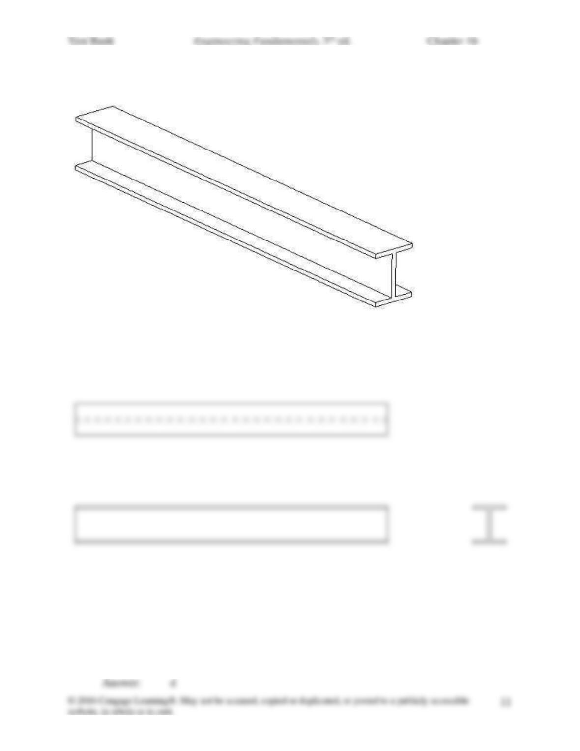
14. Shown below is an isometric drawing. Draw the top, front and right side views.
Answer:
15. Engineering drawings provide information about
a. size, shape, and material of a product.
b. dimensions and tolerances.
c. surface finish and part number(s).
d. all of the above
16. There are basically two concepts that you need to keep in mind when specifying dimensions
in an engineering drawing:
a. size and location.
b. size and material.
c. size and tolerance.
d. part number and material.
17. An engineering drawing is dimensioned with the aid of
a. dimension lines.
b. extension lines.
c. centerlines and leaders.
d. all of the above
18. The lines that provide information on the size of the object; for example, how wide it is and
how long it is are known as
a. dimension lines
b. extension lines
c. leaders
d. none of the above
19. The lines that extend from the points to which the dimension or location is to be specified are
known as
a. dimension lines
b. extension lines
c. leaders
d. none of the above
20. The arrows that point to a circle or a fillet for the purpose of specifying their sizes are known
as
a. dimension lines
b. extension lines
c. leaders
d. none of the above
21. On an engineering drawing, what does NTS typically stand for?
a. non-technical symbol
b. not to scale
c. nearest to scale
d. national trade symbol
22. The view that shows the three dimensions of an object in a single view is known as
a. isometric view.
b. orthographic view.
c. standard view.
d. normal view.
23. The view that shows the solid portions and the voids within the object are known as
a. isometric view.
b. orthographic view.
c. standard view.
d. sectional view.
24. In a sectional view, the solid portion of the view is marked with
a. cross-hatching.
b. shading.
c. hidden lines.
d. rendering.
25. Which of the following are components of a sectional view?
a. cutting plane
b. directional arrow
c. cross-hatching
d. all of the above
26. AutoCAD, IDEAS, and Pro-E/Creo are examples of
a. solid modeling software.
b. civil engineering drawings.
c. electrical drawings.
d. electronic drawings.
27. CNC machines are often used to make parts directly from solid modeling software. What
does CNC stand for?
a. central navigation center
b. computer navigation center
c. computer nominally controlled
d. computer numerically controlled
28. The American National Standards Institute (ANSI) does not set the standards for the
dimensioning and tolerancing practices for engineering drawings.
a. True
b. False
29. A machinist must be able to make the part from the detailed drawings without needing to go
back to the engineer or the draftsperson who drew the drawings to ask questions regarding the
size, or the tolerances, or what type of material the part should be made from.
a. True
b. False
30. For objects with complex interiors, sectional views are used. Sectional views reveal the
inside of the object.
a. True
b. False
31. A sectional view is created by making an imaginary cut through the object, in a certain
direction, to reveal its interior.
a. True
b. False
32. Half-section views are created when the cutting plane passes through the object completely.
a. True
b. False
33. The computer-generated solid models save time and money and allow the engineer to
perform additional engineering analysis, such as stress calculations or temperature distribution
calculations for products.
a. True
b. False
34. Engineers use conventional engineering symbols as a means to convey information and to
effectively communicate to other engineers.
a. True
b. False
35. Electrical engineers use various symbols to represent the components that make up
a. a television set
b. a smart phone
c. a computer
d. a printer
e. all of the above
36. Mechanical engineers use engineering symbols in their diagrams to show the
a. layout of piping networks in buildings
b. placement of air supply ducts
c. placement of air return ducts
d. fans and heating and cooling units
e. all of the above
37. There are two ways to create a solid model of an object. What are they?
_____________
_______________
38. The type of drawings that is common to civil engineering include land or boundary,
topographic, construction, connection and reinforcement details, and route survey drawings.
a. True
b. False
39. Rotated section views may be used when the object has a uniform cross section with a shape
that is difficult to visualize. In such cases, the cross section is rotated by 90° and is shown in the
plane of view.
a. True
b. False
40. It is not necessary for all engineering drawings to contain an information box with the
following items: name of the person who prepared the drawing, title of the drawing, date, scale,
sheet number, and drawing number.
a. True
b. False