22)
A decade counter counts from zero (0) through decimal ________.
22)
A)
10
B)
0
C)
9
D)
15
23)
Which of the following procedures would be used to check the parallel loading feature on a
counter?
23)
A)
Apply HIGHs to all the DATA inputs, pulse the CLK and CLR inputs, and check to be sure
that the Q outputs are all LOW.
B)
Apply LOWs to the parallel DATA inputs, pulse the CLK input and check for LOWs on all
the Q outputs.
C)
Preset the LOAD inputs, set the CLR to its active level and check to see that the Q outputs
match the values preset into the LOAD inputs.
D)
Apply HIGHs to all the Q terminals, pulse the CLK and check to see if the DATA terminals
now match the Q outputs.
B
24)
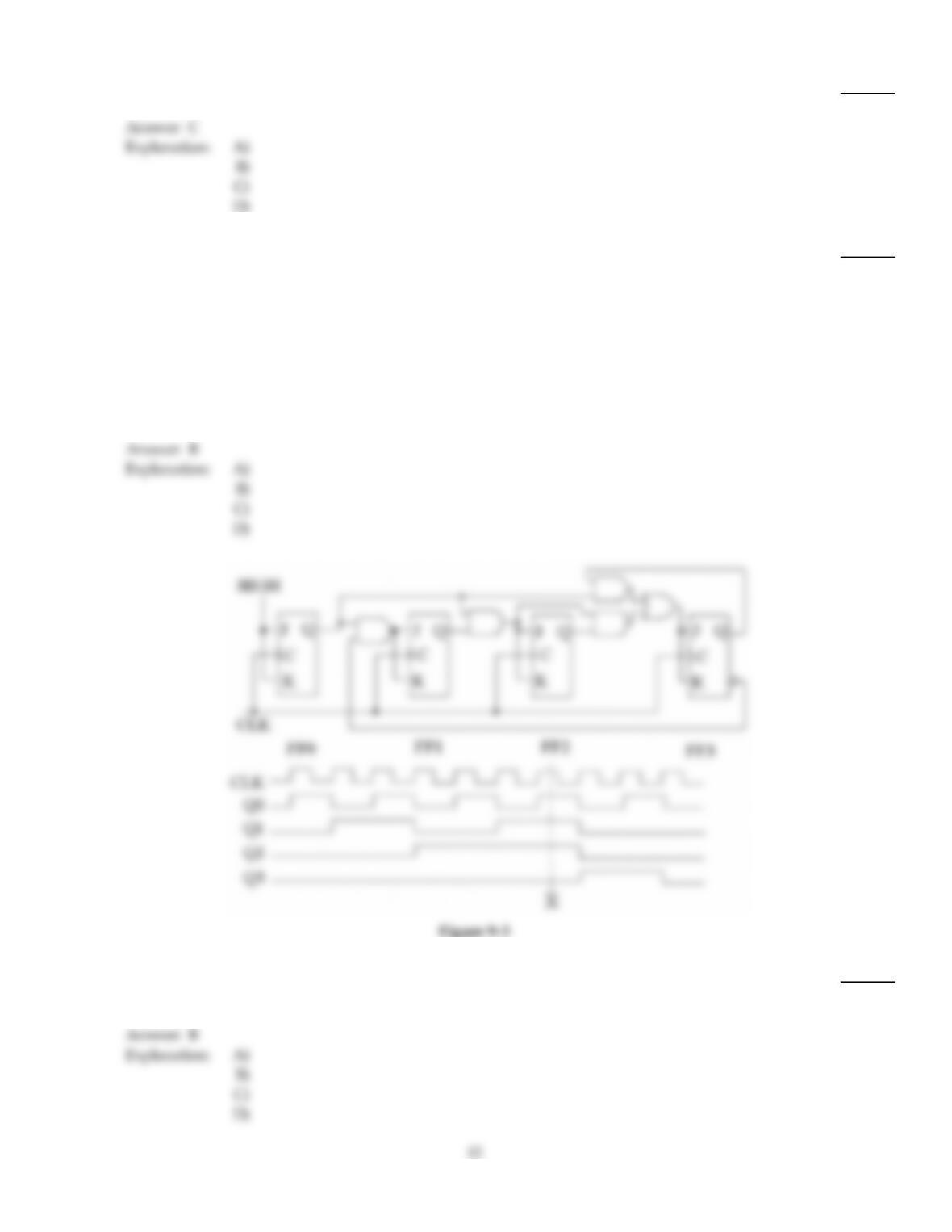
The circuit shown in Figure 9–3 represents a(n) ________.
24)
A)
four–bit binary counter
B)
synchronous BCD decade counter
C)
asynchronous BCD decade counter
D)
BCD–to–decimal decoder
B
C
25)
Which type of state machine has a clock input?
25)
A)
State machines do not have clock inputs.
B)
Moore
C)
Mealy
D)
Moore and Mealy
26)
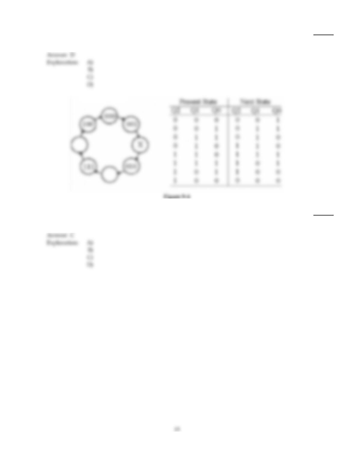
If the diagram shown in Figure 9–6 represents a three–bit Gray code counter, what binary value
would exist at ‘X’?
26)
A)
010
B)
101
C)
011
D)
110
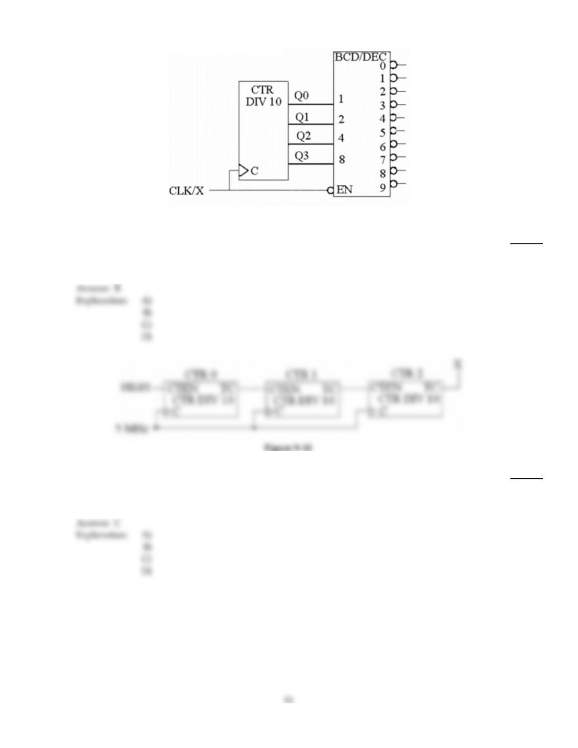
Figure 9–10
27)
The ‘X’ in the CLK/X input in Figure 9–10 is normally called the ________, and, in this example, is
an active ________ level.
27)
A)
STROBE, HIGH
B)
STROBE, LOW
C)
NOT CLOCK, LOW
D)
ENABLE, HIGH
28)
The circuit in Figure 9–11 is used for ________ and for the inputs shown, the DATA OUT will be
________.
28)
A)
parallel–to–serial conversion, HIGH
B)
multiplexing, 1
C)
parallel–to–serial conversion, 0
D)
demultiplexing, 0
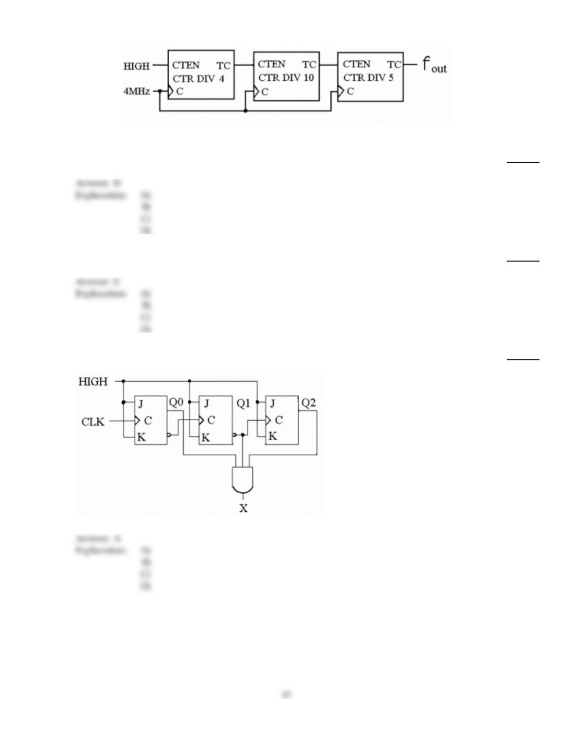
Figure 9–9
29)
What is the modulus of the counter shown in Figure 9–9?
29)
A)
0.005
B)
19
C)
5000
D)
200
30)
Asynchronous counters are often called ________ counters.
30)
A)
flip–flop
B)
toggle
C)
ripple
D)
binary
31)
What decimal value is required to produce an output at ‘X’ in this circuit?
31)
A)
5
B)
1 or 4
C)
1
D)
2
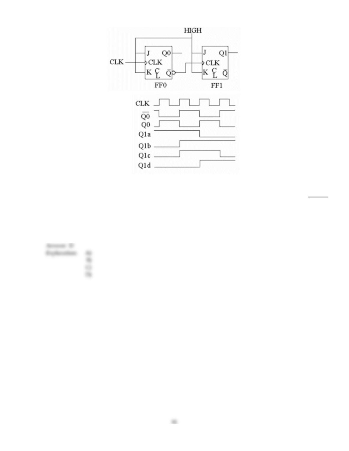
Figure 9–1
32)
An oscilloscope indicates that the circuit in Figure 9–1 has no Q1 output signal. All J–K inputs are
HIGH, the CLK signal is present and Q0 is toggling. The C input of FF1 is a constant LOW. What
could be causing the problem?
32)
A)
The Q0 output should be connected to the J input of FFl.
B)
The input of FF1 may be shorted to ground.
C)
The output of FF0 may be shorted to ground.
D)
The problem could be caused by either B or C.
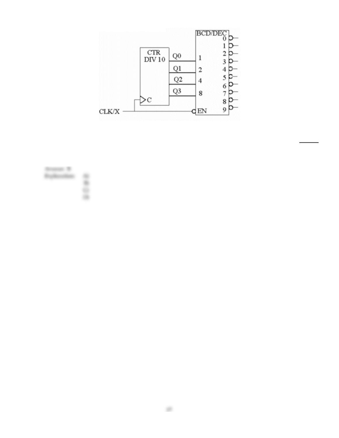
Figure 9–10
33)
The purpose of the connection between ‘C’ of the ‘CTR DIV 10′ circuit and the ‘EN’ of the
‘BCD/DEC’ circuit in Figure 9–10 is to ________ and is referred to as ________.
33)
A)
speed up the counter, strobing
B)
eliminate glitches, strobing
C)
clock the counter, strobing
D)
reduce the number of inputs, enabling
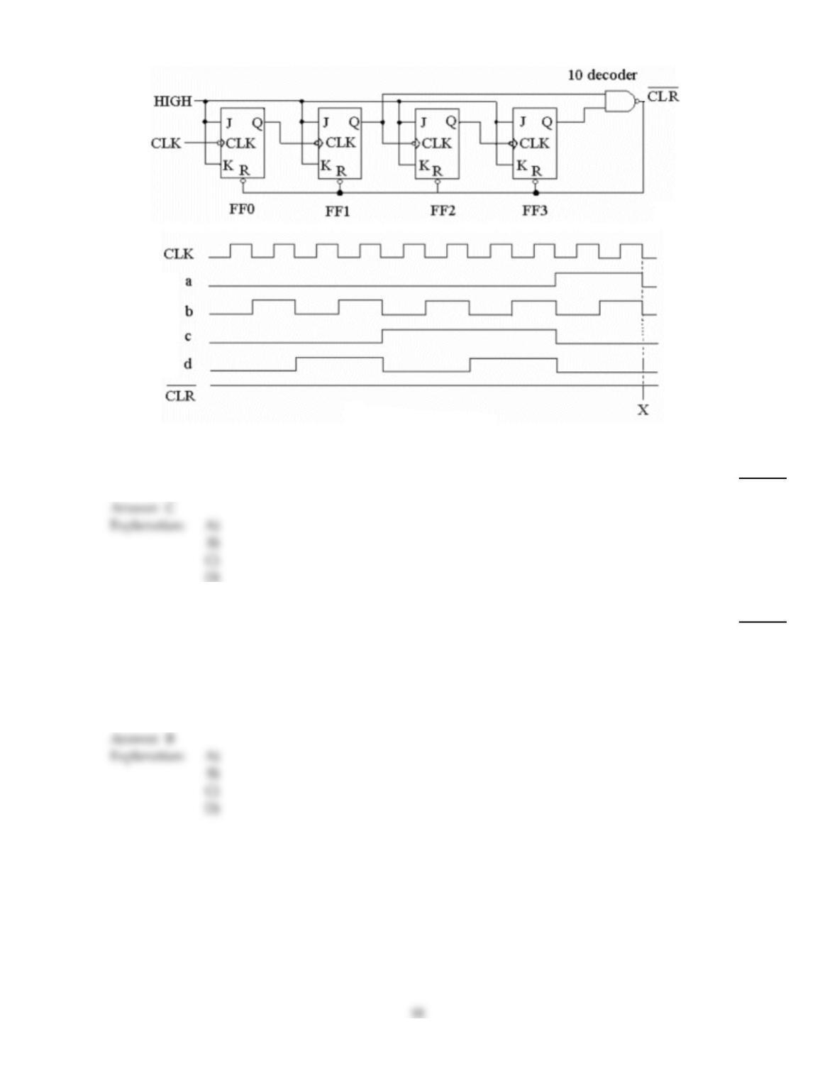
Figure 9–2
34)
Which of the waveforms shown in Figure 9–2 represents the output of FF2?
34)
A)
Waveform a
B)
Waveform b
C)
Waveform c
D)
Waveform d
35)
Which of the following statements best describes the operation of an UP/DOWN SYNCHRONOUS
COUNTER?
35)
A)
The counter can be reversed, but must be RESET before counting in the other direction.
B)
In general, the counter can be reversed at any point in its counting sequence.
C)
The counter can count in either direction, but must continue in that direction once started.
D)
The count sequence cannot be reversed, once it has begun, without first resetting the counter
to zero.

36)
In order to check the CLR function of a counter, which action should be taken?
36)
A)
Apply the active level to the CLR input and check all of the Q outputs to see if they are all in
their reset state.
B)
Ground the CLR input and check to be sure that all of the Q outputs are LOW.
C)
Connect the CLR to its correct active level while clocking the counter; check to make sure that
all of the Q outputs are toggling.
D)
Connect the CLR input to Vcc and check to see if all of the Q outputs are HIGH.
37)
What is the significance of the Xs in the Karnaugh map shown in Figure 9–7?
37)
A)
They may be grouped with either the ones or the zeroes in the Karnaugh map.
B)
They can represent either ones or zeroes, as long as they are all the same.
C)
They must all be grouped together to form an output equation.
D)
They represent ‘don‘t care’ states.
38)
The logic expression for the Karnaugh map in Figure 9–7 is ________.
38)
A)
Q2Q0
B)
Q1Q0
C)
Q2Q1Q0
D)
Q2Q1
TRUE/FALSE. Write ‘T’ if the statement is true and ‘F’ if the statement is false.
39)
Another term used to describe up/down counters is bidirectional.
39)
40)
The dot extension .CLK is used to indicate that the register device is a clocked flip–flop.
40)
41)
The register output expression Q0=D0 indicates that the output Q0 will assume the value of the
D0 input on the clock pulse.
41)
42)
In many cases, counters must be strobed in order to eliminate glitches.
42)
43)
Most sequential circuits contain a combinational logic section and a memory section.
43)
44)
A state machine has a finite number of states that occur in random order.
44)
45)
The output from a Mealy state machine depends on its internal state and on external inputs.
45)
46)
Basic counters can be cascaded to increase the number of count states the counter can produce.
46)
47)
The term synchronous refers to events that do not occur at the same time.
47)
48)
Counters are generally decoded in order to determine their count state.
48)
49)
The term synchronous as applied to counter operations means that the counter is clocked so that
each flip–flop in the counter is triggered at the same time.
49)
50)
A Moore state machine does not have a clock input.
50)
51)
Once an up/down counter begins its count sequence, it cannot be reversed.
51)
Answer Key
Testname: C9

Answer Key
Testname: C9