Exam
Name___________________________________
MULTIPLE CHOICE. Choose the one alternative that best completes the statement or answers the question.
1)
When performing superposition to analyze acircuit, series–parallel circuit analysis
1)
A)
cannot be used to analyze the circuit for each source.
B)
can only be used to determine the phasor voltage in the circuit for each source.
C)
can be used to analyze the circuit for each source.
D)
can only be used to determine the phasor current in the circuit for each source.
2)
In aseries circuit
2)
A)
the current divider rule can be used.
B)
voltage division occurs.
C)
the voltage divider rule cannot be used.
D)
current division occurs.
B
3)
In superposition, a voltage source is deactivated by
3)
A)
replacing it with azero–current current source to guarantee zero voltage.
B)
removing the source and replacing it with ashort to guarantee zero voltage.
C)
removing the source and replacing it with an open to guarantee zero voltage.
D)
placing ashort circuit across it to guarantee zero voltage.
B
4)
In parallel circuits
4)
A)
voltage division occurs.
B)
the total current is the sum of the current in the individual branches.
C)
the current divider rule cannot be used.
D)
voltage divider rule cannot be used.
B
C
5)
In aparallel circuit
5)
A)
the sum of the phasor currents entering and leaving anode must equal zero.
B)
Kirchhoff’s Current Law applies.
C)
the voltage is the same throughout.
D)
All of the above
6)
Superposition
6)
A)
can be used in circuit analysis if the source frequencies are different.
B)
can be used in circuit analysis only if the source frequencies are the same.
C)
can be used to determine the voltage across an individual element but cannot be used to
determine the total circuit response.
D)
cannot be used if there are both current sources and voltage sources in the same circuit.
B
7)
Superposition is the
7)
A)
division of the corresponding phasor voltages and currents due to each source in the circuit.
B)
addition (with proper sign) of the corresponding phasor voltages and currents due to each
source in the circuit.
C)
multiplication of the corresponding phasor voltages and currents due to each source in the
circuit.
D)
subtraction of the corresponding phasor voltages and currents due to each source in the
circuit.
B
8)
The model of apractical AC voltage source is an ideal
8)
A)
current source in series with an internal impedance.
B)
voltage source in series with an internal impedance.
C)
voltage source in parallel with an internal impedance.
D)
current source in parallel with an internal impedance.
B
D
9)
The total admittance of aparallel circuit is
9)
A)
one over the sum of the impedances.
B)
one over the sum of the individual admittances.
C)
the total phasor voltage divided by the total phasor current.
D)
one over the total phasor voltage divided by the total phasor current.
10)
Kirchhoff’s Voltage Law (KVL) states that
10)
A)
the sum of the phasor voltages around any closed path does not have to equal zero.
B)
the product of the phasor voltages around any closed path must equal zero.
C)
the sum of the phasor voltages around any closed path must equal zero.
D)
the sum of the phasor voltages around aclosed path cannot include “through the air.”
11)
Admittance is
11)
A)
only useful in series circuits.
B)
the phasor current divided by the phasor voltage.
C)
the phasor voltage divided by the phasor current.
D)
None of the above
12)
In superposition, acurrent source is deactivated by
12)
A)
removing the source and replacing it with an open to guarantee zero current.
B)
placing ashort circuit across the source to guarantee zero current in the rest of the circuit.
C)
breaking all connections in the circuit to guarantee zero current.
D)
replacing it with azero–voltage voltage source to guarantee zero current.
13)
In series–parallel circuits
13)
A)
KVL can be applied and is useful.
B)
series–parallel analysis techniques can be applied.
C)
KCL can be applied and is useful.
D)
All of the above
E)
None of the above
14)
The total impedance in aseries circuit is
14)
A)
found by multiplying the complex impedances of each element.
B)
the sum of the individual admittances.
C)
the sum of the individual impedances.
D)
the reciprocal of the sum of the individual impedances.
C
15)
Because the current is the same throughout aseries circuit
15)
A)
the phasor voltage is the same across each element.
B)
the total admittance is the sum of the individual admittances.
C)
the total impedance is the reciprocal of the sum of the individual admittances.
D)
the sum of the phasor voltages around aseries circuit is zero.
D
16)
The model of apractical AC current source is an ideal
16)
A)
voltage source in series with an internal impedance.
B)
current source in parallel with an internal impedance.
C)
voltage source in parallel with an internal impedance.
D)
current source in series with an internal impedance.
B
D
SHORT ANSWER. Write the word or phrase that best completes each statement or answers the question.
17)
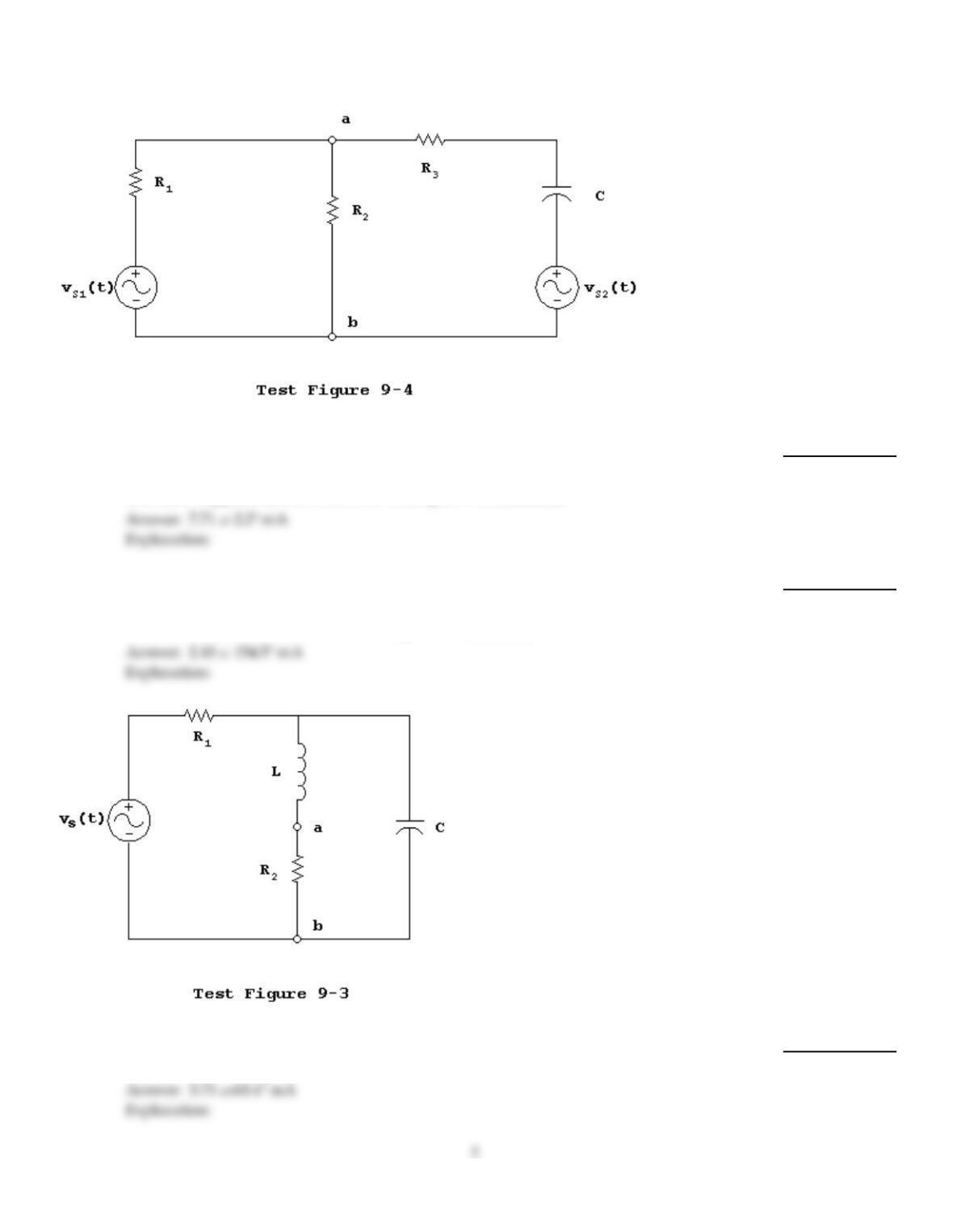
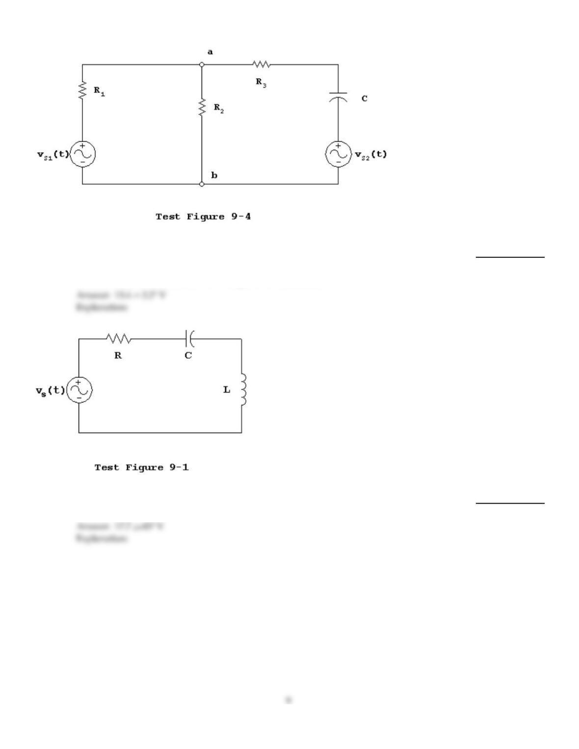
Assume that vs1(t) = 35.355sin(1000t), vs2(t) = 14.142sin(1000t + 45°),R1 = 1.0 k, R2 = 2.0
k, R3 = 2.0 k,and XC = 5.0 k. The total RMS current through R2from terminal ato
terminal bsupplied by both sources of Test Figure 9-4 is ________.
17)
18)
Assume that vs1(t) = 35.355sin(1000t), vs2(t) = 14.142sin(1000t + 45°),R1 = 1.0 k, R2 = 2.0
k, R3 = 2.0 k,and XC = 5.0 k. The RMS current through the capacitor in the direction
from the source S2 to terminal aof Test Figure 9-4 is ________.
18)
19)
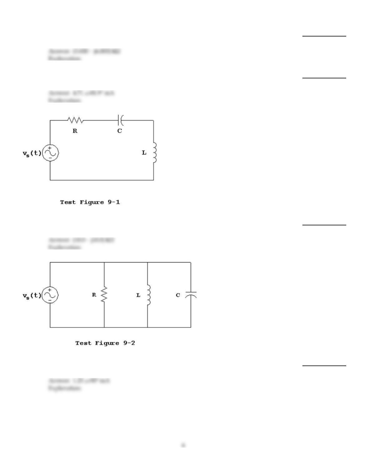
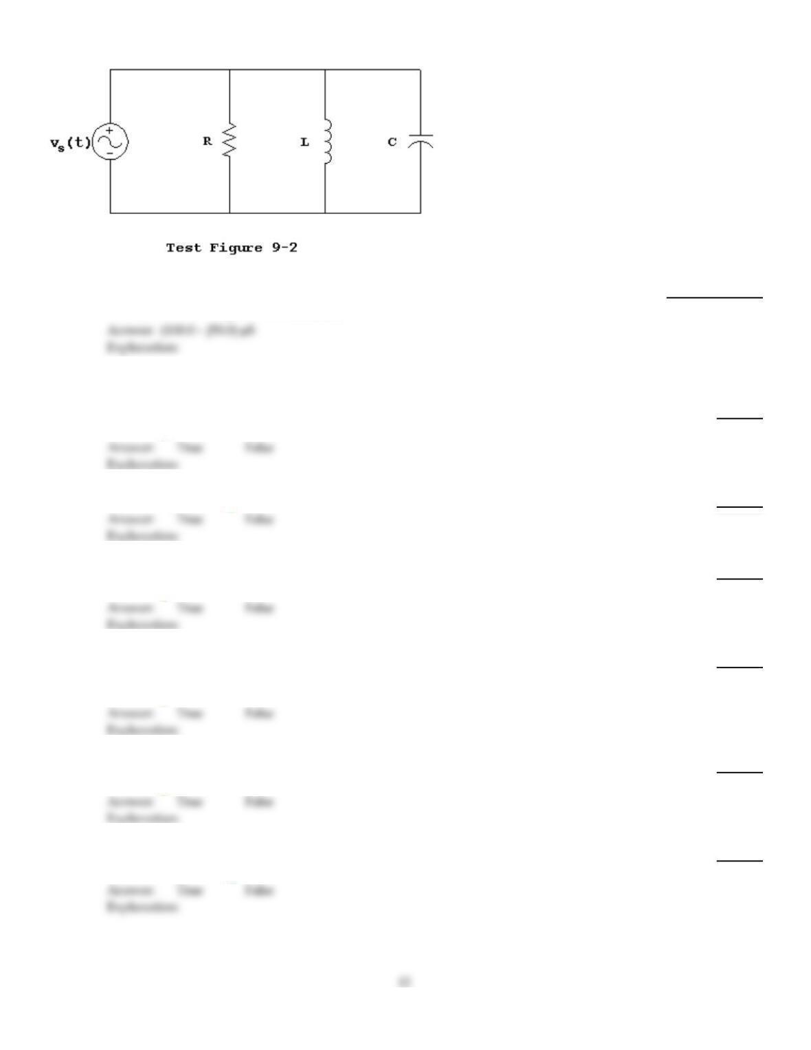
Assume that vs(t) = 35.355sin(1000t), R1 = 1.0 k, R2 = 10.0 k, XC = 5.0 k,and XL = 10.0
k. The total RMS current supplied by the source of Test Figure 9-3 is ________.
19)
20)
Assume that vs(t) = 35.355sin(1000t), R1 = 1.0 k, R2 = 10.0 k, XC = 5.0 k,and XL = 10.0
k. The total impedance for the circuit of Test Figure 9-3 is ________.
20)
21)
Assume that vs(t) = 35.355sin(1000t), R1 = 1.0 k, R2 = 10.0 k, XC = 5.0 k,and XL = 10.0
k. The RMS current through the capacitor of Test Figure 9-3 is ________.
21)
22)
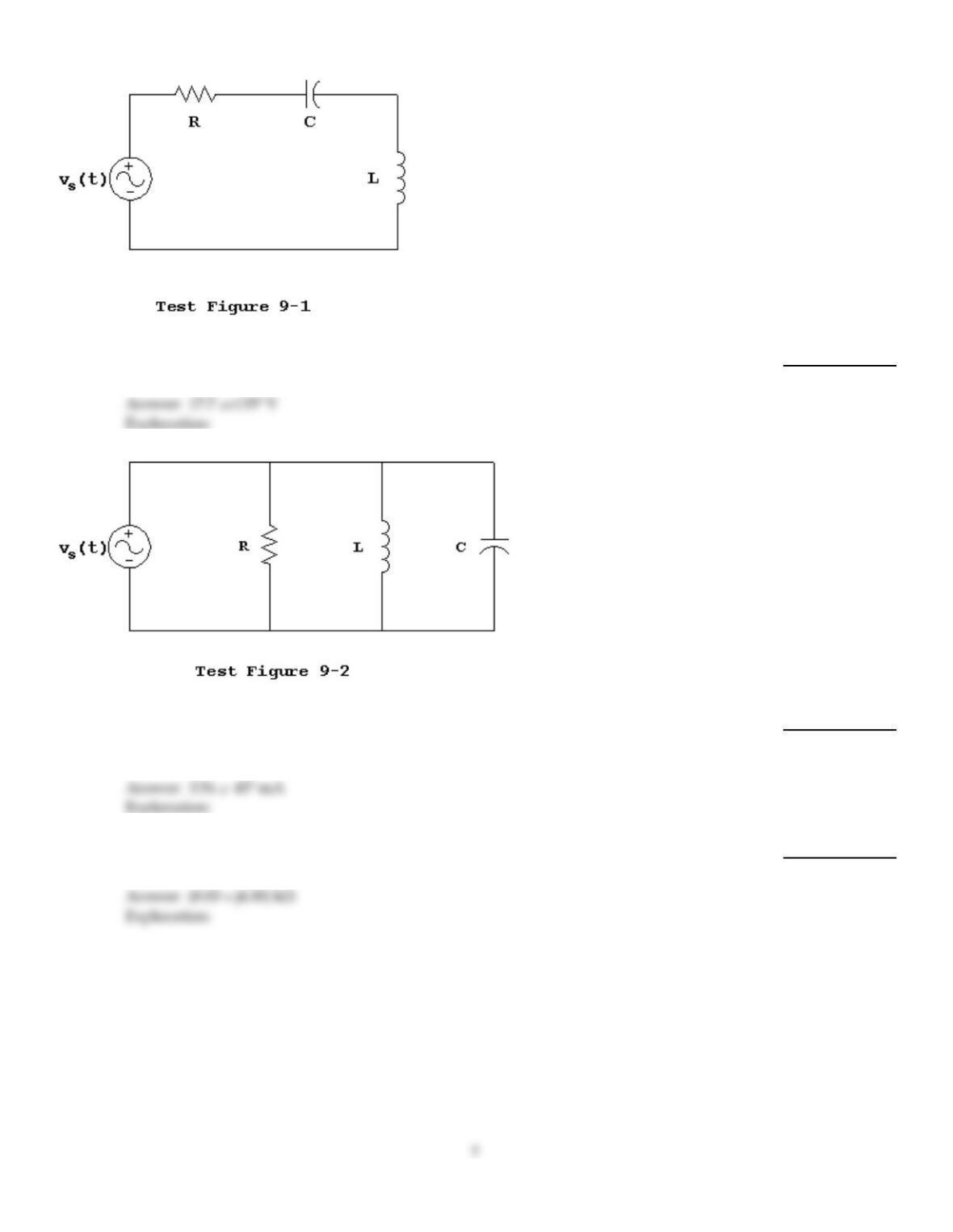
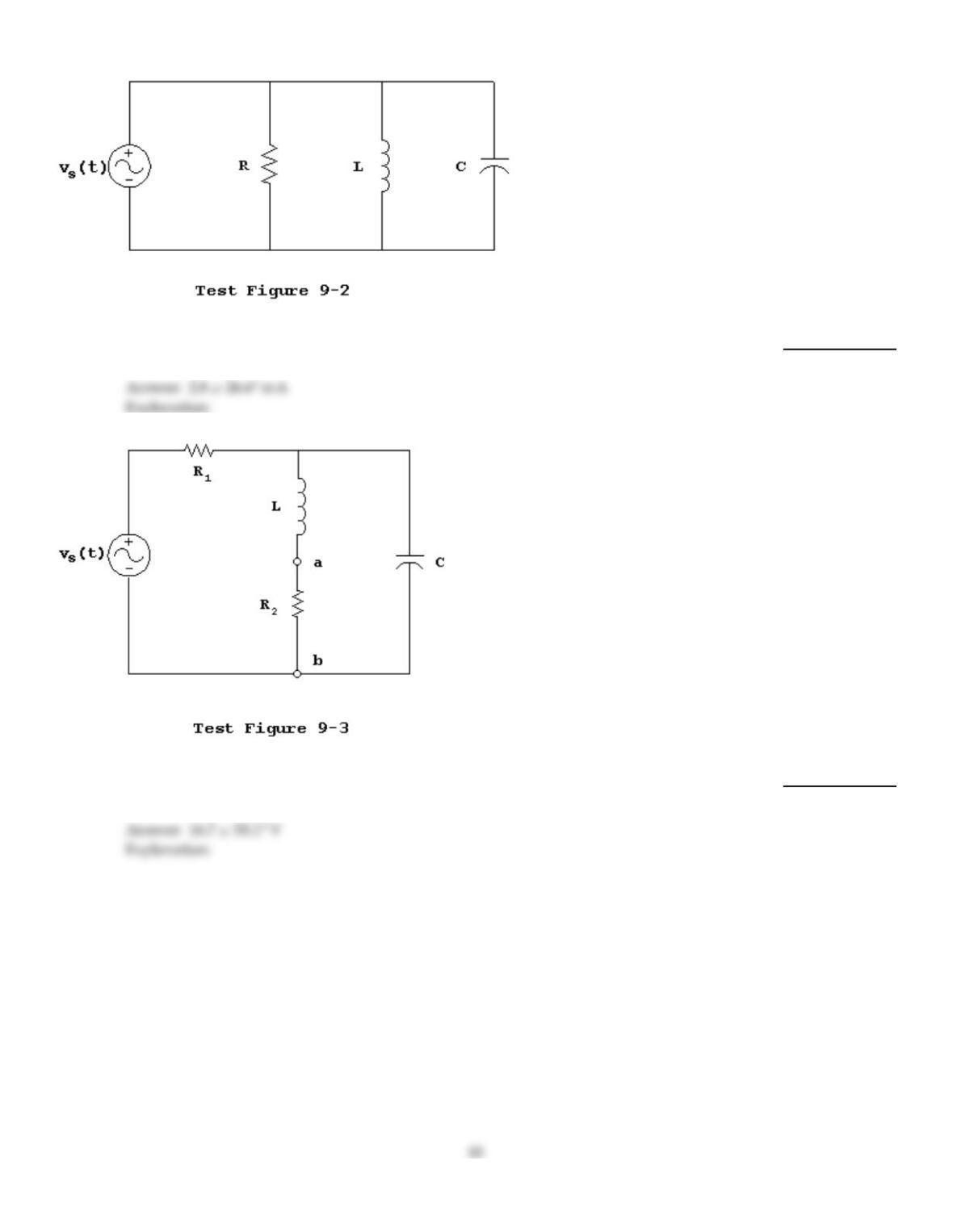
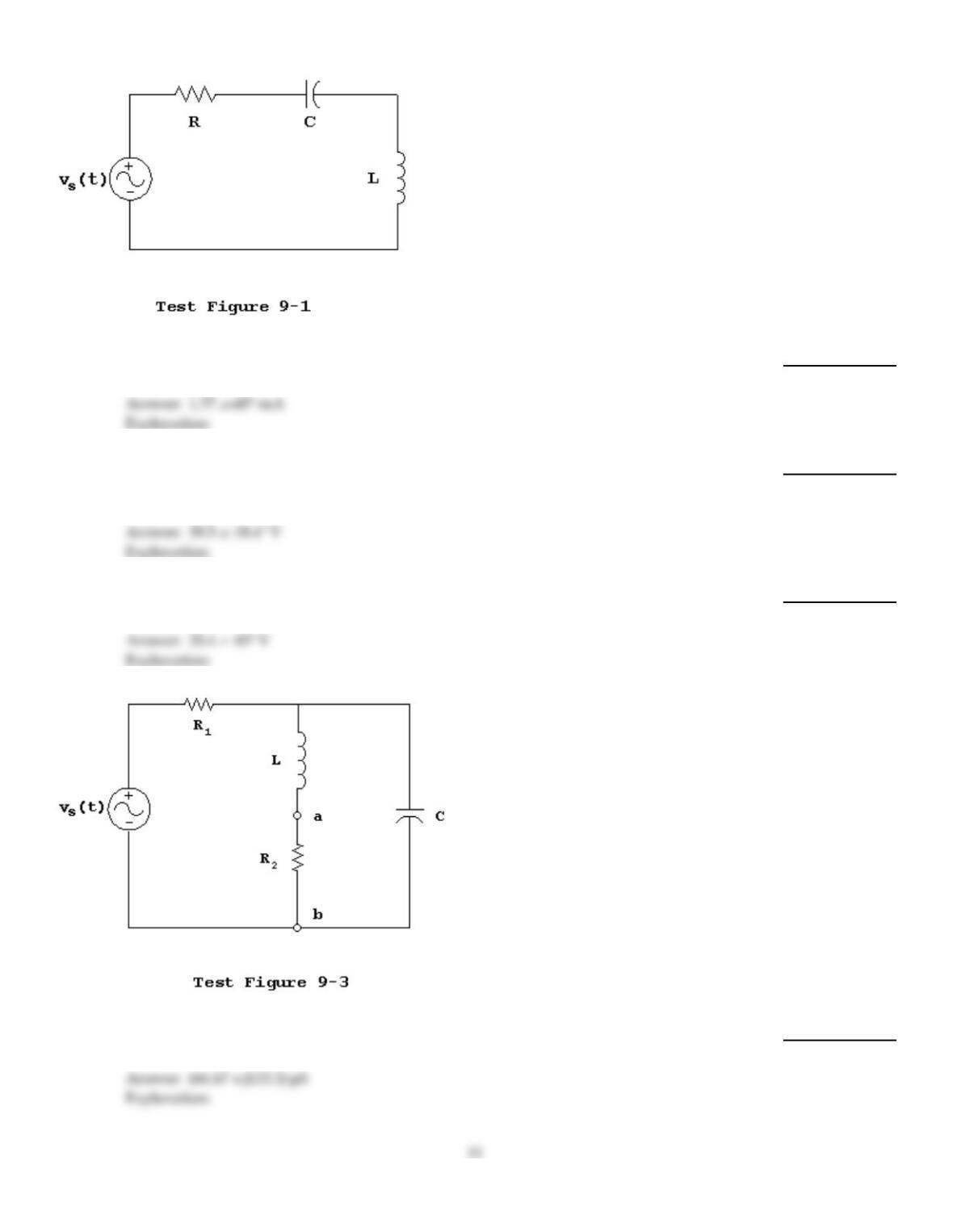
Assume that vs(t) = 35.355sin(1000t), R = 10 k, XC = 20 k,and XL = 10 k. The total
impedance of Test Figure 9-1 is ________.
22)
23)
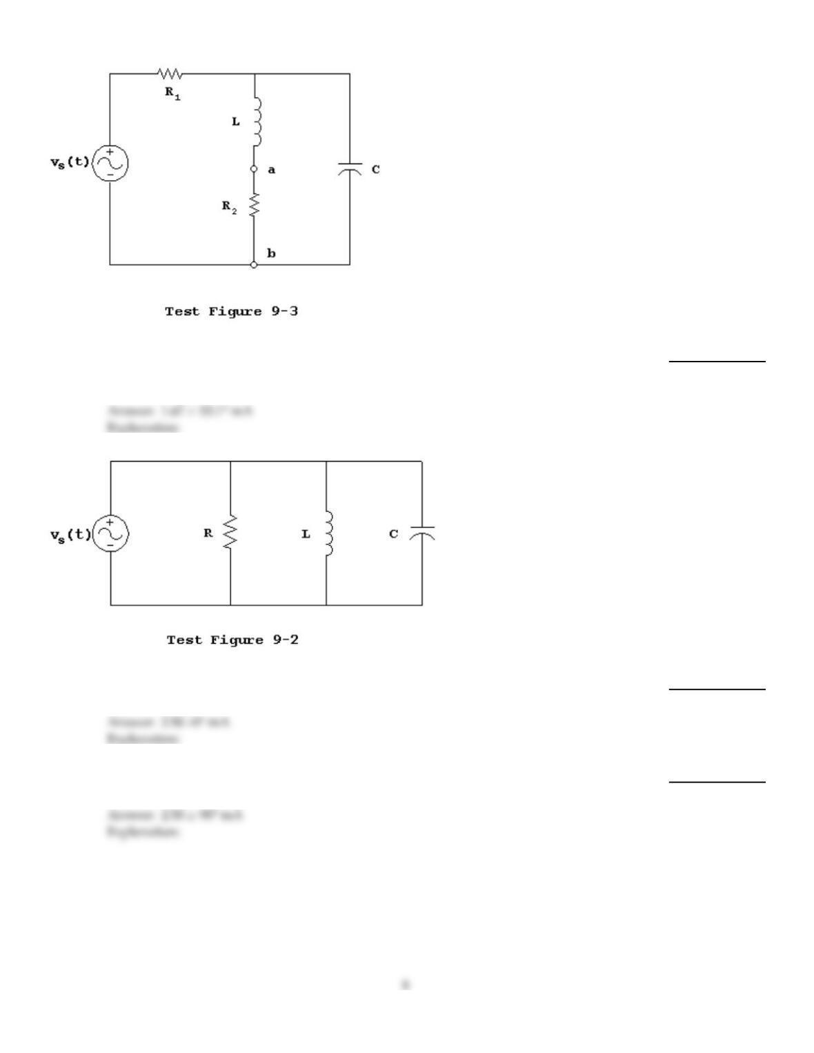
Assume that vs(t) = 35.355sin(1000t), R = 10 k, XC = 20 k,and XL = 10 k. The RMS
current through the capacitor of Test Figure 9-2 is ________.
23)
24)
Assume that vs(t) = 35.355sin(1000t), R = 10 k, XC = 20 k,and XL = 10 k. The RMS
voltage across the inductor of Test Figure 9-1 is ________.
24)
25)
Assume that vs(t) = 35.355sin(1000t), R = 10 k, XC = 20 k,and XL = 10 k. The sum of
the RMS currents through the parallel combination of the resistor and inductor of Test
Figure 9-2 is ________.
25)
26)
Assume that vs(t) = 35.355sin(1000t), R = 10 k, XC = 20 k,and XL = 10 k. The total
impedance of Test Figure 9-2 is ________.
26)
27)
Assume that vs(t) = 35.355sin(1000t), R1 = 1.0 k, R2 = 10.0 k, XC = 5.0 k,and XL = 10.0
k. The RMS current through the inductor–resistor series branch of Test Figure 9-3 is
________.
27)
28)
Assume that vs(t) = 35.355sin(1000t), R = 10 k, XC = 20 k,and XL = 10 k. The RMS
current through the resistor of Test Figure 9-2 is ________.
28)
29)
Assume that vs(t) = 35.355sin(1000t), R = 10 k, XC = 20 k,and XL = 10 k. The RMS
current through the inductor of Test Figure 9-2 is ________.
29)
30)
Assume that vs1(t) = 35.355sin(1000t), vs2(t) = 14.142sin(1000t + 45°),R1 = 1.0 k, R2 = 2.0
k, R3 = 2.0 k,and XC = 5.0 k. The total RMS voltage across R2from terminal ato
terminal bdue to both sources of Test Figure 9-4 is ________.
30)
31)
Assume that vs(t) = 35.355sin(1000t), R = 10 k, XC = 20 k,and XL = 10 k. The RMS
voltage across the resistor of Test Figure 9-1 is ________.
31)
32)
Assume that vs(t) = 35.355sin(1000t), R = 10 k, XC = 20 k,and XL = 10 k. The total
RMS current in the parallel circuit of Test Figure 9-2 is ________.
32)
33)
Assume that vs(t) = 35.355sin(1000t), R1 = 1.0 k, R2 = 10.0 k, XC = 5.0 k,and XL = 10.0
k. The RMS voltage across resistor R2of Test Figure 9-3 is ________.
33)
34)
Assume that vs(t) = 35.355sin(1000t), R = 10 k, XC = 20 k,and XL = 10 k. The total
RMS current in the series circuit of Test Figure 9-1 is ________.
34)
35)
Assume that vs(t) = 35.355sin(1000t), R = 10 k, XC = 20 k,and XL = 10 k. The sum of
the RMS voltages across the series combination of the resistor and capacitor of Test Figure
9-1 is ________.
35)
36)
Assume that vs(t) = 35.355sin(1000t), R = 10 k, XC = 20 k,and XL = 10 k. The RMS
voltage across the capacitor of Test Figure 9-1 is ________.
36)
37)
Assume that vs(t) = 35.355sin(1000t), R1 = 1.0 k, R2 = 10.0 k, XC = 5.0 k,and XL = 10.0
k. The total admittance of Test Figure 9-3 is ________.
37)
38)
Assume that vs(t) = 35.355sin(1000t), R = 10 k, XC = 20 k,and XL = 10 k. The total
admittance of Test Figure 9-2 is ________.
38)
TRUE/FALSE. Write ‘T’ if the statement is true and ‘F’ if the statement is false.
39)
Kirchhoff’s Current law (KCL) states that the sum of the phasor currents entering and leaving a
node must equal zero.
39)
40)
When using superposition, series–parallel circuit analysis cannot be used to analyze the circuit.
40)
41)
In superposition, acurrent source is deactivated by replacing it with an open to guarantee zero
current.
41)
42)
Series–parallel circuits are analyzed by applying the analysis techniques for series and parallel
circuits to series groups (branches) and parallel groups of impedances within the series–parallel
circuit.
42)
43)
Kirchhoff’s Voltage law states that the sum of the phasor voltages around any closed path, including
“through the air,” must equal zero.
43)
44)
Superposition can be used to determine voltages and currents in the circuit even if the frequency of
the sources is different.
44)
45)
Current division occurs in series circuits.
45)
46)
Superposition is the addition (with proper sign) of the corresponding phasor voltages and currents
due to each source in the circuit.
46)
47)
The total impedance in aseries circuit is the complex product of the individual impedances.
47)
48)
Admittance is one over the impedance.
48)
49)
The current divider rule (CDR) is adirect expression that current division occurs in series circuits.
49)
50)
The current can be different through each element in aseries circuit.
50)
51)
The voltage divider rule (VDR) is adirect expression of the fact that voltage division occurs in series
circuits.
51)
52)
The model of apractical AC current source is an ideal current source in parallel with an internal
impedance.
52)
53)
In superposition, a voltage source is deactivated by placing ashort across the source to guarantee
zero voltage. This is especially true in the laboratory.
53)
54)
Admittance can only be used in parallel circuits.
54)
55)
Current division occurs in series circuits.
55)
56)
The total admittance of aparallel circuit is the sum of the individual admittances.
56)
57)
The model of apractical AC voltage source is an ideal voltage source in parallel with an internal
impedance.
57)
58)
The voltage is the same throughout an AC parallel circuit.
58)
Answer Key
Testname: C9
Answer Key
Testname: C9
16