Exam
Name___________________________________
MULTIPLE CHOICE. Choose the one alternative that best completes the statement or answers the question.
1)
Which of the following statements is true?
1)
A)
Only asynchronous events need a control clock.
B)
Asynchronous events are controlled by a clock.
C)
Asynchronous events occur independently of the circuit clock.
D)
Synchronous events do not need a clock to control them.
2)
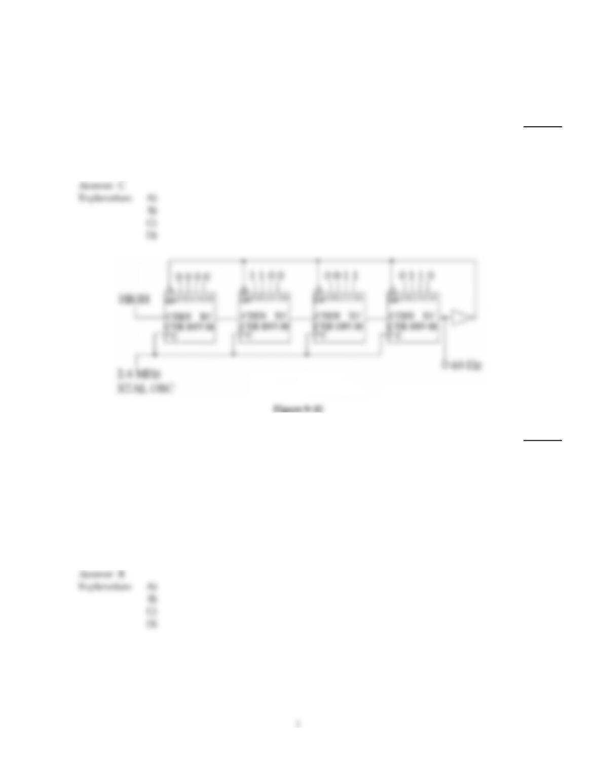
Refer to Figure 9–12. The circuit is used to derive a 60 Hz reference for a digital clock. After running
for 24 hours the clock appears to be running 2 minutes and 18 seconds slow. What appears to be
wrong with the circuit?
2)
A)
The XTAL OSC is probably cooling off too much at night and consequently slowing down;
the XTAL OSC should be temperature compensated.
B)
The modulus of the counter has increased, causing a drop in the output frequency of the
counter.
C)
The modulus of the counter has decreased, causing the counter to produce a lower output
reference signal for the clock.
D)
The error is very small and is to be expected of a circuit of this type; the clock should be
regularly reset.
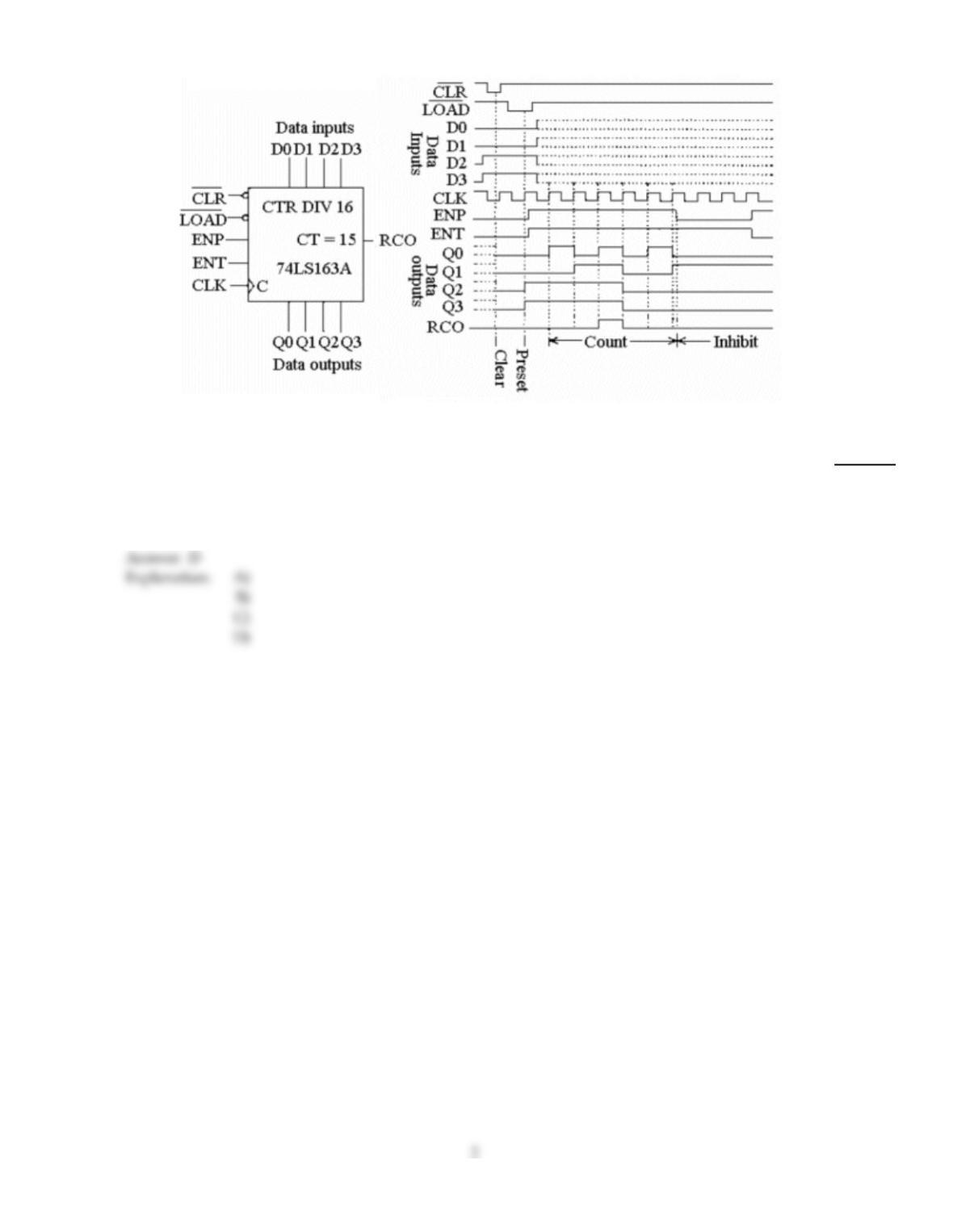
Figure 9–4
3)
What is the meaning of the label ‘CTR DIV 16′ on the 74LS163A diagram shown in Figure 9–4?
3)
A)
The circuit is a 16–bit, four–state counter.
B)
The circuit is a control device with 16 outputs.
C)
The circuit is a hexadecimal converter.
D)
The circuit is a four–bit, 16–state counter.
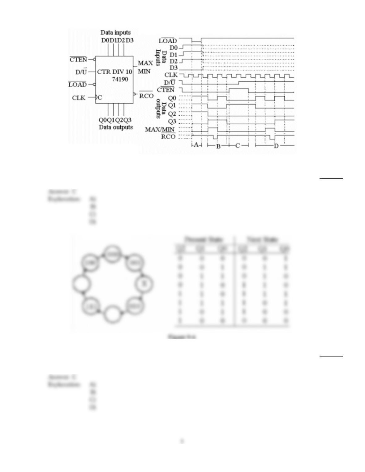
Figure 9–5
4)
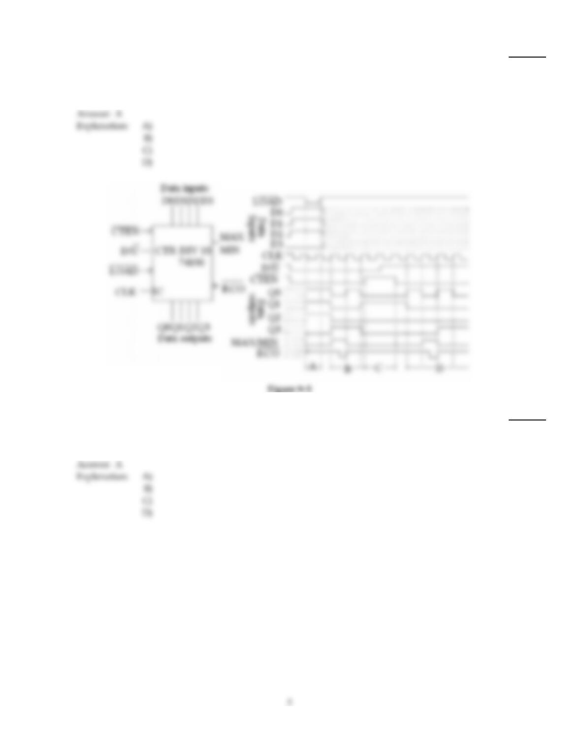
During period D on the timing diagram in Figure 9–5, the decimal count sequence is ________.
4)
A)
0, 1, 9, 8
B)
7, 8, 9, 1
C)
1, 0, 9, 8
D)
8, 9, 0, 1
5)
The table shown in Figure 9–6 is called a ________.
5)
A)
sequential truth table
B)
state diagram
C)
next–state table
D)
present state table
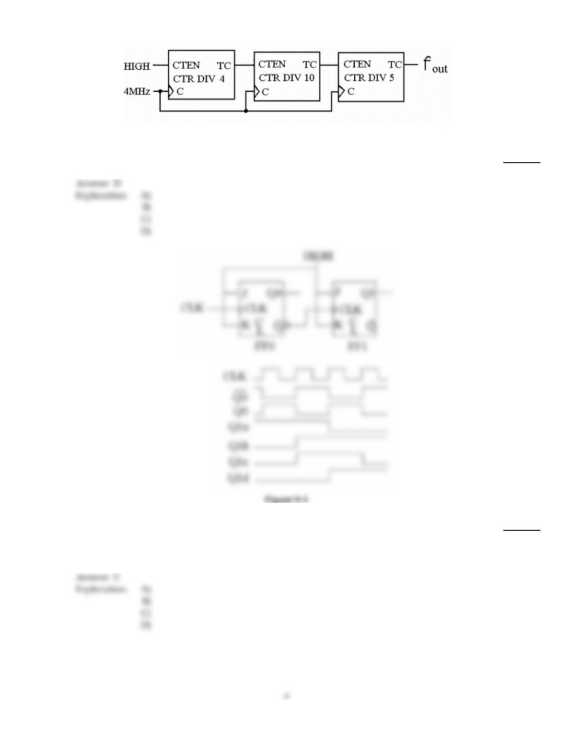
Figure 9–9
6)
What is the output frequency of the counter in Figure 9–9?
6)
A)
210.5 kHz
B)
4 MHz
C)
800 Hz
D)
20 kHz
7)
The counter shown in Figure 9–1 is a(n) ________ counter, and the correct output waveform for Q1
is ________.
7)
A)
synchronous, Q1a
B)
asynchronous, Q1b
C)
asynchronous, Q1c
D)
synchronous, Q1d
8)
Modulus refers to ________.
8)
A)
the maximum number of states in a counter sequence
B)
a method used to fabricate decade counter units
C)
the modulus of elasticity, or the ability of a circuit to be stretched from one mode to another
D)
an input on a counter that is used to set the counter state, such as UP/DOWN
9)
What function does the counter shown in Figure 9–5 perform during period A on the timing
diagram?
9)
A)
Loading
B)
Counting down
C)
Inhibited
D)
Counting up
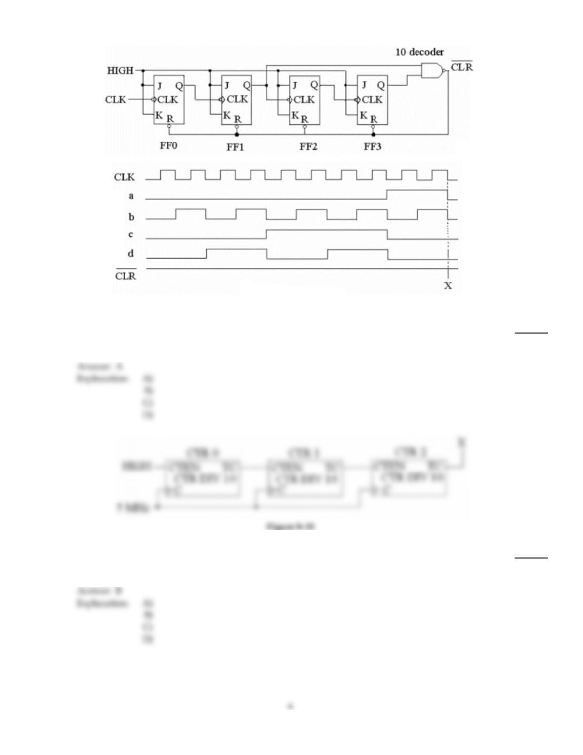
Figure 9–2
10)
The circuit in Figure 9–2 is a(n) ________.
10)
A)
four–bit asynchronous binary counter
B)
two–bit asynchronous binary counter
C)
three–bit synchronous binary counter
D)
eight–bit asynchronous binary flip–flop
11)
Refer to Figure 9–11. The TC output of CTR0 shorts to ground; what will be the output frequency at
‘X’?
11)
A)
5 kHz
B)
500 kHz
C)
0 Hz
D)
50 kHz
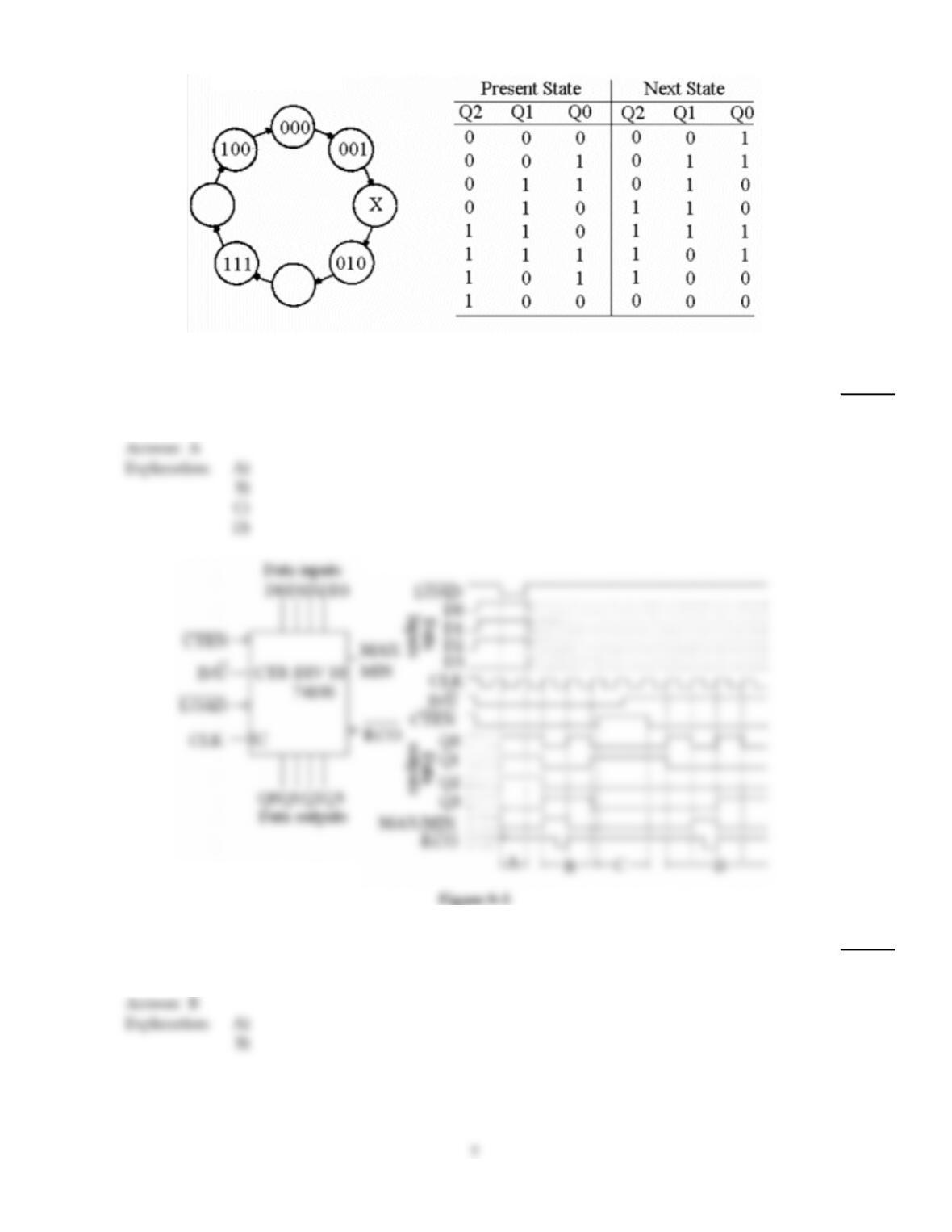
Figure 9–6
12)
The illustration shown in Figure 9–6 is referred to as a ________.
12)
A)
state diagram
B)
cyclic state chart
C)
sequential diagram
D)
clock diagram
13)
The counter in Figure 9–5 is counting DOWN; when the count reaches zero, the MAX/MIN output
will go ________.
13)
A)
LOW
B)
HIGH
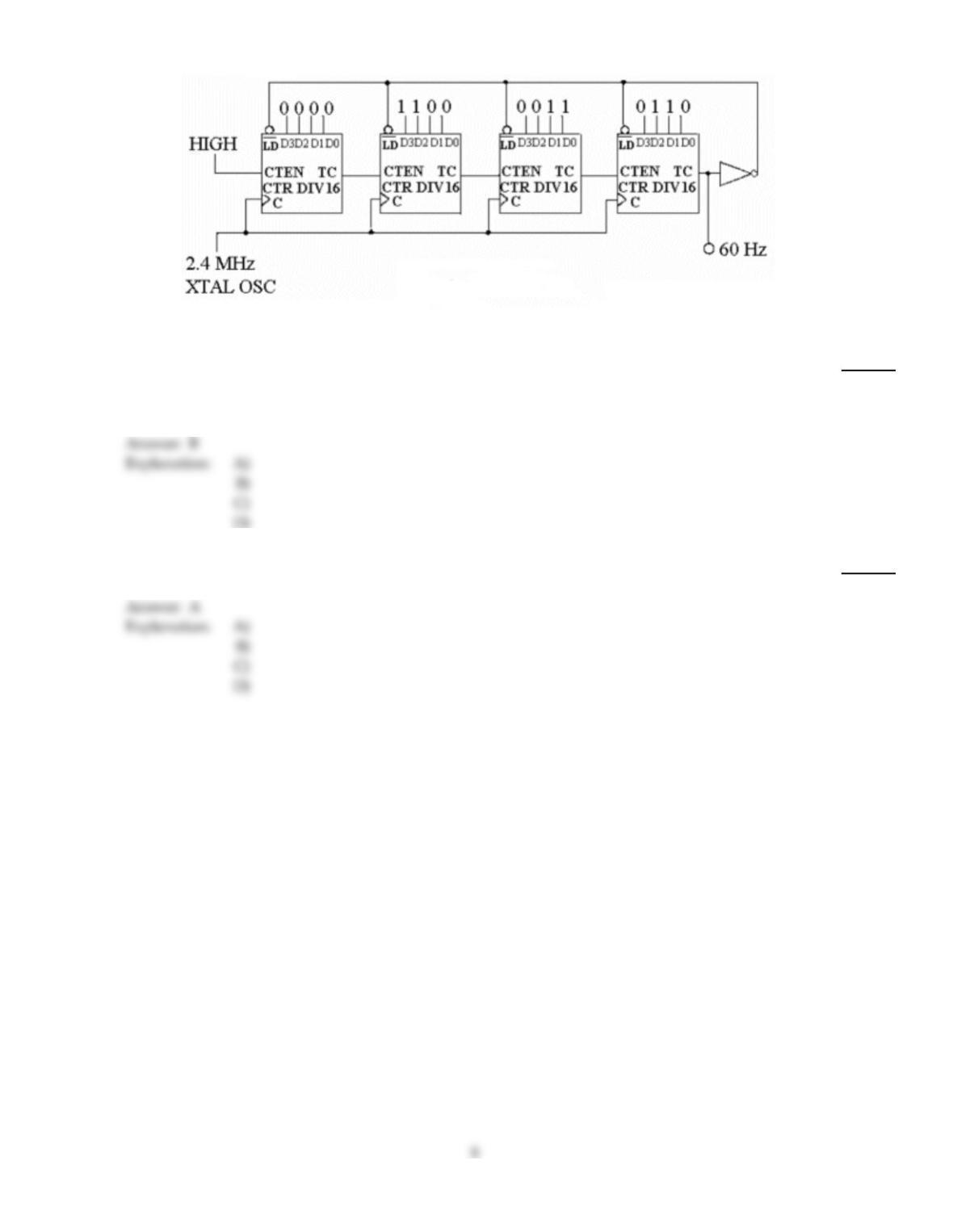
Figure 9–12
14)
One of the most common and least expensive crystals available is the 3.58 MHz crystal used in
color television sets. What hex value would have to be loaded into the counter in Figure 9–12 in
order to use the 3.58 MHz crystal to derive the 60Hz reference signal for the clock?
14)
A)
63C0
B)
E912
C)
E3C0
D)
16ED
15)
How many flip–flops are required to construct a decade counter?
15)
A)
4
B)
5
C)
8
D)
10
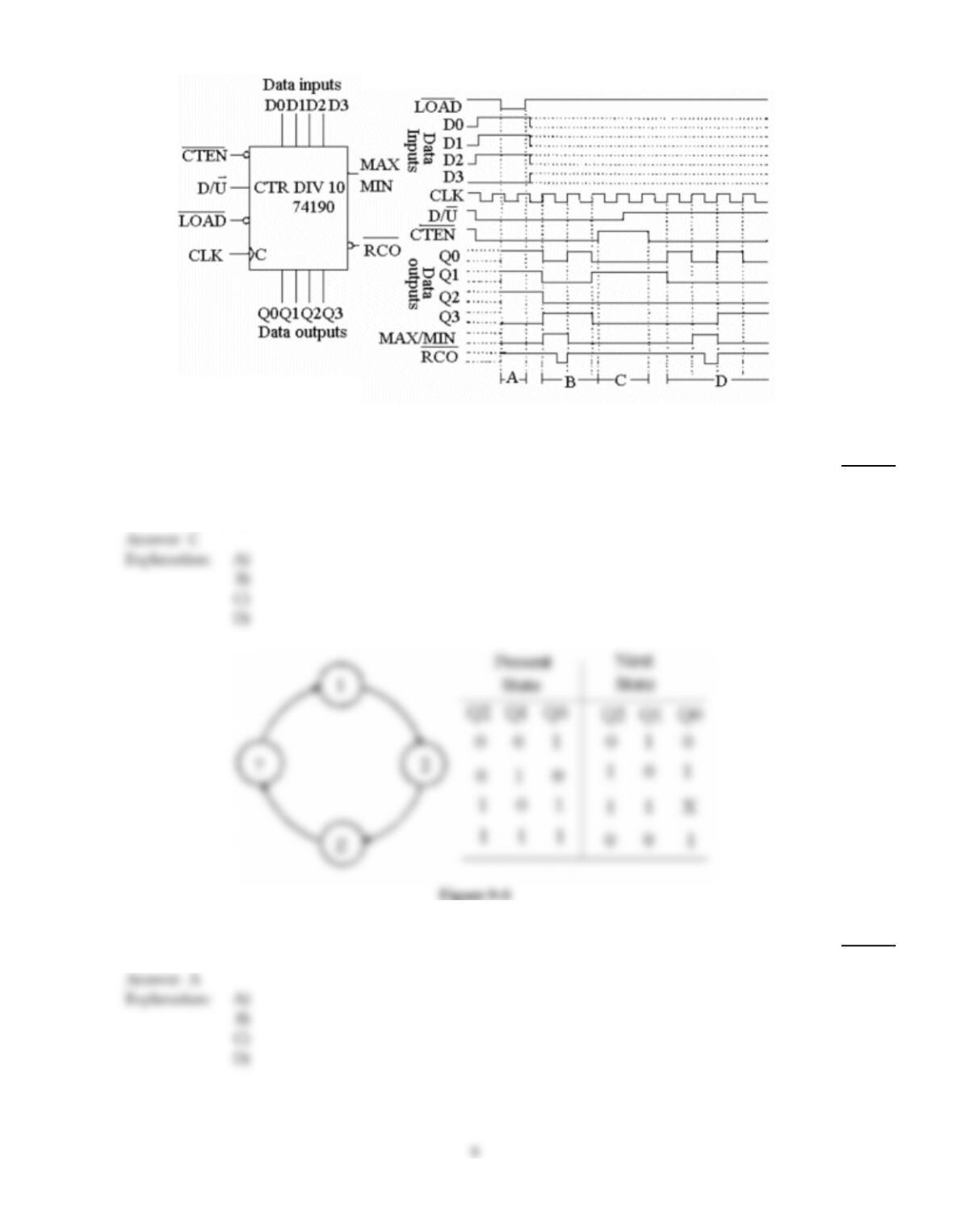
Figure 9–5
16)
What function does the counter shown in Figure 9–5 perform during period B on the timing
diagram?
16)
A)
Loading
B)
Counting down
C)
Counting up
D)
Inhibited
17)
What value does ‘Z’ represent in Figure 9–8?
17)
A)
5
B)
111
C)
4
D)
3
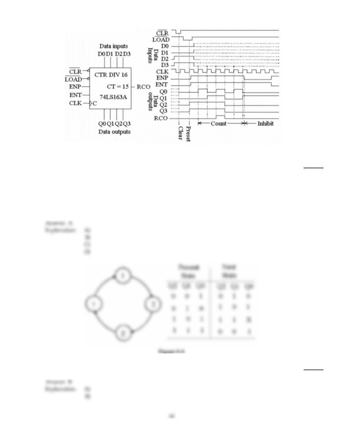
Figure 9–4
18)
Which of the following statements is correct concerning Figure 9–4?
18)
A)
Both the ENP and ENT terminals must be HIGH in order for the counter to cycle on the
leading edge of the CLK input.
B)
The active–HIGH ENT and ENP inputs must be HIGH, while the active–LOW CLR and
LOAD inputs must be LOW in order for the counter to cycle.
C)
Both the active–LOW CLR and LOAD inputs must be LOW in order for the counter to cycle.
D)
When the CLK input goes HIGH, the data on the DATA INPUT terminals is passed through
to the DATA OUTPUT terminals.
19)
Refer to Figure 9–8. What value should ‘X‘ represent in the state table?
19)
A)
0
B)
1
B
A
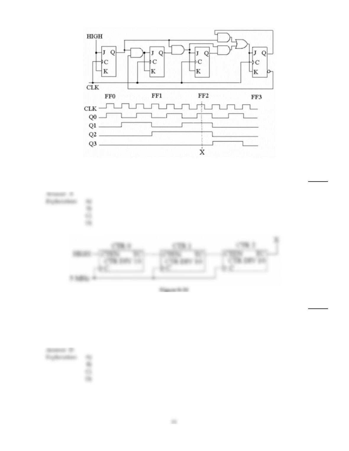
Figure 9–3
20)
Referring to the waveforms in Figure 9–3, what is the decimal count at point ‘X’?
20)
A)
7
B)
4
C)
11
D)
0110
21)
Refer to Figure 9–11. The output of the counter is checked and found to be 50 kHz. Is the counter
working correctly? If not, what could be wrong?
21)
A)
The counter is not working correctly; the TC of CTR1 is probably shorted to ground.
B)
The counter is working correctly.
C)
The counter is defective; there is probably a bad connection on the CTEN terminal of CTR0.
D)
The counter is defective; an open exists somewhere between TC of CTR0 and CTEN of CTR1.
D
A