Chapter: Chapter 31
Learning Objectives
LO 31.1.0 Solve problems related to LC oscillations.
LO 31.1.1 Sketch an LC oscillator and explain which quantities oscillate and what constitutes
one period of the oscillation.
LO 31.1.2 For an LC oscillator, sketch graphs of the potential differences across the capacitor
and the current through the inductor as functions of time, and indicate the period T on each
graph.
LO 31.1.3 Explain the analogy between a block-spring oscillator and an LC oscillator.
LO 31.1.4 For an LC oscillator, apply the relationships between the angular frequency ω (and the
related frequency f and period T) and the values of the inductance and capacitance.
LO 31.1.5 Starting with the energy of a block-spring system, explain the derivation of the
differential equation for charge q in an LC oscillator and then identify the solution for q(t).
LO 31.1.6 For an LC oscillator, calculate the charge q on the capacitor for any given time and
identify the amplitude Q of the charge oscillations.
LO 31.1.7 Starting from the equation giving the charge q(t) on the capacitor in an LC oscillator,
find the current i(t) in the inductor as a function of time.
LO 31.1.8 For an LC oscillator, calculate the current i in the inductor for any given time and
identify the amplitude I of the current oscillations.
LO 31.1.9 For an LC oscillator, apply the relationship between the charge amplitude Q, the
current amplitude I, and the angular frequency ω.
LO 31.1.10 From the expressions for the charge q and the current i in an LC oscillator, find the
magnetic field energy UB (t) and the electric field energy UE (t) and the total energy.
LO 31.1.11 For an LC oscillator, sketch graphs of the magnetic field energy UB(t), the electric
field energy UE(t), and the total energy, all as functions of time.
LO 31.1.12 Calculate the maximum values of the magnetic field energy UB and the electric field
energy UE and also calculate the total energy.
LO 31.2.0 Solve problems related to damped oscillations in an RLC circuit.
LO 31.2.1 Draw the schematic of a damped RLC circuit and explain why the oscillations are
damped.
LO 31.2.2 Starting with the expressions for the field energies and the rate of energy loss in a
damped RLC circuit, write the differential equation for the charge q on the capacitor.
LO 31.2.3 For a damped RLC circuit, apply the expression for charge q(t).
LO 31.2.4 Identify that in a damped RLC circuit, the charge amplitude and the amplitude of the
electric field energy decrease exponentially with time.
LO 31.2.5 Apply the relationship between the angular frequency ω‘ of a given damped RLC
oscillator and the angular frequency ω of the circuit if R is removed.
LO 31.2.6 For a damped RLC circuit, apply the expression for the electric field energy UE as a
function of time.
LO 31.3.0 Solve problems related to forced oscillations of three simple circuits.
LO 31.3.1 Distinguish alternating current from direct current.
LO 31.3.2 For an ac generator, write the emf as a function of time, identifying the emf amplitude
and driving angular frequency.
LO 31.3.3 For an ac generator, write the current as a function of time, identifying its amplitude
and its phase constant with respect to the emf.
LO 31.3.4 Draw a schematic diagram of a (series) RLC circuit that is driven by a generator.
LO 31.3.5 Distinguish driving angular frequency ωd from natural angular frequency ω.
LO 31.3.6 In a driven (series) RLC circuit, identify the conditions for resonance and the effect on
the current amplitude.
LO 31.3.7 For each of the three basic circuits (purely resistive load, purely capacitive load, and
purely inductive load), draw the circuit and sketch graphs and phasor diagrams for voltage v(t)
and current i(t).
LO 31.3.8 For the three basic circuits, apply equations for voltage v(t) and current i(t).
LO 31.3.9 On a phasor diagram for each of the basic circuits, identify angular speed, amplitude,
projection on the vertical axis, and rotation angle.
LO 31.3.10 For each basic circuit, identify the phase constant, interpret it in terms of the relative
orientations of the current phasor and voltage phasor and also in terms of leading and lagging.
LO 31.3.11 Apply the mnemonic “ELI positively is the ICE man.”
LO 31.3.12 For each basic circuit, apply the relationships between the voltage amplitude V and
the current amplitude I.
LO 31.3.13 Calculate capacitive reactance XC and inductive reactance XL.
LO 31.4.0 Solve problems related to the series RLC circuit.
LO 31.4.1 Draw the schematic diagram of a series RLC circuit.
LO 31.4.2 Identify the conditions for a mainly inductive circuit, a mainly capacitive circuit,
and a resonant circuit.
LO 31.4.3 For a mainly inductive circuit, a mainly capacitive circuit, and a resonant circuit,
sketch graphs for voltage v(t) and current i(t) and sketch phasor diagrams, indicating leading,
lagging, or resonance.
LO 31.4.4 Calculate impedance Z.
LO 31.4.5 Apply the relationship between current amplitude I, impedance Z, and emf
amplitude ℰm.
LO 31.4.6 Apply the relationships between phase constant φ and voltage amplitudes VL and VC,
and also between phase constant φ, resistance R, and reactances XL and XC .
LO 31.4.7 Identify the values of the phase constant φ corresponding to a mainly inductive circuit,
a mainly capacitive circuit, and a resonant circuit.
LO 31.4.8 For resonance, apply the relationship between the driving angular frequency ωd, the
natural angular frequency ω, the inductance L, and the capacitance C.
LO 31.4.9 Sketch a graph of current amplitude versus the ratio ωd/ω, identifying the portions
corresponding to a mainly inductive circuit, a mainly capacitive circuit, and a resonant circuit
and indicating what happens to the curve for an increase in the resistance.
LO 31.5.0 Solve problems related to power in alternating-current circuits.
LO 31.5.1 For the current, voltage, and emf in an ac circuit, apply the relationship between the
rms values and the amplitudes.
LO 31.5.2 For an alternating emf connected across a capacitor, an inductor, or a resistor, sketch
graphs of the sinusoidal variation of the current and voltage and indicate the peak and rms
values.
LO 31.5.3 Apply the relationship between average power Pavg, rms current Irms, and resistance R.
LO 31.5.4 In a driven RLC circuit, calculate the power of each element.
LO 31.5.5 For a driven RLC circuit in steady state, explain what happens to (a) the value of the
average stored energy with time and (b) the energy that the generator puts into the circuit.
LO 31.5.6 Apply the relationship between the power factor cos φ, the resistance R, and the
impedance Z.
LO 31.5.7 Identify what power factor is required in order to maximize the rate at which energy is
supplied to a resistive load.
LO 31.6.0 Solve problems related to transformers.
LO 31.6.1 For power transmission lines, identify why the transmission should be at low current
and high voltage.
LO 31.6.2 Identify the role of transformers at the two ends of a transmission line.
LO 31.6.3 Calculate the energy dissipation in a transmission line.
LO 31.6.4 Identify a transformer’s primary and secondary.
LO 31.6.5 Apply the relationship between the voltage and number of turns on the two sides of a
transformer.
LO 31.6.6 Distinguish between a step-down transformer and a step-up transformer.
LO 31.6.7 Apply the relationship between the current and number of turns on the two sides of
the transformer.
LO 31.6.8 Apply the relationship between the power into and out of an ideal transformer.
LO 31.6.9 Identify the equivalent resistance as seen from the primary side of a transformer.
LO 31.6.10 Apply the relationship between the equivalent resistance and the actual resistance.
LO 31.6.11 Explain the role of a transformer in impedance matching.
Multiple Choice
1. An LC circuit has an inductance of 15 mH and a capacitance of 10 F. At one instant the
charge on the capacitor is 25 C. At that instant the current is changing at the rate:
A) 0 A/s
B) 1.7 10–7 A/s
C) 5.9 10–3 A/s
D) 3.8 10–2 A/s
E) 170 A/s
2. A charged capacitor and an inductor are connected in series. At time t = 0 the current is
zero, but the capacitor is charged. If T is the period of the resulting oscillations, the next time,
after t = 0 that the voltage across the inductor is a maximum is:
A) T/4
B) T/2
C) T
D) 3T/2
E) 2T
3. A charged capacitor and an inductor are connected in series. At time t = 0 the current is
zero, but the capacitor is charged. If T is the period of the resulting oscillations, the next time,
after t = 0 that the energy stored in the magnetic field of the inductor is a maximum is:
A) T/4
B) T/2
C) T
D) 3T/2
E) 2T
4. A charged capacitor and an inductor are connected in series. At time t = 0 the current is
zero, but the capacitor is charged. If T is the period of the resulting oscillations, the next time,
after t = 0 that the energy stored in the electric field of the capacitor is a maximum is:
A) T/4
B) T/2
C) T
D) 3T/2
E) 2T
5. The electrical analog of a spring constant k is:
A) L
B) 1/L
C) C
D) 1/C
E) R
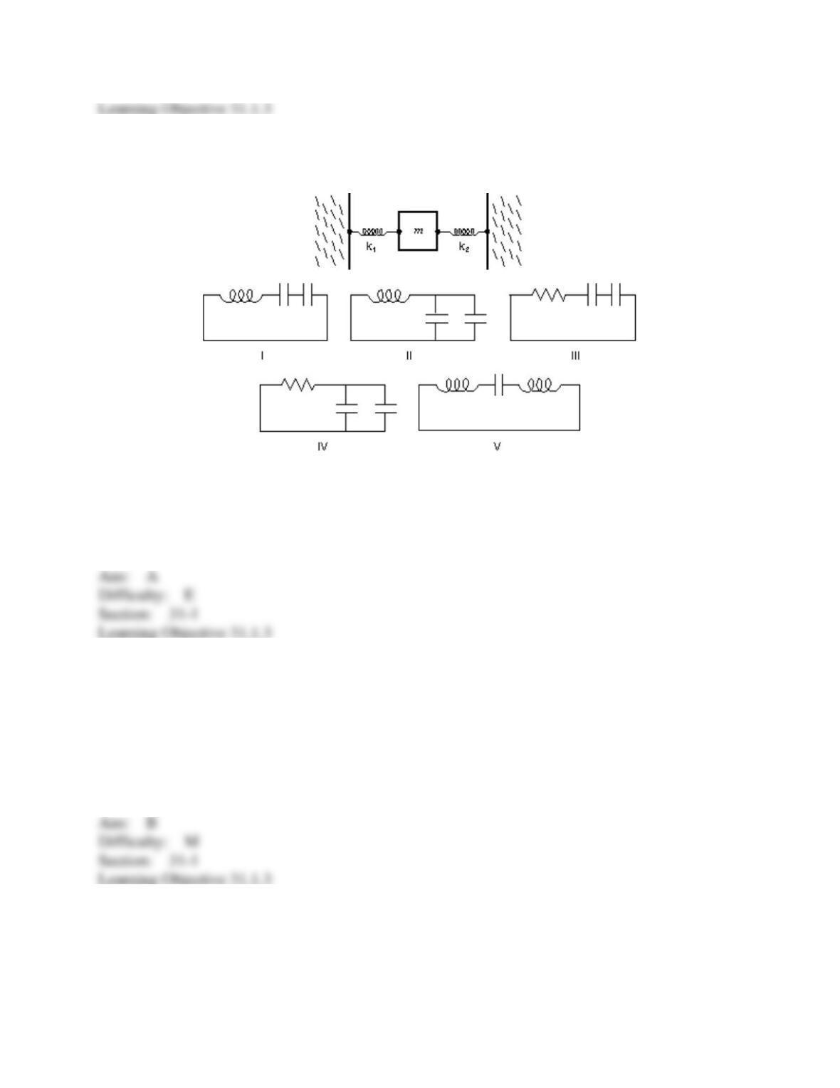
6. Consider the mechanical system consisting of two springs and a block, as shown. Which
one of the five electrical circuits (I, II, III, IV, V) is the analog of the mechanical system?
A) I
B) II
C) III
D) IV
E) V
7. A 150-g block on the end of a spring with a spring constant of 35 N/m is pulled aside 25 cm
and released from rest. In the electrical analog the initial charge on the capacitor is:
A) 0.15 C
B) 0.25 C
C) 8.8 C
D) 15 C
E) 35 C
8. A 150-g block on the end of a spring with a spring constant of 35 N/m is pulled aside 25 cm
and released from rest. In the electrical analog the maximum charge on the capacitor is 0.25 C.
The maximum current in the LC circuit is:
A) 0.025 A
B) 0.12 A
C) 3.8 A
D) 5.3 A
E) 40 A
9. Which of the following has the greatest effect in decreasing the oscillation frequency of an
LC circuit? Using instead:
A) L/2 and C/2
B) L/2 and 2C
C) 2L and C/2
D) 2L and 2C
E) none of these
10. We desire to make an LC circuit that oscillates at 100 Hz using an inductance of 2.5 H. We
also need a capacitance of:
A) 1 F
B) 1 mF
C) 1
F
D) 1 nF
E) 1 pF
11. An LC circuit consists of a 1
F capacitor and a 4 mH inductor. Its oscillation frequency is
approximately:
A) 0.025 Hz
B) 25 Hz
C) 60 Hz
D) 2500 Hz
E) 16,000 Hz
12. An LC circuit has an oscillation frequency of 105 Hz. If C = 0.1
F, then L must be about:
A) 10 mH
B) 1 mH
C) 25
H
D) 2.5
H
E) 1 pH
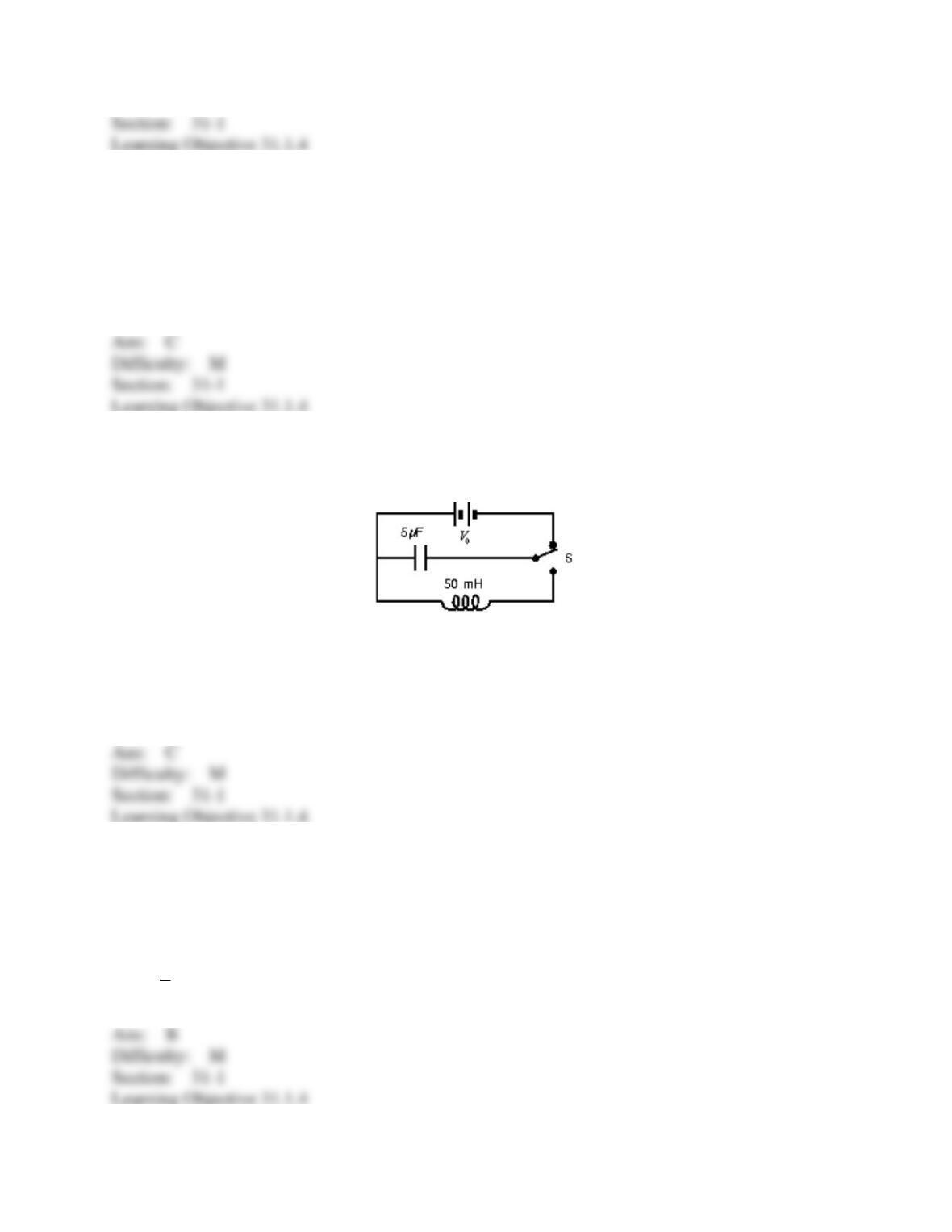
13. In the circuit shown, switch S is first pushed up to charge the capacitor. When S is then
pushed down, the current in the circuit will oscillate at a frequency of:
A) 0.010 Hz
B) 12.5 Hz
C) 320 Hz
D) 2000 Hz
E) depends on V0
14. Radio receivers are usually tuned by adjusting the capacitor of an LC circuit. If C = C1 for
a frequency of 600 kHz, then for a frequency of 1200 kHz one must adjust C to:
A) C1/2
B) C1/4
C) 2C1
D) 4C1
E) √2𝐶1
15. An LC series circuit with an inductance L and a capacitance C has an oscillation frequency
f. If we now take two of those inductors, each with inductance L, and two of the capacitors, each
with capacitance C, and wire them all in series to make a new circuit, its oscillation frequency
will be:
A) f/4
B) f/2
C) f
D) 2f
E) 4f
16. A charged capacitor and an inductor are connected in series. At time t = 0 the current is
zero, but the capacitor is charged. If T is the period of the resulting oscillations, the next time,
after t = 0 that the charge on the capacitor is a maximum is:
A) T/4
B) T/2
C) T
D) 3T/2
E) 2T
17. A charged capacitor and an inductor are connected in series. At time t = 0 the current is
zero, but the capacitor is charged. If T is the period of the resulting oscillations, the next time,
after t = 0 that the current is a maximum is:
A) T/4
B) T/2
C) T
D) 3T/2
E) 2T
18. An LC circuit has an inductance of 20 mH and a capacitance of 5.0 F. If the charge
amplitude is 40 C, what is the current amplitude?
A) 0.025 A
B) 0.13 A
C) 1.0 A
D) 7.9 A
E) 400 A
19. A capacitor in an LC oscillator has a maximum potential difference of 15 V and a
maximum energy of 360 J. At a certain instant the energy in the capacitor is 40 J. At that
instant what is the potential difference across the capacitor?
A) 0 V
B) 5 V
C) 10 V
D) 15 V
E) 20 V
20. A capacitor in an LC oscillator has a maximum potential difference of 15 V and a
maximum energy of 360 J. At a certain instant the energy in the capacitor is 40 J. At that
instant what is the emf induced in the inductor?
A) 0 V
B) 5 V
C) 10 V
D) 15 V
E) 20 V
21. In an oscillating LC circuit, the total stored energy is U. The maximum energy stored in the
capacitor during one cycle is:
A) U/2
B) 𝑈/√2
C) U
D) U/(2)
E) U/
22. In an oscillating LC circuit, the total stored energy is U and the maximum charge on the
capacitor is Q. When the charge on the capacitor is Q/2, the energy stored in the inductor is:
A) U/2
B) U/4
C) (4/3)U
D) 3U/2
E) 3U/4
23. An LC circuit has an inductance of 20 mH and a capacitance of 5.0 F. At time t = 0 the
charge on the capacitor is 3.0 C and the current is 7.0 mA. The total energy is:
A) 4.1 10–7 J
B) 4.9 10–7 J
C) 9.0 10–7 J
D) 1.4 10–6 J
E) 2.8 10–6 J
24. The total energy in an LC circuit is 5.0 10–6 J. If C = 15 F the maximum charge on the
capacitor is:
A) 0.82 C
B) 8.5 C
C) 12 C
D) 17 C
E) 24 C
25. The total energy in an LC circuit is 5.0 10–6 J. If L = 25 mH the maximum current is:
A) 10 mA
B) 14 mA
C) 20 mA
D) 28 mA
E) 40 mA
26. At time t = 0 the charge on the 50-F capacitor in an LC circuit is 15 C and there is no
current. If the inductance is 20 mH the maximum current is:
A) 15 nA
B) 15 A
C) 6.7 mA
D) 15 mA
E) 15 A
27. An LC circuit has a capacitance of 30 F and an inductance of 15 mH. At time t = 0 the
charge on the capacitor is 10 C and the current is 20 mA. The maximum charge on the
capacitor is:
A) 8.9 C
B) 10 C
C) 12 C
D) 17 C
E) 24 C
28. An LC circuit has a capacitance of 30 F and an inductance of 15 mH. At time t = 0 the
charge on the capacitor is 10 C and the current is 20 mA. The maximum current is:
A) 15 mA
B) 20 mA
C) 25 mA
D) 35 mA
E) 42 mA
29. An RLC circuit has a resistance of 200 and an inductance of 15 mH. Its oscillation
frequency is 7000 Hz. At time t = 0 the current is 25 mA and there is no charge on the capacitor.
After five complete cycles the current is:
A) 0 A
B) 1.8 10–6 A
C) 2.1 10–4 A
D) 2.3 10–3 A
E) 2.5 10–2 A
30. The rapid exponential decay in just a few cycles of the charge on the plates of capacitor in
an RLC circuit might due to:
A) a large inductance
B) a large capacitance
C) a small capacitance
D) a large resistance
E) a small resistance
31. An RLC circuit has a capacitance of 12 F, an inductance of 25 mH, and a resistance of 60
. The current oscillates with an angular frequency of:
A) 1.2 103 rad/s
B) 1.4 103 rad/s
C) 1.8 103 rad/s
D) 2.2 103 rad/s
E) 2.6 103 rad/s
32. An RLC circuit has a resistance of 200 an inductance of 15 mH, and a capacitance of 34
nF. At time t = 0 the charge on the capacitor is 25 µC and there is no current flowing. After
five complete cycles the energy stored in the capacitor is:
A) 0.64 µJ
B) 77 µJ
C) 0.49 mJ
D) 1.8 mJ
E) 9.2 mJ
33. The angular frequency of a certain RLC series circuit is
0. A source of sinusoidal emf,
with angular frequency 2
0, is inserted into the circuit. After transients die out the angular
frequency of the current oscillations is:
A)
0/2
B)
0
C) 1.5
0
D) 2
0
E) 3
0
34. The angular frequency of a certain RLC series circuit is
0. A source of sinusoidal emf,
with angular frequency
, is inserted into the circuit and
is varied while the amplitude of the
source is held constant. For which of the following values of
is the amplitude of the current
oscillations the greatest?
A)
0/5
B)
0/2
C)
0
D) 2
0
E) None of them (they all produce the same current amplitude)
35. A 35-F capacitor is connected to an ac source of emf with a frequency of 250 Hz and a
maximum emf of 20 V. If the voltage across the capacitor is zero at time t = 0, what is the
voltage at time t = 3.0 ms? Assume the phase constant is zero.
A) −20 V
B) −10 V
C) 0 V
D) 10 V
E) 20 V
36. A 45-mH inductor is connected to an ac source of emf with a frequency of 250 Hz and a
maximum emf of 20 V. If the voltage across the inductor is zero at time t = 0, what is the voltage
at time t = 2.0 ms? Assume the phase constant is zero.
A) −20 V
B) −10 V
C) 0 V
D) 10 V
E) 20 V
37. A 35-F capacitor is connected to an ac source of emf with a frequency of 400 Hz and a
maximum emf of 20 V. The maximum current is:
A) 0 A
B) 0.28 A
C) 1.8 A
D) 230 A
E) 1400 A
38. A 45-mH inductor is connected to an ac source of emf with a frequency of 400 Hz and a
maximum emf of 20 V. The maximum current is:
A) 0 A
B) 0.18 A
C) 1.1 A
D) 360 A
E) 2300 A
39. The reactance of a 35-F capacitor connected to a 400-Hz generator is:
A) 0 Ω
B) 0.014 Ω
C) 0.088 Ω
D) 11 Ω
E) 71 Ω
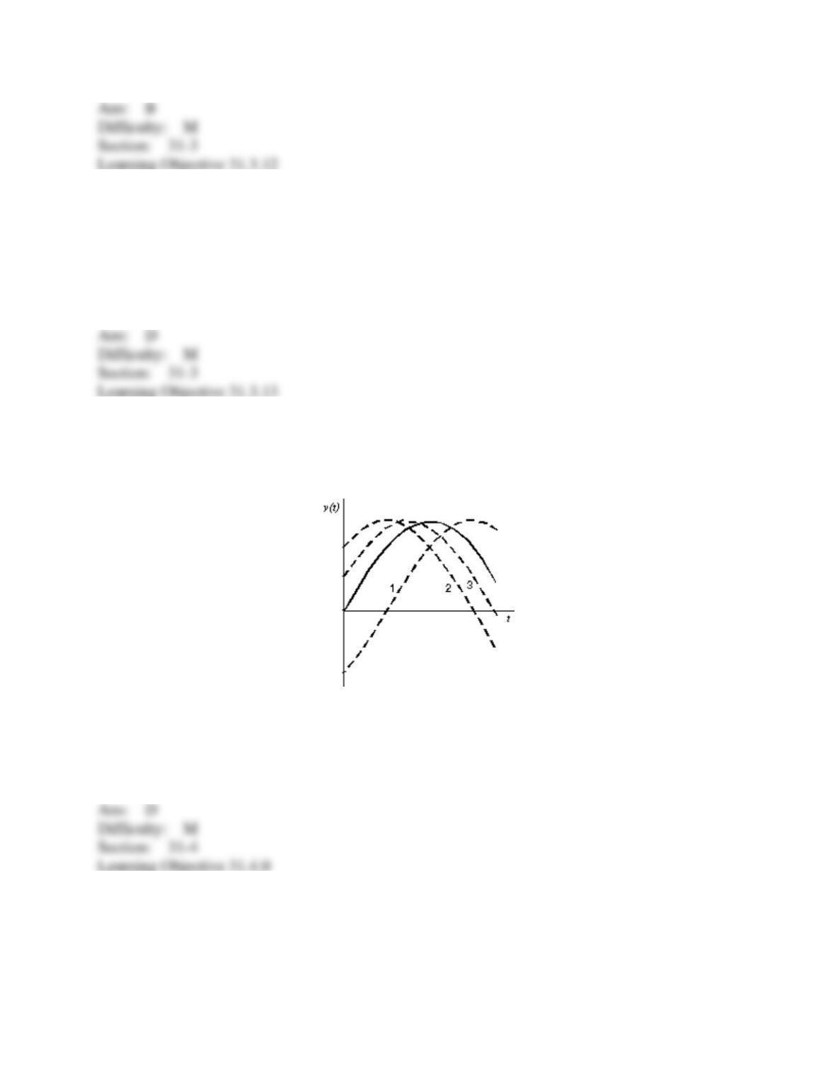
40. In the diagram, the function y(t) = ymsin(
t) is plotted as a solid curve. The other three
curves have the form y(t) = ymsin(
t +
), where
is between –/2 and +/2. Rank the curves
according to the value of
, from the most negative to the most positive.
A) 1, 2, 3
B) 2, 3, 1
C) 3, 2, 1
D) 1, 3, 2
E) 2, 1, 3
41. A resistor, an inductor, and a capacitor are connected in parallel to a sinusoidal source of
emf. Which of the following is true?
A) The currents in all branches are in phase.
B) The potential differences across all branches are in phase.