Chapter: Chapter 30
Learning Objectives
LO 30.1.0 Solve problems related to Faraday’s Law and Lenz’s Law.
LO 30.1.1 Identify that the amount of magnetic field piercing a surface (not skimming along the
surface) is the magnetic flux Φ through the surface.
LO 30.1.2 Identify that an area vector for a flat surface is a vector that is perpendicular to the
surface and that has a magnitude equal to the area of the surface.
LO 30.1.3 Identity that any surface can be divided into area elements (patch elements) that are
each small enough and flat enough for an area vector 𝑑𝐴
⃗ to be assigned to it, with the vector
perpendicular to the element and having a magnitude equal to the area of the element.
LO 30.1.4 Calculate the magnetic flux Φ through a surface by integrating the dot product of the
magnetic field vector 𝐵
⃗
⃗
and the area vector 𝑑𝐴
⃗ (for patch elements) over the surface, in
magnitude-angle notation and unit-vector notation.
LO 30.1.5 Identify that a current is induced in a conducting loop while the number of magnetic
field lines intercepted by the loop is changing.
LO 30.1.6 Identify that an induced current in a conducting loop is driven by an induced emf.
LO 30.1.7 Apply Faraday’s law, which is the relationship between an induced emf in a
conducting loop and the rate at which magnetic flux through the loop changes.
LO 30.1.8 Extend Faraday’s law from a loop to a coil with multiple loops
LO 30.1.9 Identify the three general ways in which the magnetic flux through a coil can change.
LO 30.1.10 Use a right-hand rule for Lenz’s law to determine the direction of induced emf and
induced current in a conducting loop.
LO 30.1.11 Identify that when a magnetic flux through a loop changes, the induced current in the
loop sets up a magnetic field to oppose that change.
LO 30.1.12 If an emf is induced in a conducting loop containing a battery, determine the net emf
and calculate the corresponding current in the loop.
LO 30.2.0 Solve problems related to induction and energy transfers.
LO 30.2.1 For a conducting loop pulled into or out of a magnetic field, calculate the rate at
which energy is transferred to thermal energy.
LO 30.2.2 Apply the relationship between an induced current and the rate at which it produces
thermal energy.
LO 30.2.3 Describe eddy currents.
LO 30.3.0 Solve problems related to induced electric fields.
LO 30.3.1 Identify that a changing magnetic field induces an electric field, regardless of whether
there is a conducting loop.
LO 30.3.2 Apply Faraday’s law to relate the electric field 𝐸
⃗
⃗
induced along a closed path
(whether it has conducting material or not) to the rate of change dΦ/dt of the magnetic flux
encircled by the path.
LO 30.3.3 Identify that an electric potential cannot be associated with an induced electric field.
LO 30.4.0 Solve problems related to inductors and inductance.
LO 30.4.1 Identify an inductor.
LO 30.4.2 For an inductor, apply the relationship between inductance L, total flux NΦ, and
current i.
LO 30.4.3 For a solenoid, apply the relationship between the inductance per unit length L/ℓ, the
area A of each turn, and the number of turns per unit length n.
LO 30.5.0 Solve problems related to self-induction.
LO 30.5.1 Identify that an induced emf appears in a coil when the current through the coil is
changing and that this emf is included in a loop equation for the circuit.
LO 30.5.2 Apply the relationship between the induced emf in a coil, the coil’s inductance L, and
the rate di/dt at which the current is changing.
LO 30.5.3 When an emf is induced in a coil by a changing current, determine the direction of the
emf by using Lenz’s law to show that the emf always opposes the change in the current,
attempting to maintain the initial current.
LO 30.6.0 Solve problems related to RL circuits.
LO 30.6.1 Sketch a schematic diagram of an RL circuit in which the current is rising.
LO 30.6.2 Write a loop equation (a differential equation) for an RL circuit in which the current is
rising.
LO 30.6.3 For an RL circuit in which the current is rising, apply the equation i(t) for the current
as a function of time.
LO 30.6.4 For an RL circuit in which the current is rising, find equations for the potential
difference V across the resistor, the rate di/dt at which the current changes, and the emf of the
inductor, as functions of time.
LO 30.6.5 Calculate an inductive time constant τL.
LO 30.6.6 Sketch a schematic diagram of an RL circuit in which the current is decaying.
LO 30.6.7 Write a loop equation (a differential equation) for an RL circuit in which the current is
decaying.
LO 30.6.8 For an RL circuit in which the current is decaying, apply the equation i(t) for the
current as a function of time.
LO 30.6.9 From an equation for decaying current in an RL circuit, find equations for the
potential difference V across the resistor, the rate di/dt at which current is changing, and the emf
of the inductor, as functions of time.
LO 30.6.10 For an RL circuit, identify the current through the inductor and the emf across it just
as current in the circuit begins to change and a long time later when equilibrium is reached.
LO 30.7.0 Solve problems related to energy stored in a magnetic field.
LO 30.7.1 Describe the derivation of the equation for the magnetic field energy of an inductor in
an RL circuit.
LO 30.7.2 For an inductor, apply the relationship between that magnetic field energy U, the
inductance L, and the current i.
LO 30.8.0 Solve problems related to energy density of a magnetic field.
LO 30.8.1 Identify that energy is associated with any magnetic field.
LO 30.8.2 Apply the relationship between energy density u of a magnetic field and the magnetic
field magnitude B.
LO 30.9.0 Solve problems related to mutual induction.
LO 30.9.1 Describe the mutual induction of two coils and sketch the arrangement.
LO 30.9.2 Calculate the mutual inductance of one coil with respect to a second coil (or some
second current that is changing).
LO 30.9.3 Calculate the emf induced in one coil by a second coil in terms of the mutual
inductance and the rate of change of the current in the second coil.
Multiple Choice
1. The emf that appears in Faraday’s law is:
A) around a conducting circuit
B) around the boundary of the surface used to compute the magnetic flux
C) throughout the surface used to compute the magnetic flux
D) perpendicular to the surface used to compute the magnetic flux
E) none of the above
2. 1 weber is the same as:
A) 1 V/s
B) 1 T/s
C) 1 T/m
D) 1 Tm2
E) 1 T/m2
3. 1 weber is the same as:
A) 1 Vs
B) 1 Ts
C) 1 T/m
D) 1 V/s
E) 1 T/m2
4. The units of motional emf are:
A) volt/second
B) voltmeter/second
C) volt/tesla
D) tesla/second
E) teslameter2/second
5. The magnetic flux ΦB through a surface:
A) is the amount of magnetic field piercing the surface.
B) is the magnetic field multiplied by the area.
C) does not depend on the area involved.
D) is the line integral of the magnetic field around the edge of the surface.
E) is the amount of magnetic field skimming along the surface.
6. The normal to a certain 1.0 m2 area makes an angle of 60 with a uniform magnetic field.
The magnetic flux through this area is the same as the flux through a second area that is
perpendicular to the field if the second area is:
A) 0.50 m2
B) 0.87 m2
C) 1.0 m2
D) 1.2 m2
E) 2.0 m2
7. Suppose this page is perpendicular to a uniform magnetic field and the magnetic flux
through it is 5.0 Wb. If the page is turned by 30 around an edge the flux through it will be:
A) 2.5 Wb
B) 4.3 Wb
C) 5.0 Wb
D) 5.8 Wb
E) 10 Wb
8. A 2.0 T uniform magnetic field makes an angle of 30 with the z axis. The magnetic flux
through a 3.0 m2 portion of the xy plane is:
A) 2.0 Wb
B) 3.0 Wb
C) 5.2 Wb
D) 6.0 Wb
E) 12 Wb
9. A uniform magnetic field makes an angle of 30 with the z axis. If the magnetic flux through
a 1.0 m2 portion of the xy plane is 5.0 Wb then the magnetic flux through a 2.0 m2 portion of the
same plane is:
A) 2.5 Wb
B) 4.3 Wb
C) 5.0 Wb
D) 5.8 Wb
E) 10 Wb
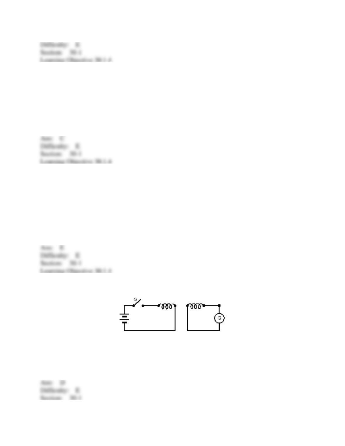
10. In the experiment shown:
A) there is a steady reading in G as long as S is closed
B) a motional emf is generated when S is closed
C) the current in the battery goes through G
D) there is a current in G just after S is opened or closed
E) since the two loops are not connected, the current in G is always zero
11. Faraday’s law states that an induced emf is proportional to:
A) the rate of change of the magnetic field
B) the rate of change of the electric field
C) the rate of change of the magnetic flux
D) the rate of change of the electric flux
E) zero
12. If the magnetic flux through a certain region is changing with time:
A) energy must be dissipated as heat
B) an electric field must not exist at the boundary
C) a current must flow around the boundary
D) an emf must exist around the boundary
E) a magnetic field must exist at the boundary
13. The emf developed in a coil X due to the current in a neighboring coil Y is proportional to
the:
A) magnetic field in X
B) rate of change of magnetic field in X
C) resistance of X
D) thickness of the wire in X
E) current in Y
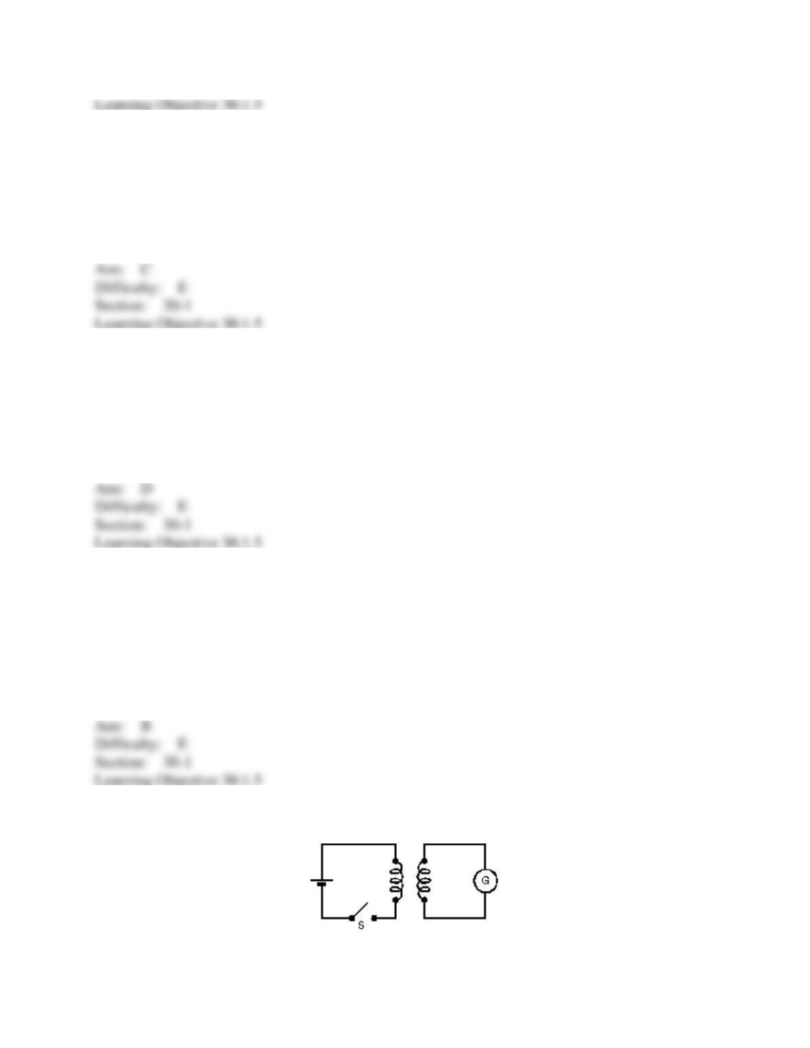
14. In the circuit shown, there will be a non-zero reading in galvanometer G:
A) only just after S is closed
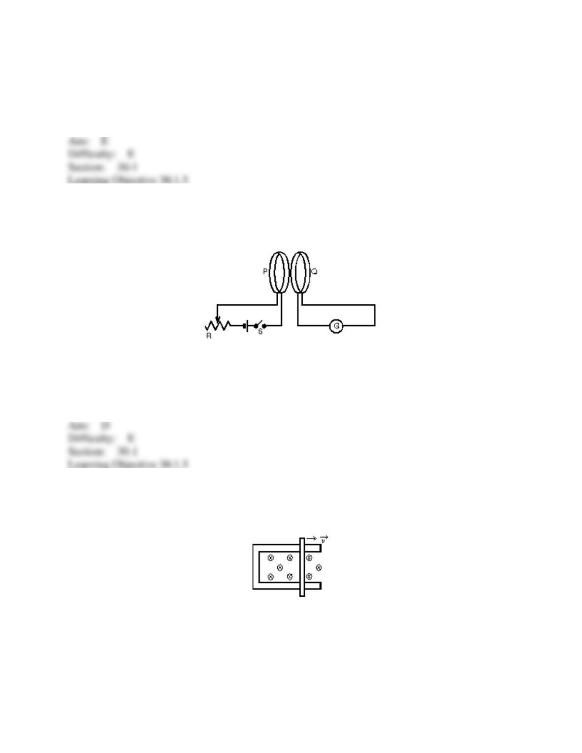
B) only just after S is opened
C) only while S is kept closed
D) never
E) only just after S is opened or closed
15. Coils P and Q each have a large number of turns of insulated wire. When switch S is
closed, the pointer of galvanometer G is deflected toward the left. Now that S is closed, to make
the pointer of G deflect toward the right one could:
A) move the slide of the rheostat R quickly to the right
B) move coil P toward coil Q
C) move coil Q toward coil P
D) open S
E) do none of the above
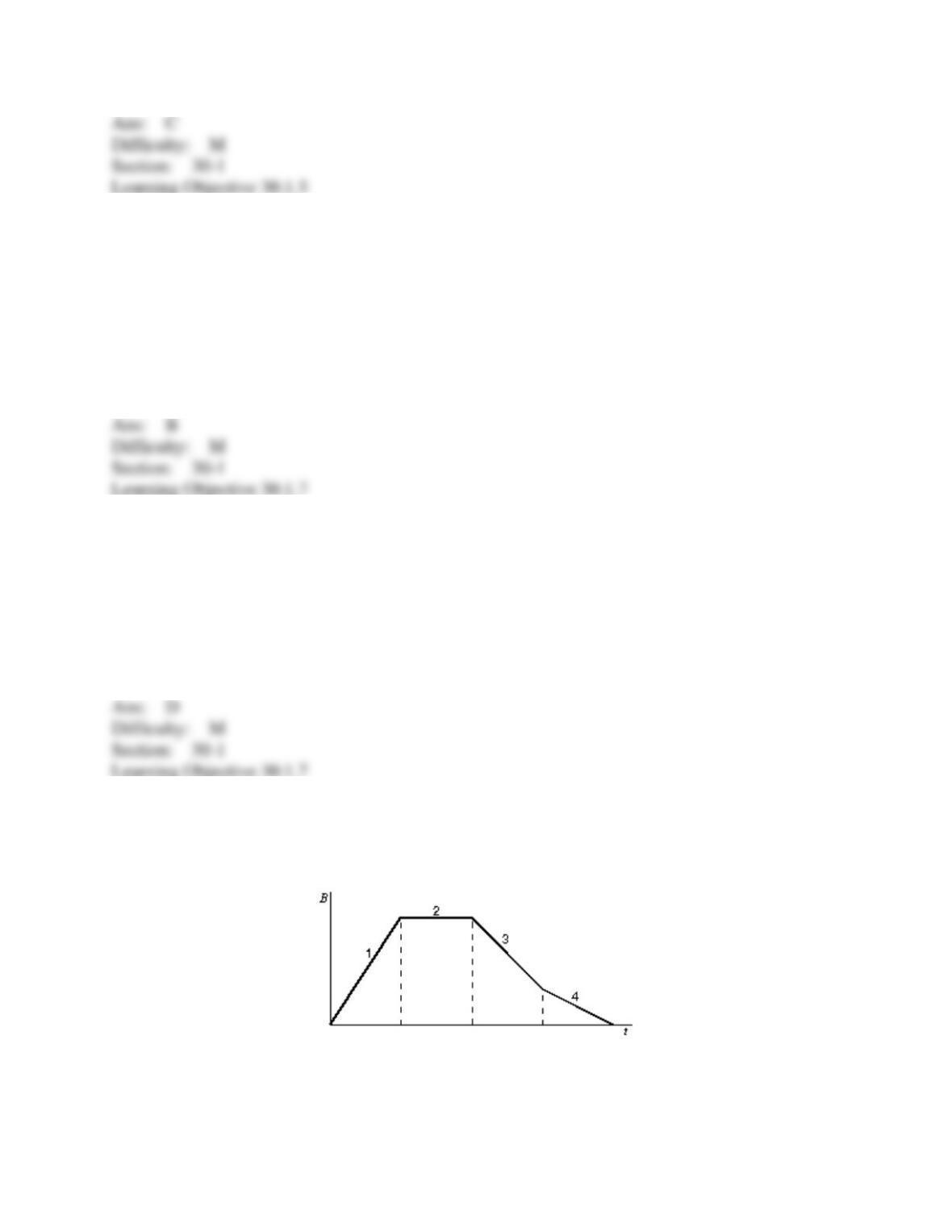
16. A rod lies across frictionless rails in a uniform magnetic field B, as shown. The rod moves
to the right with speed v. In order for the emf around the circuit to be zero, the magnitude of the
magnetic field should:
A) not change
B) increase linearly with time
C) decrease linearly with time
D) increase quadratically with time
E) decrease quadratically with time
17. A car travels northward at 75 km/h along a straight road in a region where Earth’s magnetic
field has a vertical component of 0.50 10–4 T. The emf induced between the left and right side,
separated by 1.7 m, is:
A) 0 V
B) 1.8 mV
C) 3.6 mV
D) 6.4 mV
E) 23 mV
18. A rectangular loop of wire has area A. It is placed perpendicular to a uniform magnetic
field B and then spun around one of its sides at frequency f. The maximum induced emf is:
A) BAf/2π
B) BAf
C) 2BAf
D) 2BAf
E) 4BAf
19. The graph shows the magnitude B of a uniform magnetic field that is perpendicular to the
plane of a conducting loop. Rank the four regions indicated on the graph according to the
magnitude of the emf induced in the loop, from least to greatest.
A) 1, 2, 3, 4
B) 2, 4, 3, 1
C) 4, 3, 1, 2
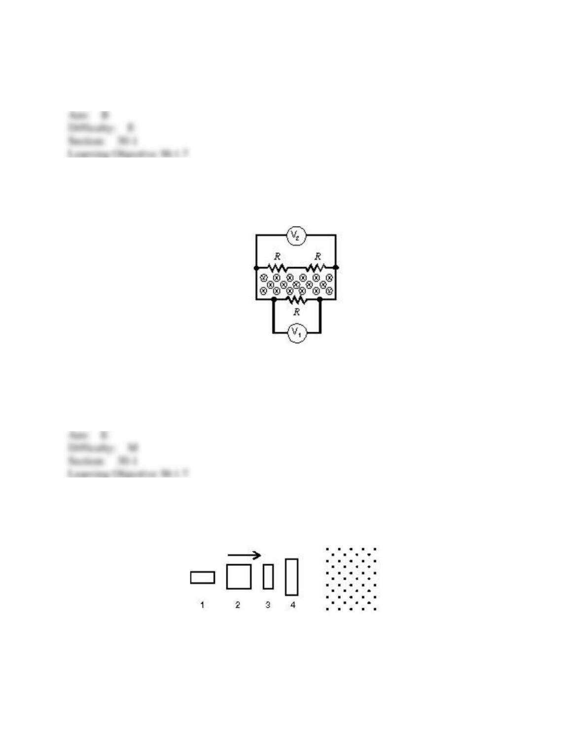
D) 1, 3, 4, 2
E) 4, 3, 2, 1
20. A changing magnetic field pierces the interior of a circuit containing three identical
resistors. Two voltmeters are connected as shown. V1 reads 1 mV across R. V2 reads the voltage
across the other two resistors, which is:
A) 0 V
B) 1/3 mV
C) 1/2 mV
D) 1 mV
E) 2 mV
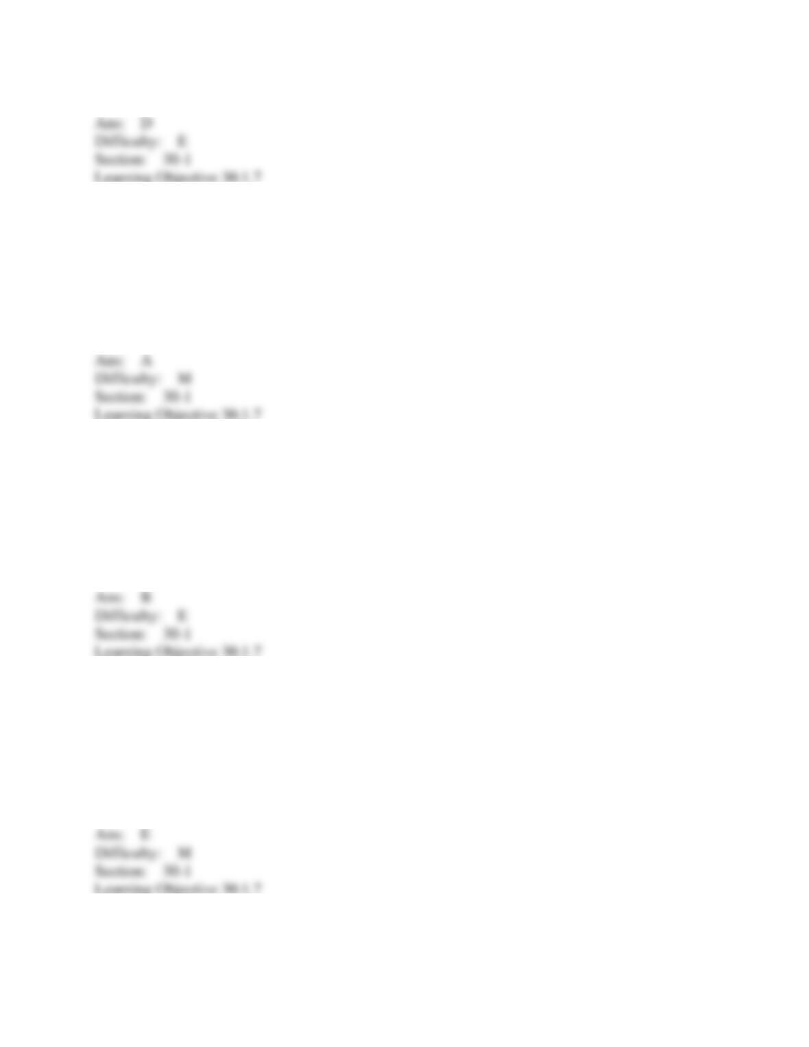
21. The four wire loops shown have edge lengths of either L, 2L, or 3L. They will move with
the same speed into a region of uniform magnetic field 𝐵
⃗
⃗
directed out of the page. Rank them
according to the maximum magnitude of the induced emf, least to greatest.
A) 1 and 2 tie, then 3 and 4 tie
B) 3 and 4 tie, then 1 and 2 tie
C) 4, then 2 and 3 tie, then 1
D) 1, then 2 and 3 tie, then 4
E) 1, 2, 3, 4
22. A rectangular loop of wire is placed perpendicular to a uniform magnetic field and then
spun around one of its sides at frequency f. The induced emf is a maximum when:
A) the flux is zero
B) the flux is a maximum
C) the flux is half its maximum value
D) the derivative of the flux with respect to time is zero
E) none of the above
23. A copper hoop is held in a vertical east-west plane in a uniform magnetic field whose field
lines run along the north-south direction. The largest induced emf is produced when the hoop is:
A) rotated about a north-south axis
B) rotated about an east-west axis
C) moved rapidly, without rotation, toward the east
D) moved rapidly, without rotation, toward the south
E) moved rapidly, without rotation, toward the northwest
24. A 10 turn conducting loop with a radius of 3.0 cm spins at 60 revolutions per second in a
magnetic field of 0.50 T. The maximum emf generated is:
A) 0.014 V
B) 0.085 V
C) 0.53 V
D) 0.85 V
E) 5.3 V
25. The diagram shows a circular loop of wire that rotates at a steady rate about a diameter O
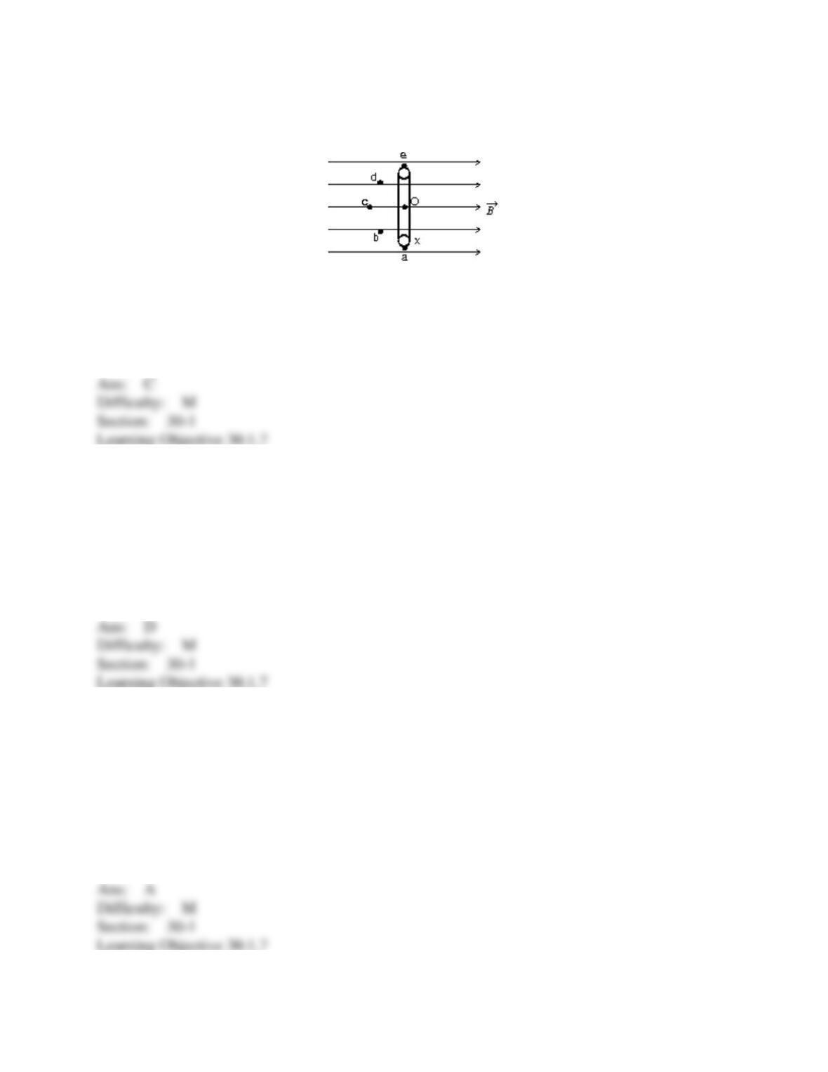
that is perpendicular to a uniform magnetic field. The maximum induced emf occurs when the
point X on the loop passes:
A) a
B) b
C) c
D) d
E) e
26. A single loop of wire with a radius of 7.5 cm rotates about a diameter in a uniform
magnetic field of 1.6 T. To produce a maximum emf of 1.0 V, it should rotate at:
A) 0 rad/s
B) 2.7 rad/s
C) 5.6 rad/s
D) 35 rad/s
E) 71 rad/s
27. A merry-go-round has an area of 300 m2 and spins at 2 rpm about a vertical axis at a place
where the Earth’s magnetic field is vertical and has a magnitude of 5 10–5 T. The emf around
the rim is:
A) 0 V
B) 0.5 mV
C) 3.1 mV
D) 15 mV
E) 190 mV
28. One hundred turns of insulated copper wire are wrapped around an iron core of
cross-sectional area 0.100 m2. The circuit is completed by connecting the coil to a 10- resistor.
As the magnetic field along the coil axis changes from 1.00 T in one direction to 1.00 T in the
other direction, the total charge that flows through the resistor is:
A) 0.01 C
B) 0.02 C
C) 0.2 C
D) 1 C
E) 2 C
29. A magnet moves inside a coil. Consider the following factors:
I.
strength of the magnet
II.
number of turns in the coil
III.
speed at which the magnet moves
Which can affect the emf induced in the coil?
A) I only
B) II only
C) III only
D) I and II only
E) I, II, III
30. A square loop of wire lies in the plane of the page. A decreasing magnetic field is
directed into the page. The induced current in the loop is:
A) counterclockwise
B) clockwise
C) zero
D) up the left edge and from right to left along the top edge
E) through the middle of the page
31. A long straight wire is in the plane of a rectangular conducting loop. The straight wire
carries a constant current i, as shown. While the wire is being moved toward the loop, the current
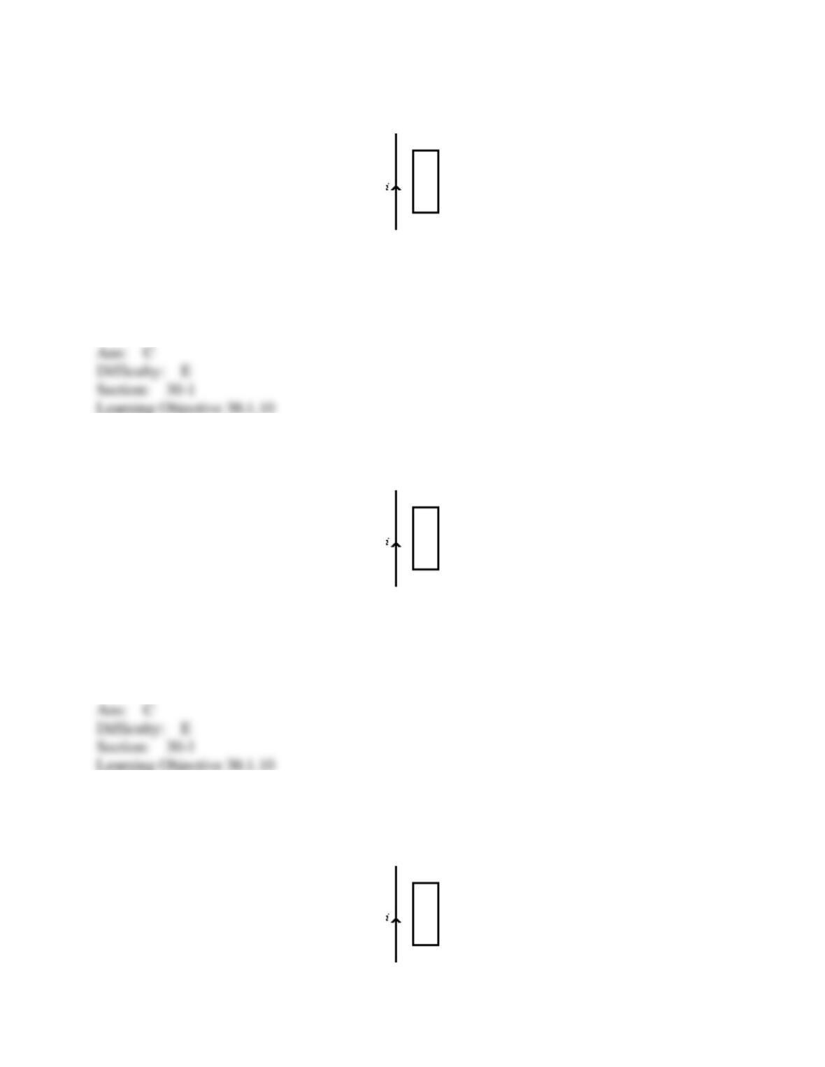
in the loop is:
A) zero
B) clockwise
C) counterclockwise
D) clockwise in the left side and counterclockwise in the right side
E) counterclockwise in the left side and clockwise in the right side
32. A long straight wire is in the plane of a rectangular conducting loop. The straight wire
carries an increasing current in the direction shown. The current in the loop is:
A) zero
B) clockwise
C) counterclockwise
D) clockwise in the left side and counterclockwise in the right side
E) counterclockwise in the left side and clockwise in the right side
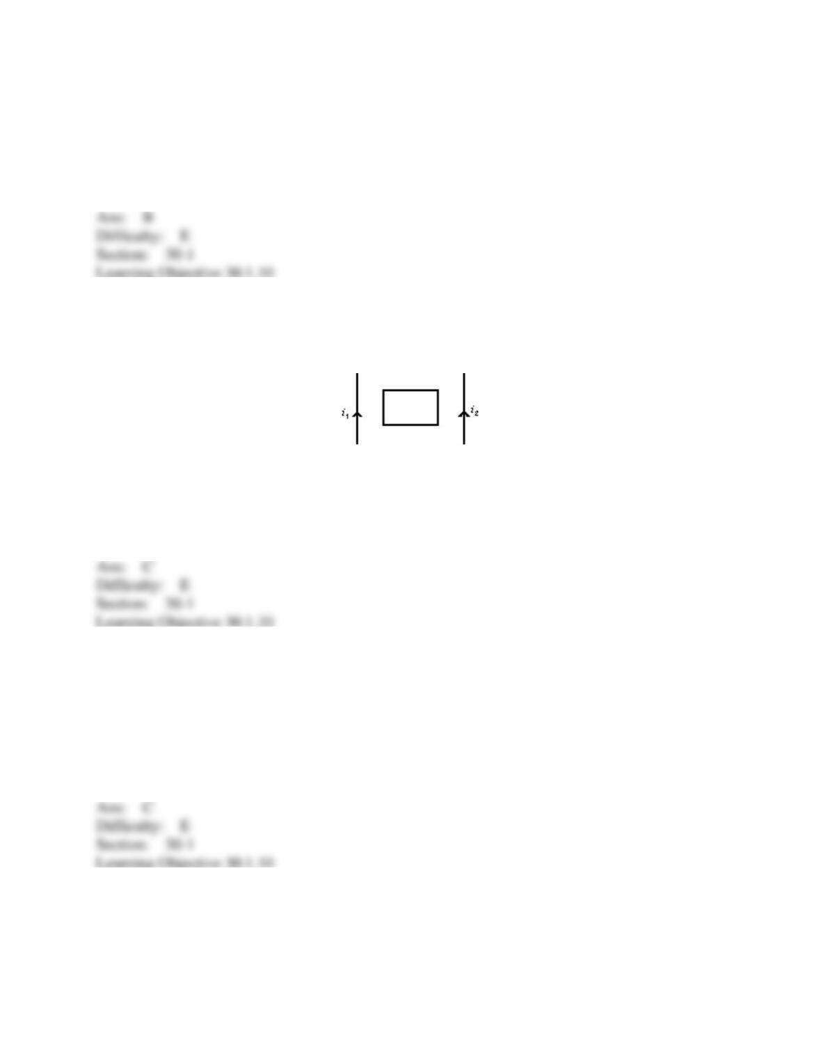
33. A long straight wire is in the plane of a rectangular conducting loop. The straight wire
initially carries a constant current i in the direction shown. While the current i is being shut off,
the current in the loop is:
A) zero
B) clockwise
C) counterclockwise
D) clockwise in the left side and counterclockwise in the right side
E) counterclockwise in the left side and clockwise in the right side
34. A rectangular loop of wire is placed midway between two long straight parallel conductors
as shown. The conductors carry currents i1 and i2 as indicated. If i1 is increasing and i2 is
constant, then the induced current in the loop is:
A) zero
B) clockwise
C) counterclockwise
D) depends on i1 – i2
E) depends on i1 + i2
35. You push a permanent magnet with its north pole away from you toward a loop of
conducting wire in front of you. Before the north pole enters the loop the current in the loop is:
A) zero
B) clockwise
C) counterclockwise
D) to your left
E) to your right
36. A vertical bar magnet is dropped through the center of a horizontal loop of wire, with its
north pole leading. At the instant when the midpoint of the magnet is in the plane of the loop, the
induced current in the loop, viewed from above, is:
A) maximum and clockwise
B) maximum and counterclockwise
C) not maximum but clockwise
D) not maximum but counterclockwise
E) essentially zero
37. A circular loop of wire rotates about a diameter in a magnetic field that is perpendicular to
the axis of rotation. Looking in the direction of the field at the loop the induced current is:
A) always clockwise
B) always counterclockwise
C) clockwise in the lower half of the loop and counterclockwise in the upper half
D) clockwise in the upper half of the loop and counterclockwise in the lower half
E) sometimes clockwise and sometimes counterclockwise
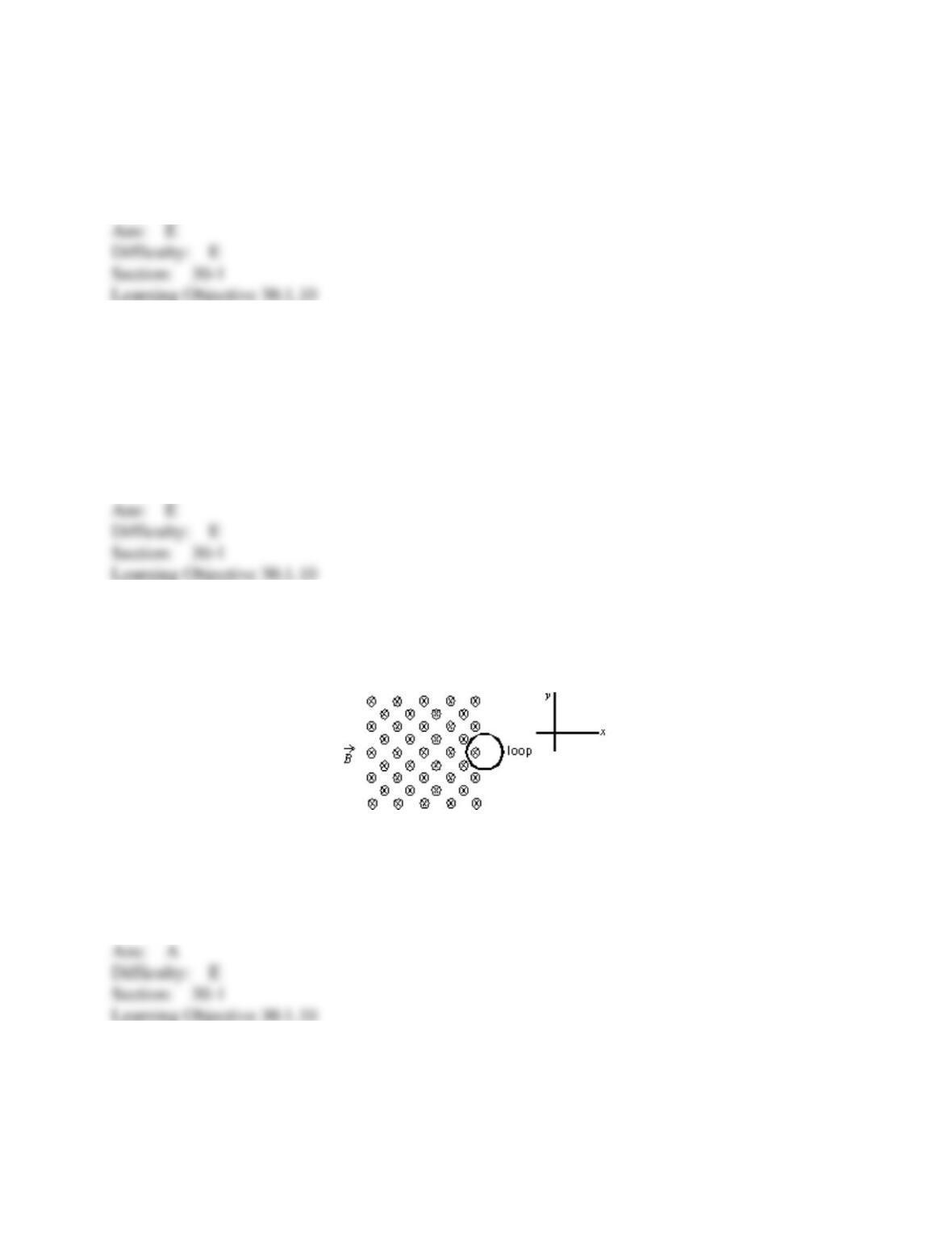
38. A circular loop of wire is positioned half in and half out of a square region of constant
uniform magnetic field directed into the page, as shown. To induce a clockwise current in this
loop:
A) move it in +x direction
B) move it in +y direction
C) move it in –x direction
D) move it in –y direction
E) increase the strength of the magnetic field
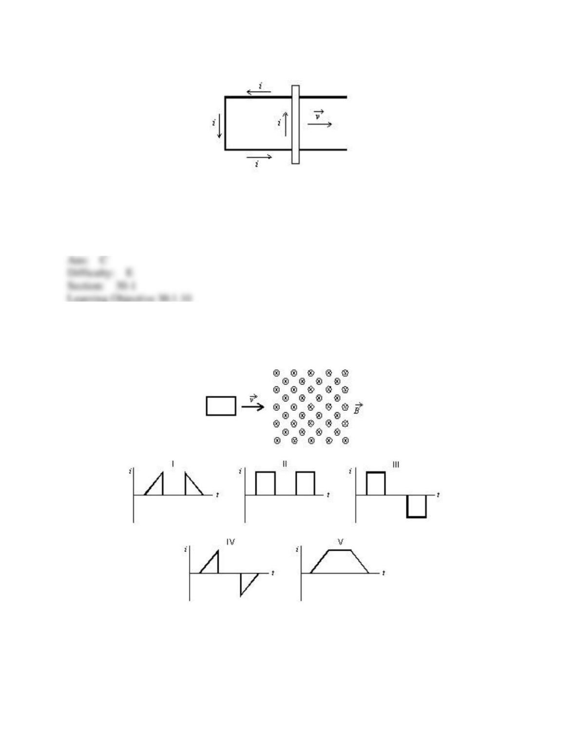
39. The figure shows a bar moving to the right on two conducting rails. To make an induced
current i in the direction indicated, a constant magnetic field between the rails should be in what
direction?
A) Right
B) Left
C) Into the page
D) Out of the page
E) Impossible, cannot be done with a constant magnetic field
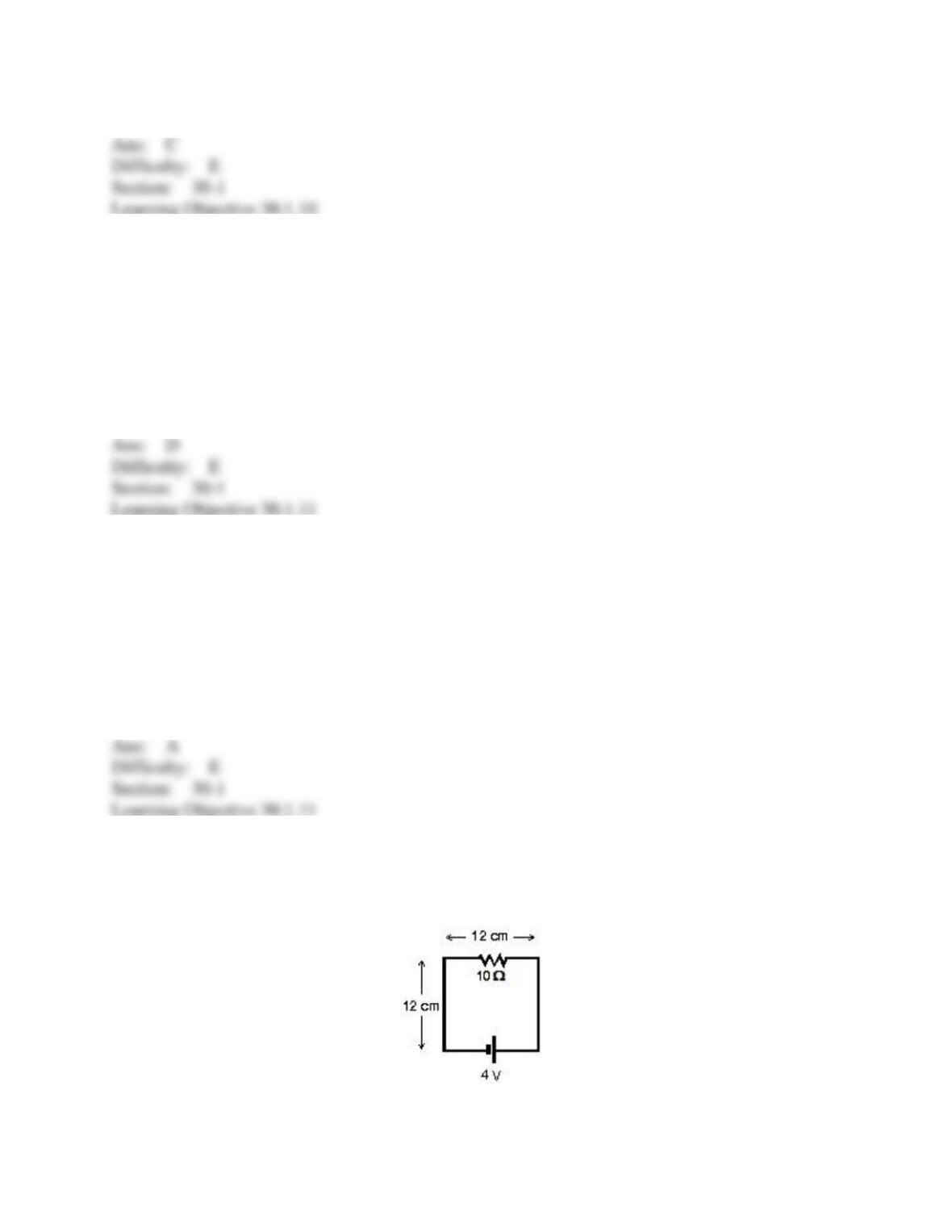
40. A square loop of wire moves with a constant speed v from a field-free region into a region
of uniform B field, as shown. Which of the five graphs correctly shows the induced current i in
the loop as a function of time t?
A) I
B) II
C) III
D) IV
E) V
41. As an externally generated magnetic field through a certain conducting loop increases in
magnitude, the field produced at points inside the loop by the current induced in the loop must
be:
A) increasing in magnitude
B) decreasing in magnitude
C) in the same direction as the applied field
D) directed opposite to the applied field
E) perpendicular to the applied field
42. At a particular instant of time the total magnetic flux through a stationary conducting loop
is less in magnitude than the flux associated with an externally applied field. This might occur
because:
A) the applied field is normal to the loop and increasing in magnitude
B) the applied field is normal to the loop and decreasing in magnitude
C) the applied field is parallel to the plane of the loop and increasing in magnitude
D) the applied field is parallel to the plane of the loop and decreasing in magnitude
E) the applied field is tangent to the loop
43. The circuit shown is in a uniform magnetic field that is into the page. The current in the
circuit is 0.20 A. At what rate is the magnitude of the magnetic field changing? Is it increasing
or decreasing?
A) 0 T/s