B) 140 T/s, decreasing
C) 140 T/s, increasing
D) 420 T/s, decreasing
E) 420 T/s, increasing
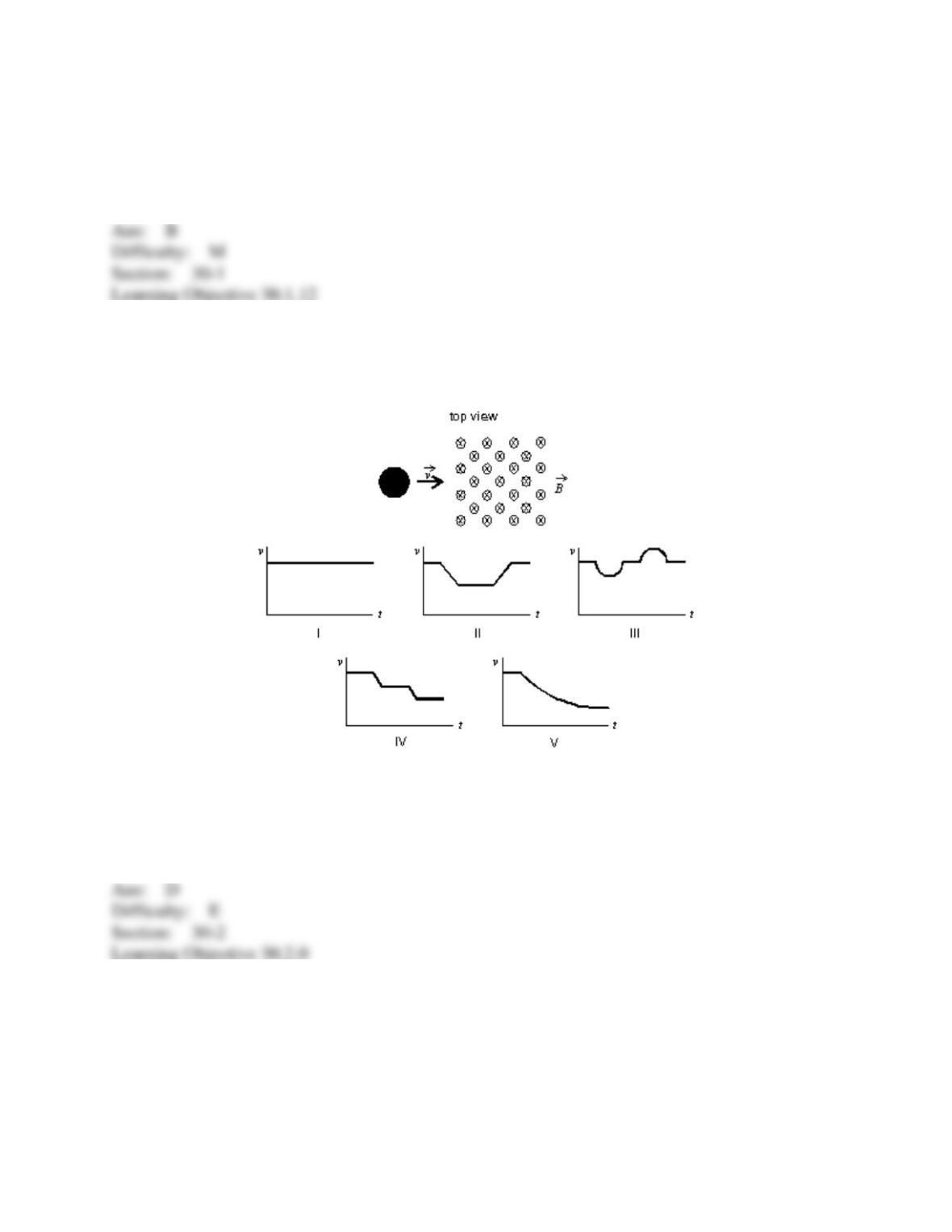
44. A copper penny slides on a horizontal frictionless table. There is a square region of
constant uniform magnetic field perpendicular to the table, as shown. Which graph correctly
shows the speed v of the penny as a function of time t?
A) I
B) II
C) III
D) IV
E) V
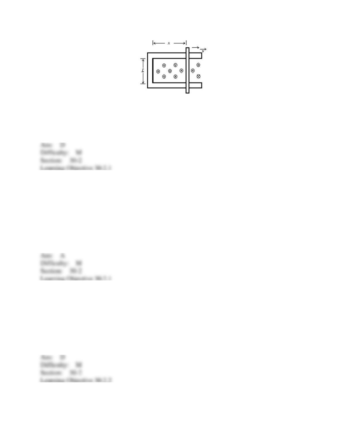
45. A rod with resistance R lies across frictionless conducting rails in a constant uniform
magnetic field B, as shown. Assume the rails have negligible resistance. The magnitude of the
force that must be applied by a person to pull the rod to the right at constant speed v is:
A) 0
B) BLv
C) BLv/R
D) B2L2v/R
E) B2Lxv/R
46. A rod of length L and electrical resistance R moves through a constant uniform magnetic
field 𝐵
⃗
⃗
; both the magnetic field and the direction of motion are parallel to the rod. The force that
must be applied by a person to keep the rod moving with constant velocity 𝑣⃗ is:
A) 0
B) BLv
C) BLv/R
D) B2L2v/R
E) B2L2v2/R
47. As a loop of wire with a resistance of 10 moves in a constant non-uniform magnetic
field, it loses kinetic energy at a uniform rate of 5.0 mJ/s. The induced current in the loop is:
A) 0 A
B) 2.0 mA
C) 2.8 mA
D) 22 mA
E) cannot be calculated from the given data
48. As a loop of wire with a resistance of 10 moves in a non-uniform magnetic field, it loses
kinetic energy at a uniform rate of 5 mJ/s. The induced emf in the loop is:
A) 0 V
B) 0.22 V
C) 0.28 V
D) 2.0 V
E) cannot be calculated from the given data
49. Which statement about eddy currents is false?
A) They can be prevented by cutting a slot in a solid conducting plate, to prevent electrons from
being able to make a complete circuit.
B) The mechanical energy that is lost when eddy currents are created returns when the eddy
currents cease.
C) They can be used as a passive braking system, as no external power source is needed if
permanent magnets are used.
D) They are created in solid conducting plates as they move in and out of magnetic fields.
E) The faster the conductor moves, the larger the eddy currents will be.
50. An electric field is associated with every:
A) magnetic field
B) time-dependent magnetic field
C) position-dependent magnetic field
D) object moving in a magnetic field
E) conductor moving in a magnetic field
51. A cylindrical region of radius R = 3.0 cm contains a uniform magnetic field parallel to its
axis. If the electric field induced at a point R/2 from the cylinder axis is 4.5 10-3 V/m the
magnitude of the magnetic field must be changing at the rate of:
A) 0 T/s
B) 0.30 T/s
C) 0.60 T/s
D) 1.2 T/s
E) 2.4 T/s
52. A cylindrical region of radius R contains a uniform magnetic field parallel to its axis. The
field is zero outside the cylinder. If the magnitude of the field is changing at the rate dB/dt, the
electric field induced at a point 2R from the cylinder axis is:
A) 0
B) 2R dB/dt
C) R dB/dt
D) (R/2) dB/dt
E) (R/4) dB/dt
53. A cylindrical region of radius R contains a uniform magnetic field, parallel to its axis, with
magnitude that is changing linearly with time. If r is the radial distance from the cylinder axis,
the magnitude of the induced electric field inside the cylindrical region is proportional to:
A) R
B) r
C) r2
D) 1/r
E) 1/r2
54. A cylindrical region of radius R contains a uniform magnetic field, parallel to its axis, with
magnitude that is changing linearly with time. If r is the radial distance from the cylinder axis,
the magnitude of the induced electric field outside the cylinder is proportional to:
A) R
B) r
C) r2
D) 1/r
E) 1/r2
55. The unit “henry” is equivalent to:
A) voltsecond/ampere
B) volt/second
C) ohm
D) amperevolt/second
E) amperesecond/volt
56. A 10-turn ideal solenoid has an inductance of 3.5 mH. When the solenoid carries a current
of 2.0 A the magnetic flux through each turn is:
A) 0 Wb
B) 3.5 10–4 Wb
C) 7.0 10–4 Wb
D) 7.0 10–3 Wb
E) 7.0 10–2 Wb
57. A long narrow solenoid has length ℓ and a total of N turns, each of which has
cross-sectional area A. Its inductance is:
A) µ0N2Aℓ
B) µ0N2A/ℓ
C) µ0NA/ℓ
D) µ0N2 ℓ/A
E) none of these
58. A flat coil of wire, having 5 turns, has an inductance L. The inductance of a similar coil
having 20 turns is:
A) 4L
B) L/4
C) 16L
D) L/16
E) L
59. A 10-turn ideal solenoid has an inductance of 4.0 mH. To generate an emf of 2.0 V the
current should change at a rate of:
A) 0 A/s
B) 0.5 A/s
C) 50 A/s
D) 250 A/s
E) 500 A/s
60. A 3.5 mH inductor and a 4.5 mH inductor are connected in series. The equivalent
inductance is:
A) 0.13 mH
B) 0.51 mH
C) 1.0 mH
D) 2.0 mH
E) 8.0 mH
61. A 3.5 mH inductor and a 4.5 mH inductor are connected in series and a time varying
current is established in them. When the total emf of the combination is 16 V, the emf of the
larger inductor is:
A) 2.3 V
B) 7.0 V
C) 9.0 V
D) 28 V
E) 36 V
62. A 3.5 mH inductor and a 4.5 mH inductor are connected in parallel. The equivalent
inductance is:
A) 0.13 mH
B) 0.51 mH
C) 1.0 mH
D) 2.0 mH
E) 8.0 mH
63. A 3.5 mH inductor and a 4.5 mH inductor are connected in parallel. When the total emf of
the combination is 16 V, the rate of change of the current in the larger inductor is:
A) 2.0 103 A/s
B) 3.6 103 A/s
C) 4.6 103 A/s
D) 7.0 103 A/s
E) 8.1 103 A/s
64. An inductor with inductance L and an inductor with inductance 2L are connected in
parallel. When the rate of change of the current in the larger inductor is 2000 A/s the rate of
change of the current in the smaller is:
A) 400 A/s
B) 1000 A/s
C) 1600 A/s
D) 2000 A/s
E) 4000 A/s
65. The diagram shows an inductor that is part of a circuit. The direction of the emf induced
in the inductor is indicated. Which of the following is possible?
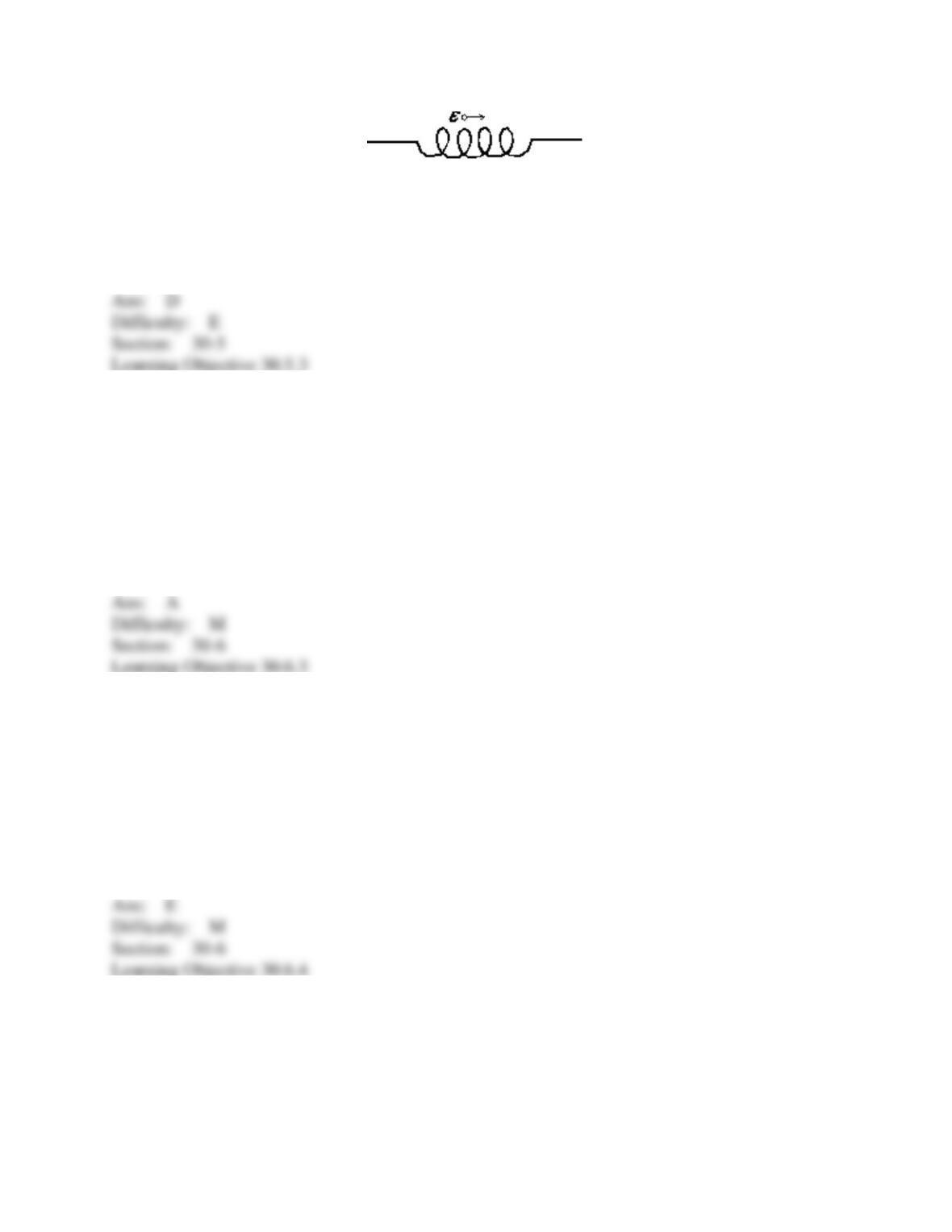
A) The current is constant and rightward
B) The current is constant and leftward
C) The current is increasing and rightward
D) The current is increasing and leftward
E) None of the above
66. An 8.0-mH inductor and a 2.0- resistor are wired in series to an ideal battery. A switch in
the circuit is closed at time t = 0, at which time the current is zero. The current reaches half its
final value at a time of:
A) 2.8 ms
B) 4.0 ms
C) 3.0 s
D) 170 s
E) 250 s
67. An inductance L, resistance R, and ideal battery of emf ℰ are wired in series. A switch in
the circuit is closed at time t = 0, at which time the current is zero. At any later time t the current
i is given by:
A) (ℰ/R)(1 – e–Lt/R)
B) (ℰ/R)e–Lt/R
C) (ℰ/R)(1 + e–Rt/L)
D) (ℰ/R)e–Rt/L
E) (ℰ/R)(1 – e–Rt/L)
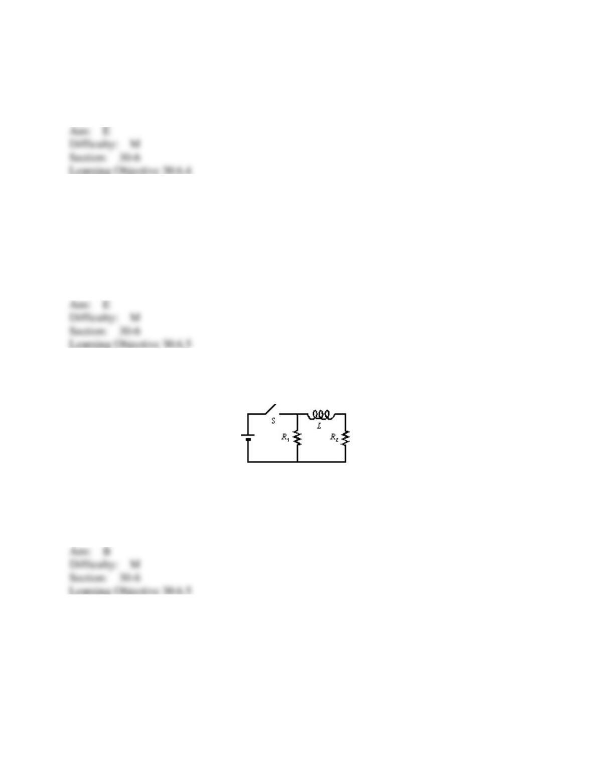
68. An inductance L, resistance R, and ideal battery of emf ℰ are wired in series. A switch in
the circuit is closed at time t = 0, at which time the current is zero. At any later time t the
potential difference across the resistor is given by:
A) ℰ(1 – e–Lt/R)
B) ℰe–Lt/R
C) ℰ(1 + e–Rt/L)
D) ℰe–Rt/L
E) ℰ(1 – e–Rt/L)
69. If both the resistance and the inductance in an LR series circuit are doubled the new
inductive time constant will be:
A) twice the old
B) four times the old
C) half the old
D) one-fourth the old
E) unchanged
70. When the switch S in the circuit shown is closed, the time constant for the growth of
current in R2 is:
A) L/R1
B) L/R2
C) L/(R1 + R2)
D) L(R1 + R2)/(R1R2)
E) (L/R1 + L/R2)/2
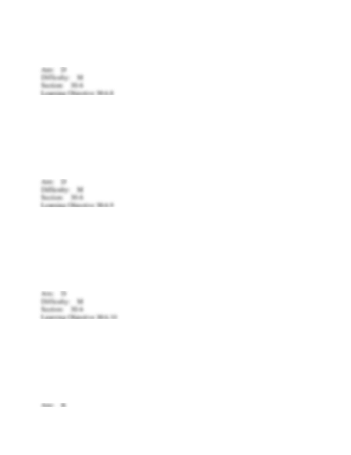
71. An inductance L, resistance R, and ideal battery of emf ℰ are wired in series and the
circuit is allowed to come to equilibrium. A switch in the circuit is opened at time t = 0, at which
time the current is ℰ/R. At any later time t the current i is given by:
A) (ℰ/R)(1 – e–Lt/R)
B) (ℰ/R)e–Lt/R
C) (ℰ/R)(1 + e–Rt/L)
D) (ℰ/R)e–Rt/L
E) (ℰ/R)(1 – e–Rt/L)
72. An inductance L, resistance R, and ideal battery of emf ℰ are wired in series and the circuit
is allowed to come to equilibrium. A switch in the circuit is opened at time t = 0, at which time
the current is ℰ/R. At any later time t the potential difference across the resistor is given by:
A) ℰ(1 – e–Lt/R)
B) ℰe–Lt/R
C) ℰ(1 + e–Rt/L)
D) ℰe–Rt/L
E) ℰ(1 – e–Rt/L)
73. An inductance L, resistance R, and ideal battery of emf ℰ are wired in series. A switch in
the circuit is closed at time t = 0, at which time the current is zero. At any later time t the emf of
the inductor is given by:
A) ℰ(1 – e–Lt/R)
B) ℰe–Lt/R
C) ℰ(1 + e–Rt/L)
D) ℰe–Rt/L
E) ℰ(1 – e–Rt/L)
74. An 8.0-mH inductor and a 2.0- resistor are wired in series to a 20-V ideal battery. A
switch in the circuit is closed at time t = 0, at which time the current is zero. After a long time the
current in the resistor and the current in the inductor are:
A) 0 A, 0 A
B) 10 A, 10 A
C) 2.5 A, 2.5 A
D) 10 A, 2.5 A
E) 10 A, 0 A
75. An 8.0-mH inductor and a 2.0- resistor are wired in series to a 20-V ideal battery. A
switch in the circuit is closed at time t = 0, at which time the current is zero. Immediately after
the switch is thrown the potential differences across the inductor and resistor are:
A) 0 V, 20 V
B) 20 V, 0 V
C) 10 V, 10 V
D) 16 V, 4 V
E) unknown since the rate of change of the current is not given
76. An inductor with inductance L and a resistor with resistance R are wired in series to an
ideal battery with emf ℰ. A switch in the circuit is closed at time t = 0, at which time the
current is zero. A long time after the switch is thrown the potential differences across the
inductor and resistor are:
A) 0, ℰ
B) ℰ, 0
C) ℰ/2, ℰ/2
D) (L/R) ℰ, (R/L) ℰ
E) unknown since the rate of change of the current is not given
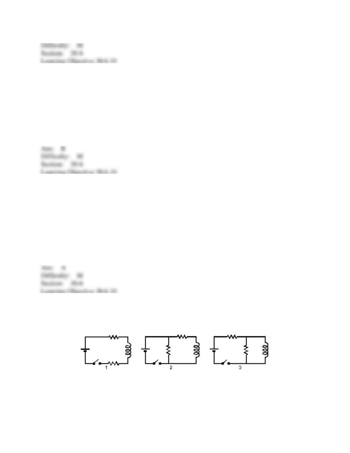
77. The diagrams show three circuits with identical batteries, identical inductors, and identical
resistors. Rank them according to the current through the battery just after the switch is closed,
from least to greatest.
A) 3, 2, 1
B) 2 and 3 tie, then 1
C) 1, 3, 2
D) 1, 2, 3
E) 2, 3, 1
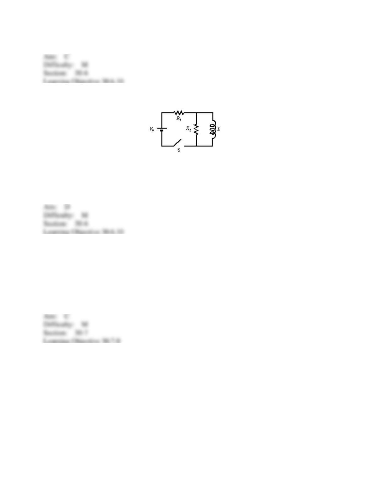
78. Immediately after switch S in the circuit shown is closed, the current through the battery is:
A) 0
B) V0/R1
C) V0/R2
D) V0/(R1 + R2)
E) V0(R1 + R2)/(R1R2)
79. A 6.0 mH inductor is in a circuit. At the instant the current is 5.0 A and its rate of change is
200 A/s, the rate with which the energy stored in the inductor is increasing is:
A) 7.5 10–2 W
B) 3.0 W
C) 6.0 W
D) 120 W
E) 240 W
80. An inductance L and a resistance R are connected in series to an ideal battery. A switch in
the circuit is closed at time t = 0, at which time the current is zero. The rate of increase of the
energy stored in the inductor is a maximum:
A) just after the switch is closed
B) at the time t = L/R after the switch is closed
C) at the time t = 2L/R after the switch is closed
D) at the time t = (L/R)ln 2 after the switch is closed
E) a long time after the switch is closed
81. The stored energy in an inductor:
A) depends, in sign, upon the direction of the current
B) depends on the rate of change of current
C) is proportional to the square of the inductance
D) has units J/H
E) is none of the above
82. An inductance L and a resistance R are connected in series to an ideal battery. A switch in
the circuit is closed at time t = 0, at which time the current is zero. The energy stored in the
inductor is a maximum:
A) just after the switch is closed
B) at the time t = L/R after the switch is closed
C) at the time t = L/R2 after the switch is closed
D) at the time t = 2L/R after the switch is closed
E) a long time after the switch is closed
83. In each of the following operations, energy is expended. The LEAST percentage of
returnable electrical energy will be yielded by:
A) charging a capacitor
B) charging a storage battery
C) sending current through a resistor
D) establishing a current through an inductor
E) moving a conducting rod through a magnetic field
84. A current of 10 A in a certain inductor results in a stored energy of 40 J. When the current
is changed to 5 A in the opposite direction, the stored energy changes by:
A) 20 J
B) 30 J
C) 40 J
D) 50 J
E) 60 J
85. A 6.0 mH inductor is in a series circuit with a resistor and an ideal battery. At the instant
the current in the circuit is 5.0 A the energy stored in the inductor is:
A) 0 J
B) 7.5 10–2 J
C) 15 10–2 J
D) 30 10–2 J
E) unknown since the rate of change of the current is not given
86. A 6.0-mH inductor and a 3.0- resistor are wired in series to a 12-V ideal battery. A switch
in the circuit is closed at time t = 0, at which time the current is zero. 2.0 ms later the energy
stored in the inductor is:
A) 0 J
B) 9.6 10–3 J
C) 1.9 10–2 J
D) 2.5 10–2 J
E) 3.8 10–2 J
87. The quantity (B2/
o) has units of:
A) J
B) J/H
C) J/m
D) J/m3
E) H/m3
88. A 0.20-cm radius cylinder, 3.0 cm long, is wrapped with wire to form an inductor. At the
instant the magnetic field in the interior is 5.0 mT, the energy stored in the field is:
A) 0 J
B) 3.8 10–6 J
C) 7.5 10–6 J
D) 7.5 10–4 J
E) 9.9 J
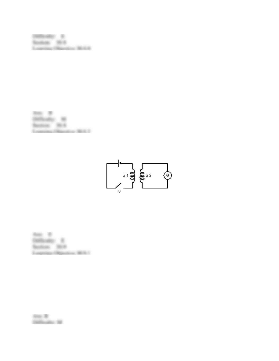
89. In the diagram, assume that all the magnetic field lines generated by coil 1 pass through
coil 2. Coil 1 has 100 turns and coil 2 has 400 turns. Then:
A) the currents will be the same in the two coils
B) the emf around coil 1 will be 1/4 the emf around coil 2
C) the current in coil 1 will be 1/4 the current in coil 2
D) the emfs will be the same in the two coils
E) none of the above
90. Two coils have a mutual inductance of 3.5 mH. If the current in one coil is changing at a rate
of 4.8 A/s, what is the emf induced in the second coil?
A) 7.3 x 10⁻⁴ V
B) 0.017 V
C) 1400 V
D) cannot tell without knowing the inductance of the second coil
E) cannot tell without knowing the current in the second coil