in 1 is:
A) the same as that in 2
B) twice that in 2
C) half that in 2
D) four times that in 2
E) one fourth that in 2
41. Resistor 1 has twice the resistance of resistor 2. They are connected in parallel to a battery.
The ratio of the thermal energy dissipation by 1 to that by 2 is:
A) 1:4
B) 1:2
C) 1:1
D) 2:1
E) 4:1
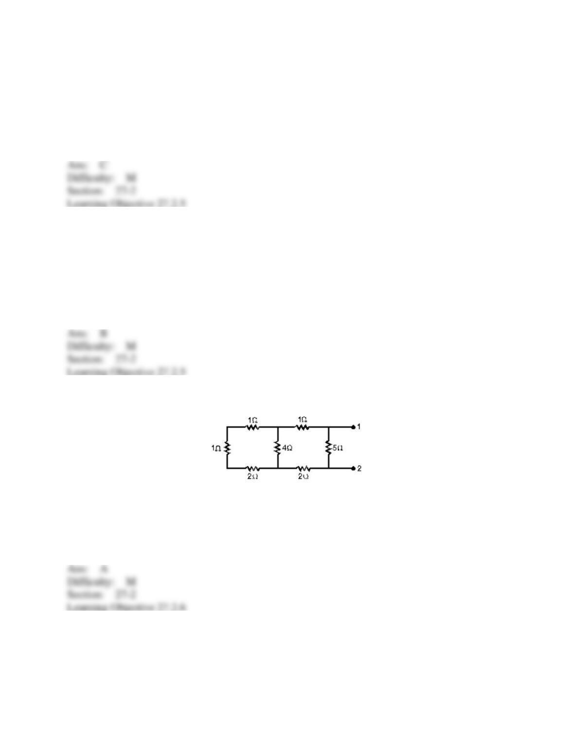
42. The equivalent resistance between points 1 and 2 of the circuit shown is:
A) 2.5
B) 4.0
C) 5.0
D) 6.5
E) 16
43. Each of the resistors in the diagram is 12 . The resistance of the entire circuit is:
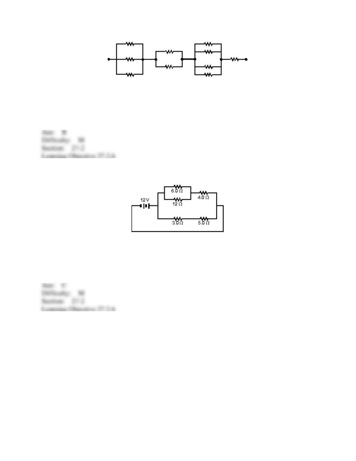
A) 5.8
B) 25
C) 48
D) 120
E) none of these
44. The current in the 5.0- resistor in the circuit shown is:
A) 0.42 A
B) 0.67 A
C) 1.5 A
D) 2.4 A
E) 3.0 A
45. In the diagrams, all light bulbs are identical and all emf devices are identical. In which
circuit (I, II, III, IV, V) will the bulbs glow with the same brightness as in circuit X?
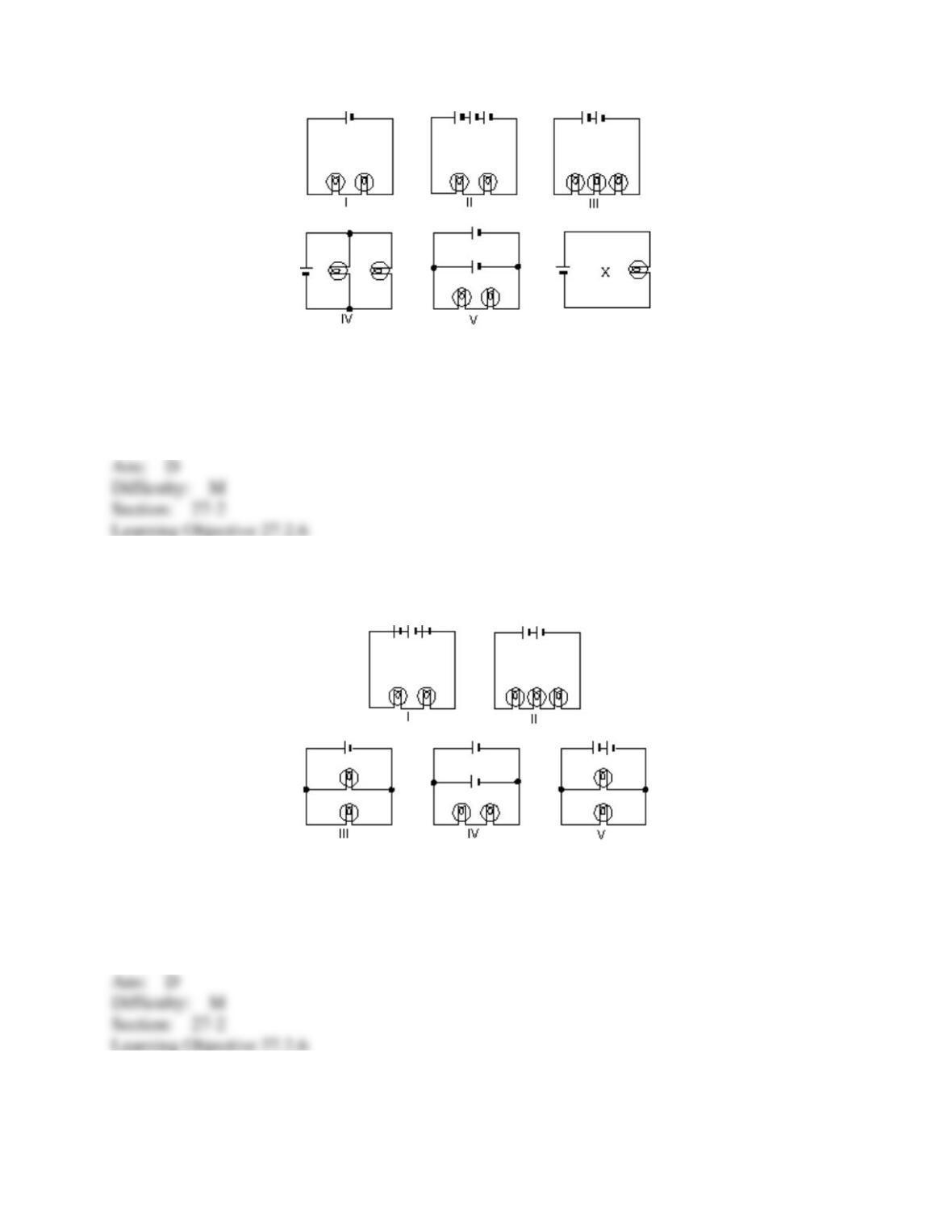
A) I
B) II
C) III
D) IV
E) V
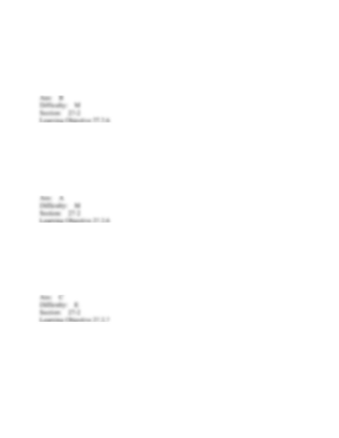
46. In the diagrams, all light bulbs are identical and all emf devices are identical. In which
circuit (I, II, III, IV, V) will the bulbs be dimmest?
A) I
B) II
C) III
D) IV
E) V
47. A 3- and a 1.5- resistor are wired in parallel and the combination is wired in series to a
4- resistor and a 10-V emf device. The current in the 3- resistor is:
A) 0.33 A
B) 0.67 A
C) 2.0 A
D) 3.3 A
E) 6.7 A
48. A 3- and a 1.5- resistor are wired in parallel and the combination is wired in series to a
4- resistor and a 10-V emf device. The potential difference across the 3- resistor is:
A) 2.0 V
B) 6.0 V
C) 8.0 V
D) 10 V
E) 12 V
49. For any circuit the number of independent equations containing emf’s, resistances, and
currents equals:
A) the number of junctions
B) the number of junctions minus 1
C) the number of branches
D) the number of branches minus 1
E) the number of closed loops
50. If a circuit has L closed loops, B branches, and J junctions the number of independent loop
equations is:
A) B – J + 1
B) B – J
C) B
D) L
E) L – J
51. Two identical batteries, each with an emf of 18 V and an internal resistance of 1 , are
wired in parallel by connecting their positive terminals together and connecting their negative
terminals together. The combination is then wired across a 4- resistor. The current in the 4-
resistor is:
A) 2.0 A
B) 3.6 A
C) 4.0 A
D) 7.2 A
E) 9.0 A
52. Two identical batteries, each with an emf of 18 V and an internal resistance of 1 , are
wired in parallel by connecting their positive terminals together and connecting their negative
terminals together. The combination is then wired across a 4- resistor. The current in each
battery is:
A) 1.0 A
B) 2.0 A
C) 3.6 A
D) 4.0 A
E) 4.5 A
53. Two identical batteries, each with an emf of 18 V and an internal resistance of 1 , are
wired in parallel by connecting their positive terminals together and connecting their negative
terminals together. The combination is then wired across a 4- resistor. The potential difference
across the 4- resistor is:
A) 4.0 V
B) 8.0 V
C) 14 V
D) 16 V
E) 29 V
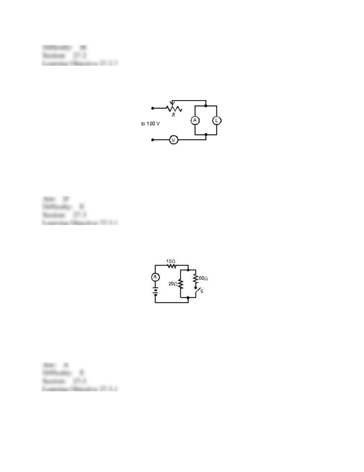
54. The circuit shown was wired for the purpose of measuring the resistance of the lamp L.
Inspection shows that:
A) voltmeter V and rheostat R should be interchanged
B) the circuit is satisfactory
C) the ammeter A should be in parallel with R, not L
D) the meters, V and A, should be interchanged
E) L and V should be interchanged
55. When switch S is open, the ammeter in the circuit shown reads 2.0 A. When S is closed,
the ammeter reading:
A) increases slightly
B) remains the same
C) decreases slightly
D) doubles
E) halves
56. A certain galvanometer has a resistance of 100 and requires 1 mA for full scale
deflection. To make this into a voltmeter reading 1 V full scale, connect a resistance of:
A) 1000 in parallel
B) 900 in series
C) 1000 in series
D) 10 in parallel
E) 0.1 in series
57. In the figure, voltmeter V1 reads 600 V, voltmeter V2 reads 580 V, and ammeter A reads
100 A. The power wasted in the transmission line connecting the power house to the consumer
is:
A) 1 kW
B) 2 kW
C) 58 kW
D) 59 kW
E) 60 kW
58. To make a galvanometer into an ammeter, connect:
A) a high resistance in parallel
B) a high resistance in series
C) a low resistance in series
D) a low resistance in parallel
E) a source of emf in series
59. A certain voltmeter has an internal resistance of 10,000 and a range from 0 to 100 V. To
give it a range from 0 to 1000 V, one should connect:
A) 100,000 in series
B) 100,000 in parallel
C) 1000 in series
D) 1000 in parallel
E) 90,000 in series
60. A certain ammeter has an internal resistance of 1 and a range from 0 to 50 mA. To make
its range from 0 to 5 A, use:
A) a series resistance of 99
B) an extremely large (say 106 ) series resistance
C) a resistance of 99 in parallel
D) a resistance of 1/99 in parallel
E) a resistance of 1/1000 in parallel
61. A galvanometer has an internal resistance of 12 and requires 0.01 A for full scale
deflection. To convert it to a voltmeter reading 3 V full scale, one must use a series resistance of:
A) 102
B) 288
C) 300
D) 360
E) 412
62. A certain voltmeter has an internal resistance of 10,000 and a range from 0 to 12 V. To
extend its range to 120 V, use a series resistance of:
A) 1,111
B) 90,000
C) 100,000
D) 108,000
E) 120,000
63. The time constant RC has units of:
A) second/farad
B) second/ohm
C) 1/second
D) second/watt
E) none of these
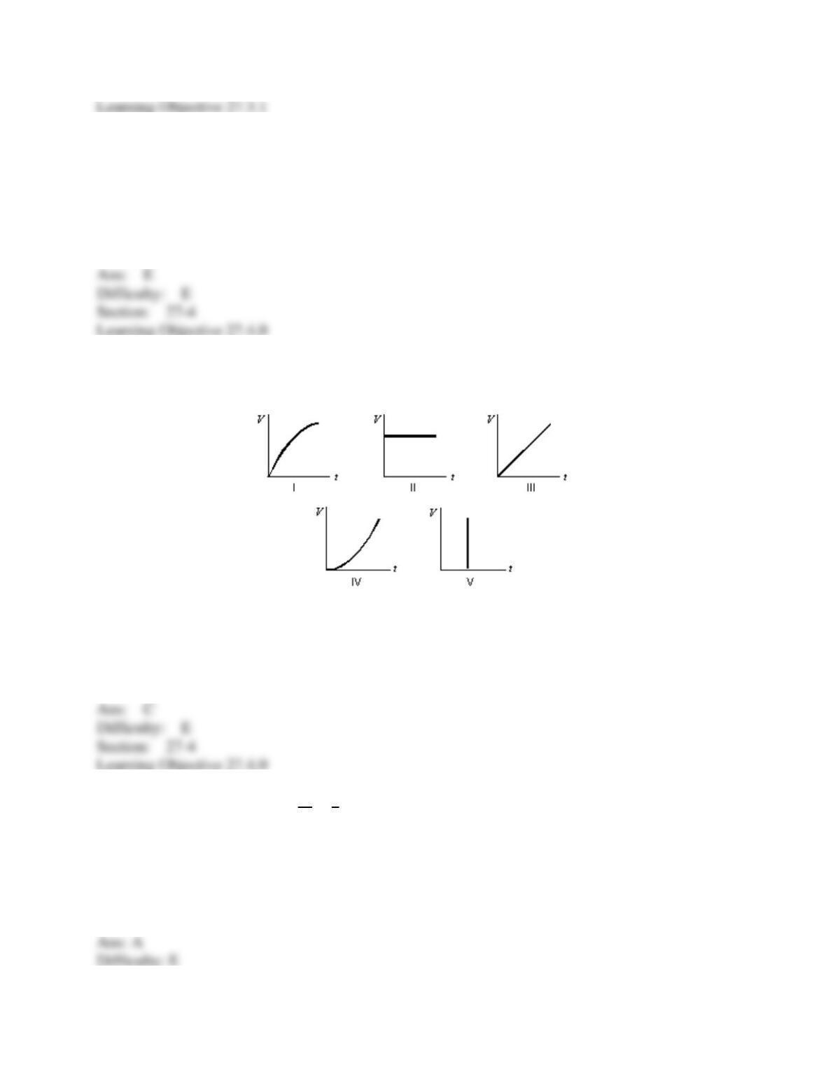
64. Suppose the current charging a capacitor is kept constant. Which graph below correctly
gives the potential difference V across the capacitor as a function of time?
A) I
B) II
C) III
D) IV
E) V
65. Here is a loop equation: 𝑅𝑑𝑞
𝑑𝑡 +𝑞
𝐶= ℰ. What does this equation represent?
A) a charging capacitor
B) a discharging capacitor
C) a capacitor that has been disconnected
D) a charging resistor
E) an oscillating circuit
66. A certain capacitor, in series with a resistor, is being charged. At the end of 10 ms its
charge is half the final value. The time constant for the process is about:
A) 5.0 ms
B) 6.9 ms
C) 10 ms
D) 14 ms
E) 20 ms
67. In the capacitor discharge formula q = q0e–t/RC the symbol t represents:
A) the time constant
B) the time it takes for C to lose the fraction 1/e of its initial charge
C) the time it takes for C to lose the fraction (1 – 1/e) of its initial charge
D) the time it takes for C to lose essentially all of its initial charge
E) none of the above
68. A charged capacitor is being discharged through a resistor. At the end of one time constant
the charge has been reduced by (1 – 1/e) = 63% of its initial value. At the end of two time
constants the charge has been reduced by what percent of its initial value?
A) 82%
B) 86%
C) 100%
D) between 90% and 100%
E) need to know more data to answer the question
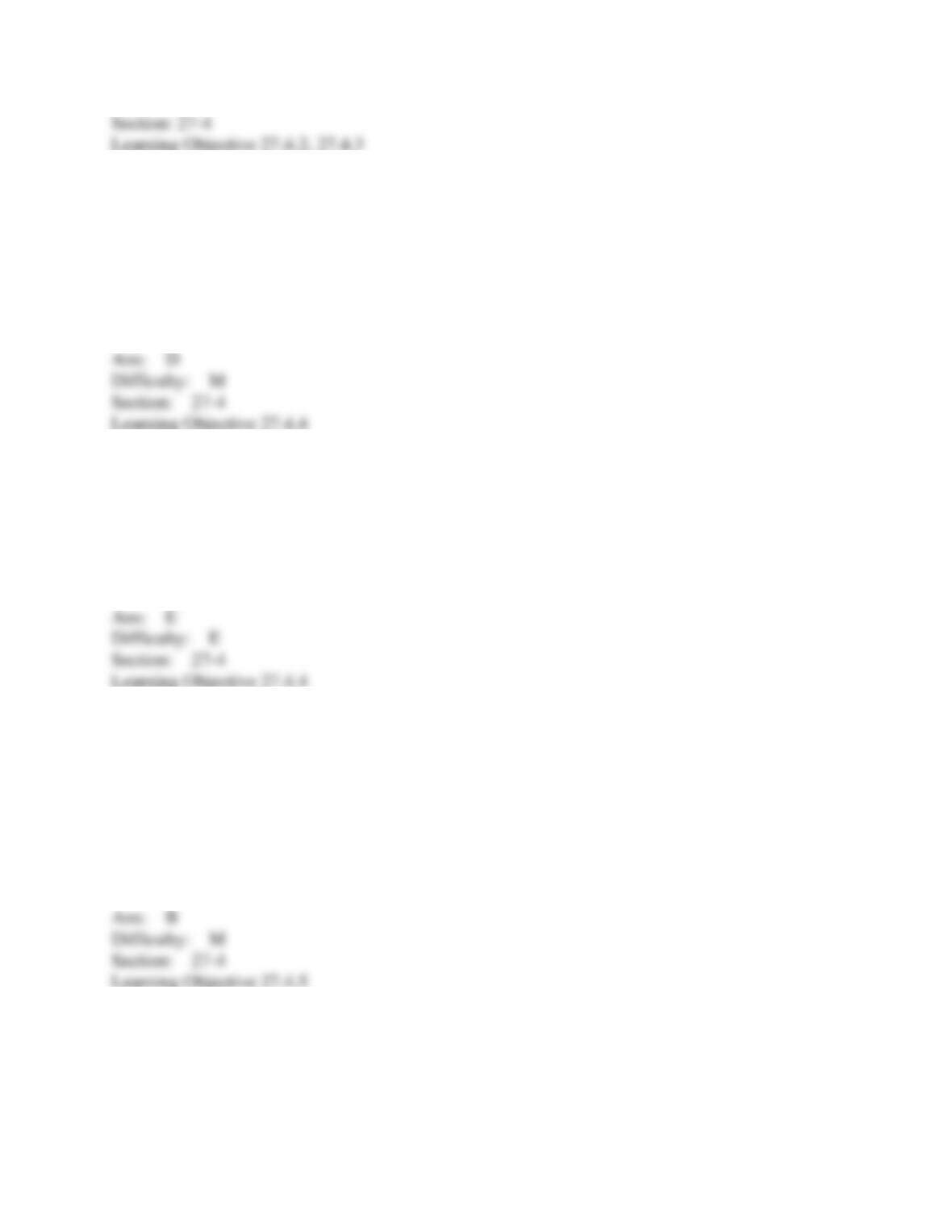
69. Four circuits have the form shown in the diagram. The capacitor is initially uncharged
and the switch S is open.
The values of the emf ℰ, resistance and R, and capacitance C for each for the circuits are
circuit 1: ℰ = 18 V, R = 3 , C = 1
F
circuit 2: ℰ = 18 V, R = 6 , C = 9
F
circuit 3: ℰ = 12 V, R = 1 , C = 7
F
circuit 4: ℰ = 10 V, R = 5 , C = 7
F
Rank the circuits according to the current just after switch S is closed least to greatest.
A) 1, 2, 3, 4
B) 4, 3, 2, 1
C) 4, 2, 3, 1
D) 4, 2, 1, 3
E) 3, 1, 2, 4
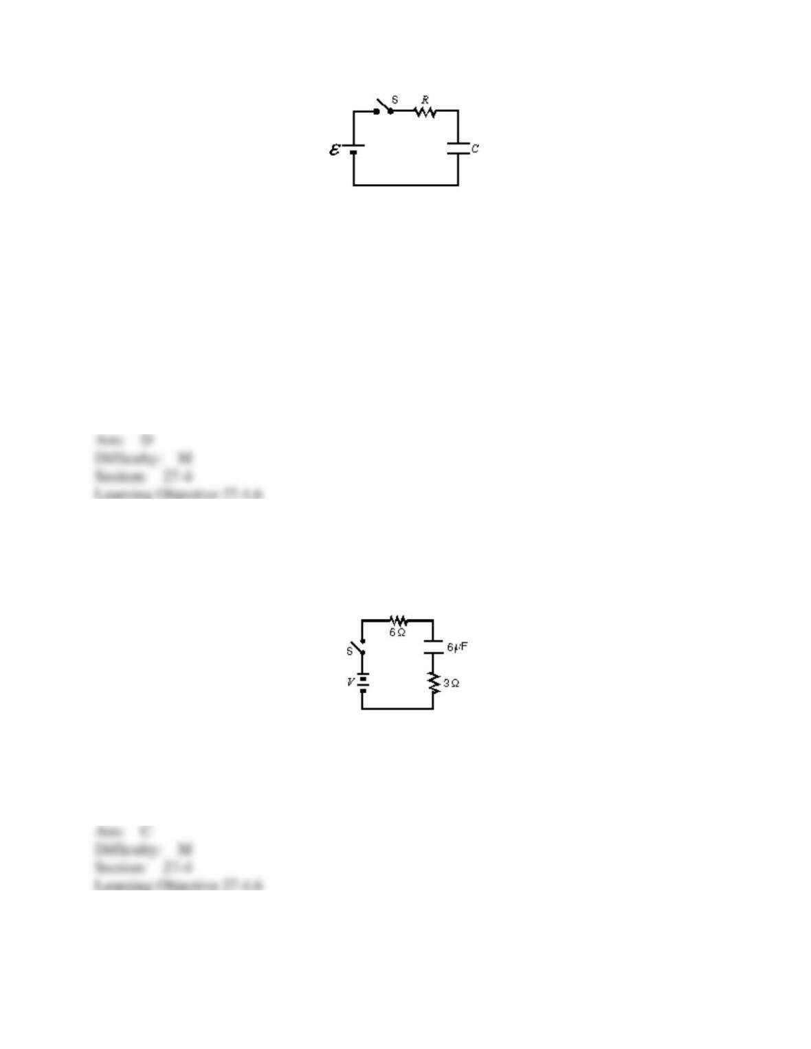
70. In the circuit shown, the capacitor is initially uncharged, and V = 10 V. At time t = 0,
switch S is closed. If denotes the time constant, the approximate current through the 3
resistor when
t = /10 is:
A) 0.50 A
B) 0.75 A
C) 1.0 A
D) 1.5 A
E) 3.0 A
71. Four circuits have the form shown in the diagram. The capacitor is initially uncharged
and the switch S is open.
The values of the emf ℰ, resistance R, and the capacitance C for each of the circuits are
circuit 1: ℰ = 18 V, R = 3 , C = 1
F
circuit 2: ℰ = 18 V, R = 6 , C = 9
F
circuit 3: ℰ = 12 V, R = 1 , C = 7
F
circuit 4: ℰ = 10 V, R = 5 , C = 7
F
Rank the circuits according to the time after switch S is closed for the capacitors to reach half
their final charges, least to greatest.
A) 1, 2, 3, 4
B) 2, 4, 3, 1
C) 1, 3, 4, 2
D) 4, 2, 1, 3
E) 3, 1, 2, 4
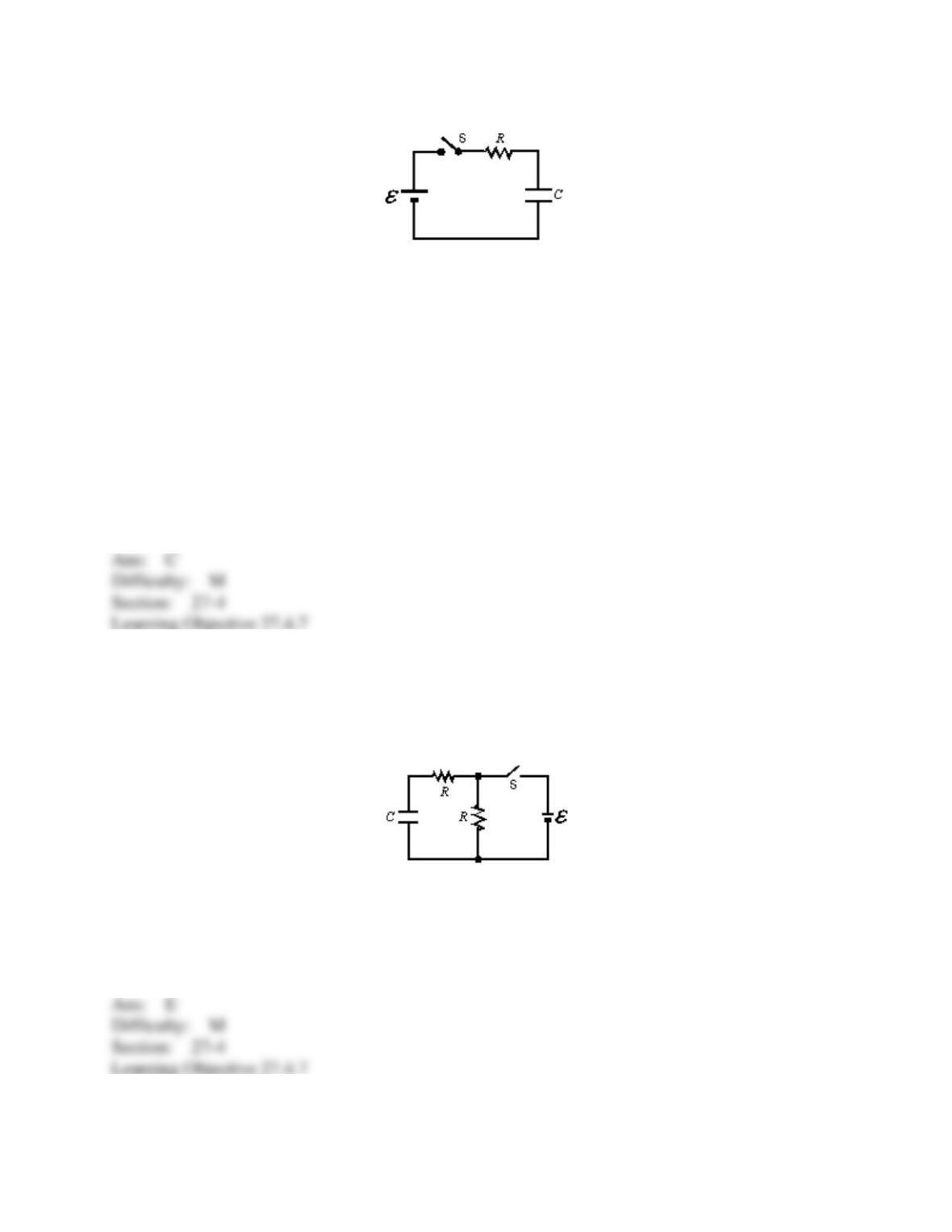
72. In the circuit shown, both resistors have the same value R. Suppose switch S is initially
closed and capacitor C is charged. When switch S is then opened, the circuit has a time constant
a. Conversely, suppose S is initially open and capacitor C is uncharged. When switch S is then
closed, the circuit has a time constant b. The ratio a/b is:
A) 0.5
B) 0.67
C) 1
D) 1.5
E) 2
73. A certain capacitor, in series with a 720- resistor, is being charged. At the end of 10 ms
its charge is half the final value. The capacitance is about:
A) 9.6
F
B) 14
F
C) 20
F
D) 7.2 F
E) 10 F
74. An initially uncharged capacitor C is connected in series with resistor R. This combination
is then connected to a battery of emf V0. Sufficient time elapses so that a steady state is
reached. Which of the following statements is NOT true?
A) The time constant is independent of V0
B) The final charge on C is independent of R
C) The total energy dissipated by R is independent of R
D) The total energy dissipated by R is independent of V0
E) The initial current (just after the battery was connected) is independent of C