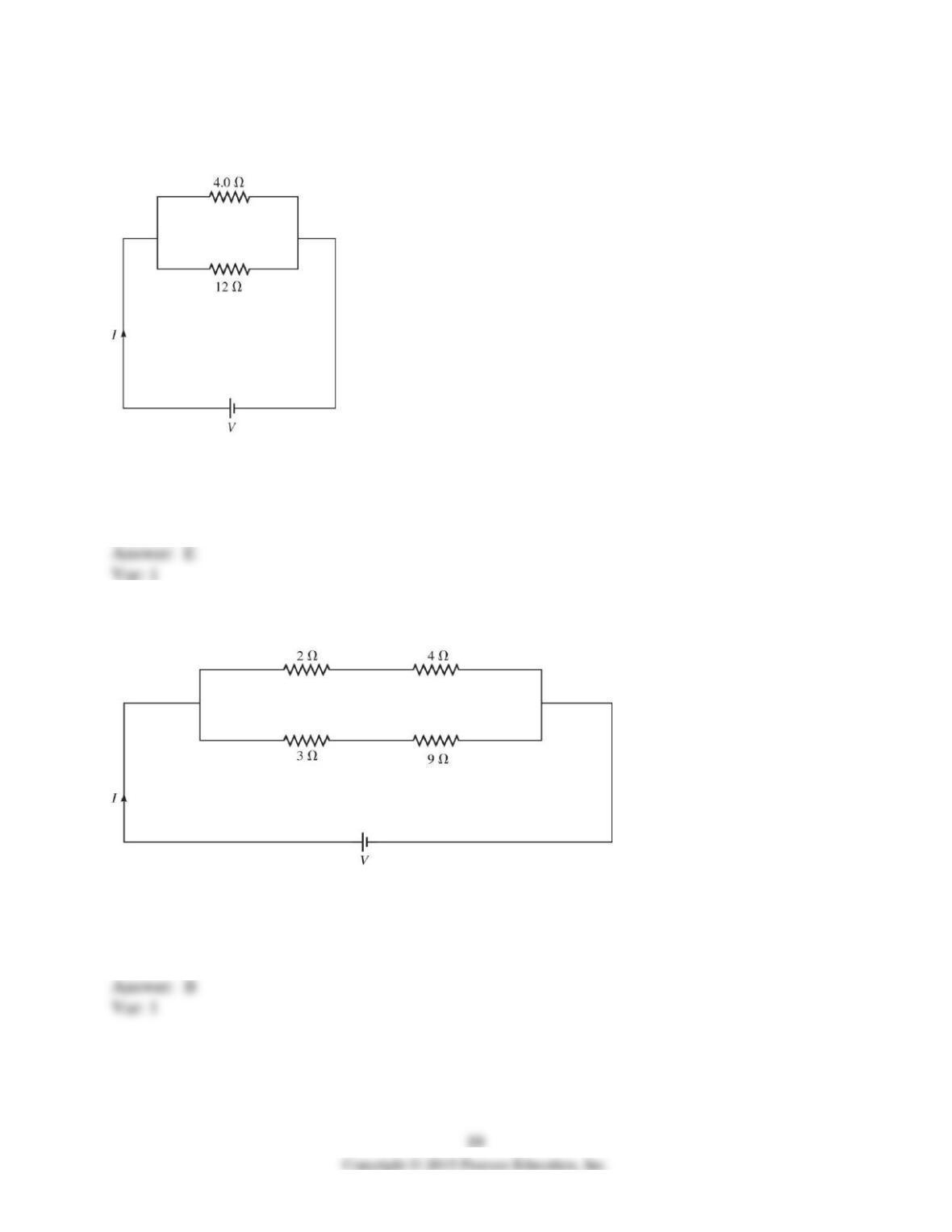
70) A 4.0-Ω resistor is connected with a 12–Ω resistor and this combination is connected across
an ideal dc power supply with V = 6.0 V, as shown in the figure. When a total current I flows
from the power supply, what is the current through the 12-Ω resistor?
A) 1.5 A
B) 2.0 A
C) 2.5 A
D) 3.0 A
E) 0.50 A
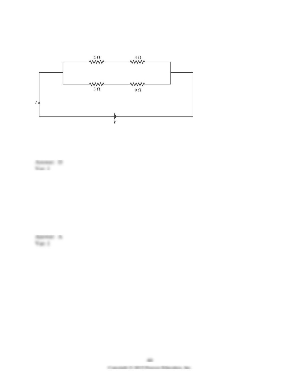
71) Four resistors are connected across an ideal dc battery with voltage V, as shown in the figure.
If the total current in this circuit is I = 1 A, what is the value of the voltage V?
A) 2 V
B) 4 V
C) 6 V
D) 8 V
E) 10 V
72) Four resistors are connected across an ideal dc battery with voltage V as shown in the figure.
Assume that all quantities shown are accurate to two significant figures. If the total current
through this circuit is I = 2.0 A, what is the current through the 4.0-Ω resistor?
A) 1.0 A
B) 2.0 A
C) 3.0 A
D) 1.3 A
E) 2.4 A
73) An ideal 100-V dc battery is applied across a series combination of four resistors having
resistances of 20 Ω, 40 Ω, 60 Ω, and 80 Ω. What is the potential difference across the 40-Ω
resistor?
A) 20 V
B) 40 V
C) 60 V
D) 80 V
E) 100 V
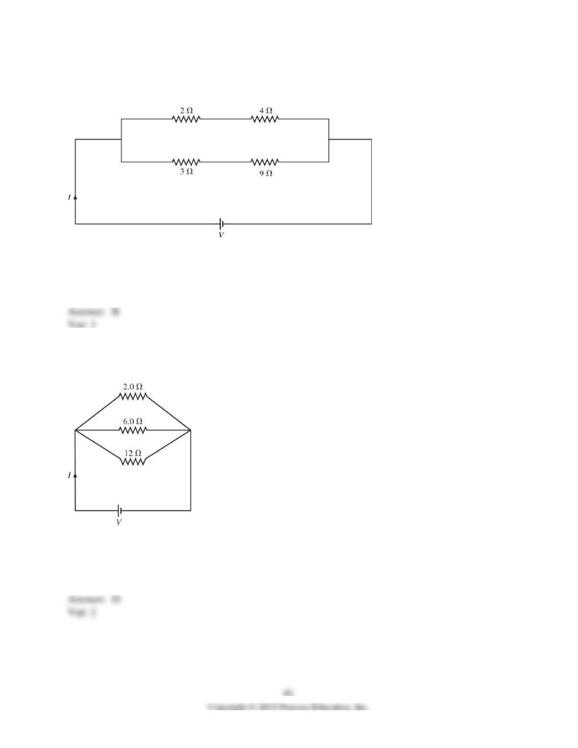
74) Four resistors are connected across an ideal dc source of V = 8.0 V, as shown in the figure.
Assume all resistances shown are accurate to two significant figures. What is the current through
the 9.0-Ω resistor?
A) 1.0 A
B) 0.67 A
C) 0.50 A
D) 0.90 A
E) 2.0 A
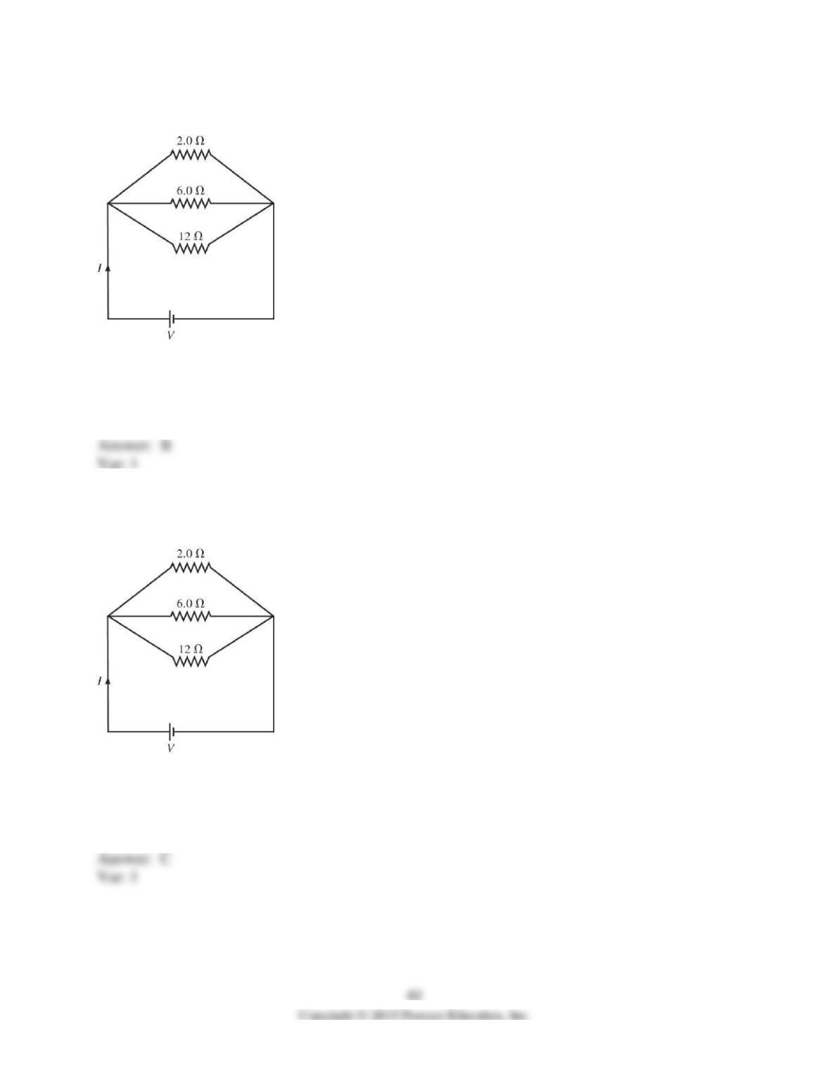
75) Three resistors with resistances of 2.0 Ω, 6.0 Ω, and 12 Ω are connected across an ideal dc
voltage source V as shown in the figure. If the total current through the circuit is I = 2.0 A, what
is the applied voltage V?
A) 6.0 V
B) 3.0 V
C) 2.0 V
D) 2.7 V
E) 1.5 V
76) Three resistors with resistances of 2.0 Ω, 6.0 Ω, and 12 Ω are connected across an ideal dc
voltage source V = 2.0 V, as shown in the figure. What is the total current I in this circuit?
A) 0.70 A
B) 1.5 A
C) 2.0 A
D) 3.0 A
E) 6.0 A
77) Three resistors with resistances of 2.0 Ω, 6.0 Ω, and 12 Ω are connected across an ideal dc
voltage source V, as shown in the figure. If the total current in the circuit is I = 5.0 A, what is the
current through the 12-Ω resistor?
A) 1.7 A
B) 2.5 A
C) 0.56 A
D) 5.0 A
E) 0.75 A
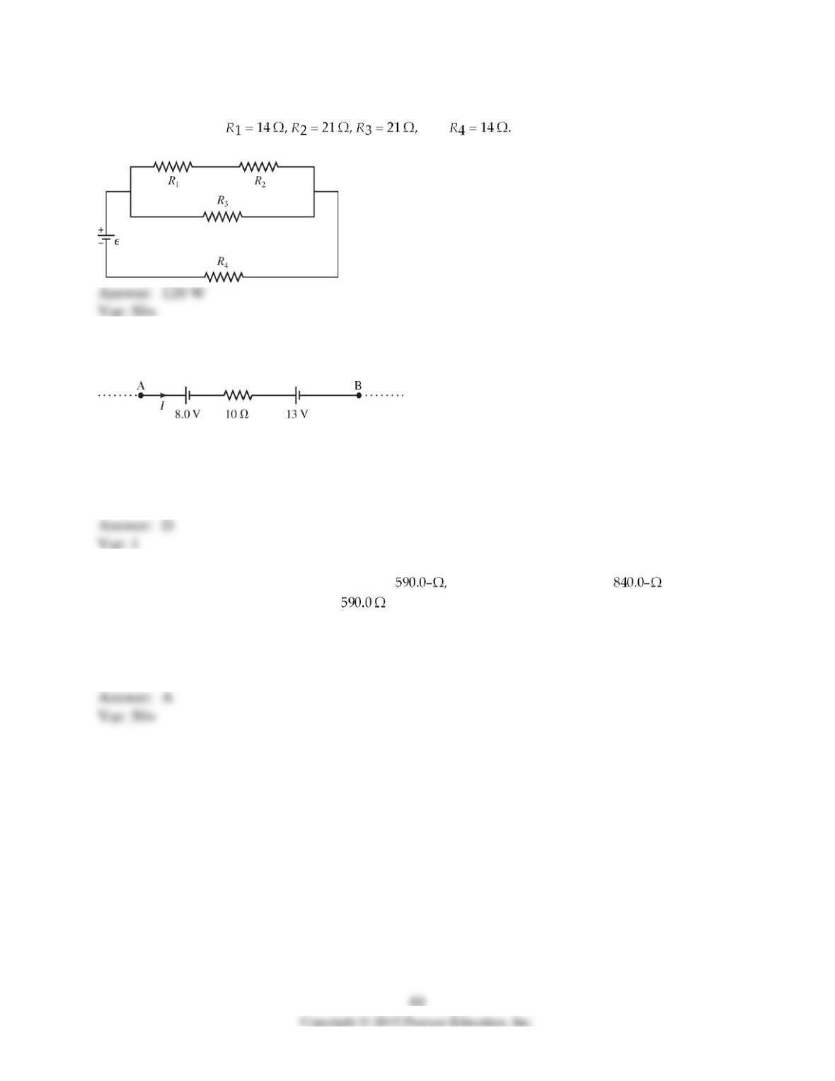
78) For the circuit shown in the figure, the ideal battery has an emf ε = 80 V. The four resistors
have resistances of and Calculate the rate at which heat is
being generated in the resistor R4.
79) A portion of a circuit is shown in the figure, and the batteries are ideal. What is the potential
difference VA – VB if I = 5.0 A?
A) 63 V
B) 35 V
C) 55 V
D) 45 V
E) 71 V
80) An ideal 10.0-V dc is connected across a resistor in series with an resistor.
What is the potential drop across the resistor?
A) 4.1 V
B) 5.9 V
C) 14 V
D) 7.0 V
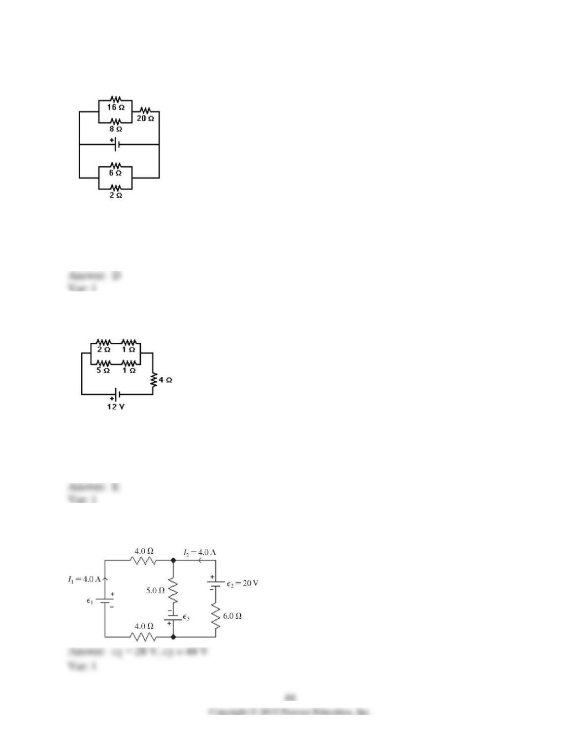
81) For the circuit shown in the figure, the current in the 8.0-Ω resistor is 0.50A. What is the
current in the 2.0-Ω resistor? All the numbers shown are accurate to two significant figures.
A) 2.25 A
B) 0.75 A
C) 4.5 A
D) 9.5 A
E) 6.4 A
82) For the circuit shown in the figure, what is the power dissipated in the 2.0-Ω resistor? All the
numbers shown are accurate to three significant figures.
A) 5.33 W
B) 8.00 W
C) 6.67 W
D) 2.67 W
E) 3.56 W
83) For the circuit shown in the figure, calculate the emf’s ε1 and ε3, assuming that the batteries
are ideal. Note that two currents are shown.
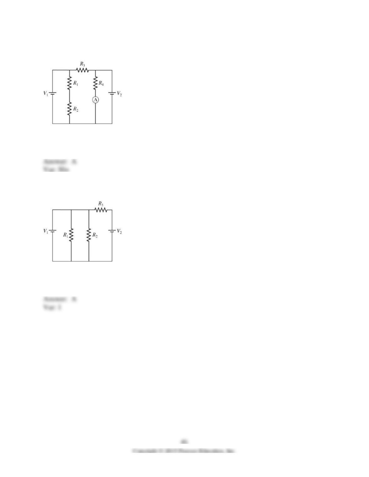
84) In the circuit shown in the figure, R1 = R2 = 90.0 Ω, R3 = R4 = 20.0 Ω, V1 = 7.0 V, V2 = 8.0
V, and the batteries are both ideal. What current does the ammeter read?
A) 0.40 A
B) 0.050 A
C) 0.83 A
D) 0.056 A
85) In the circuit shown in the figure, R1 = 60 Ω, R2 = 120 Ω, R3 = 180 Ω, V1 = 3.0 V, V2 = 6.0
V, and the batteries are both ideal. What is the current through R1?
A) 0.050 A
B) 0.030 A
C) 0.00 A
D) 2.68 A
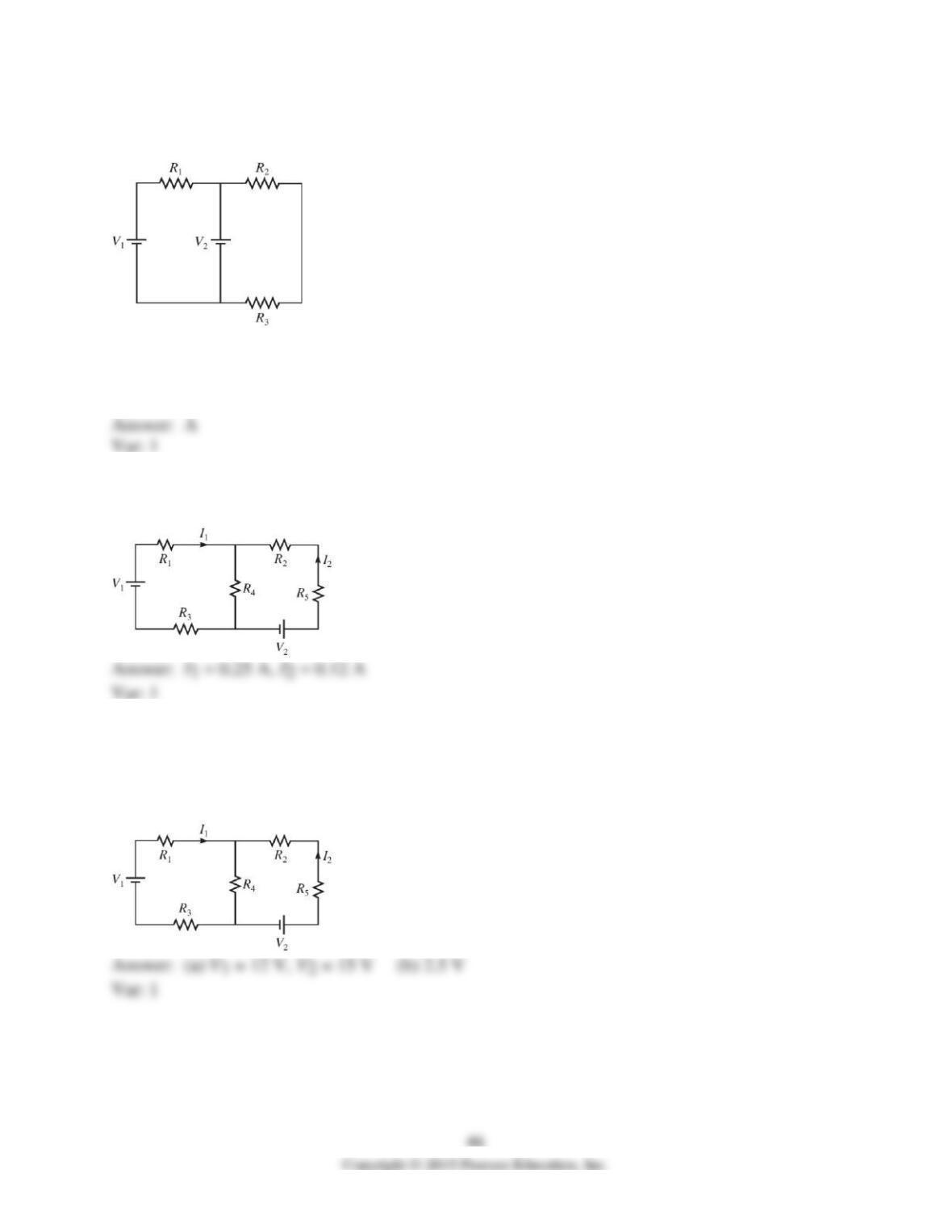
86) In the circuit shown in the figure, R1 = 10 Ω, R2 = 12 Ω, R3 = 20 Ω, V1 = 1.0 V, V2 = 7.0 V,
and the batteries are both ideal. What is the current through R1?
A) 0.60 A
B) 0.80 A
C) 0.18 A
D) 0.13 A
87) For the circuit shown in the figure, R1 = 18 Ω, R2 = 44 Ω, R3 = 33 Ω, R4 = 14 Ω, R5 = 12 Ω,
V1 = 18 V, V2 = 12 V, and the batteries are ideal. Determine I1 and I2.
88) For the circuit shown in the figure, R1 = 50 Ω, R2 = 20 Ω, R3 = 35 Ω, R4 = 10 Ω, R5 = 68 Ω,
I1 = 0.111 A, I2 = 0.142 A, and the batteries are ideal.
(a) Determine V1 and V2.
(b) What is the potential difference across R4?
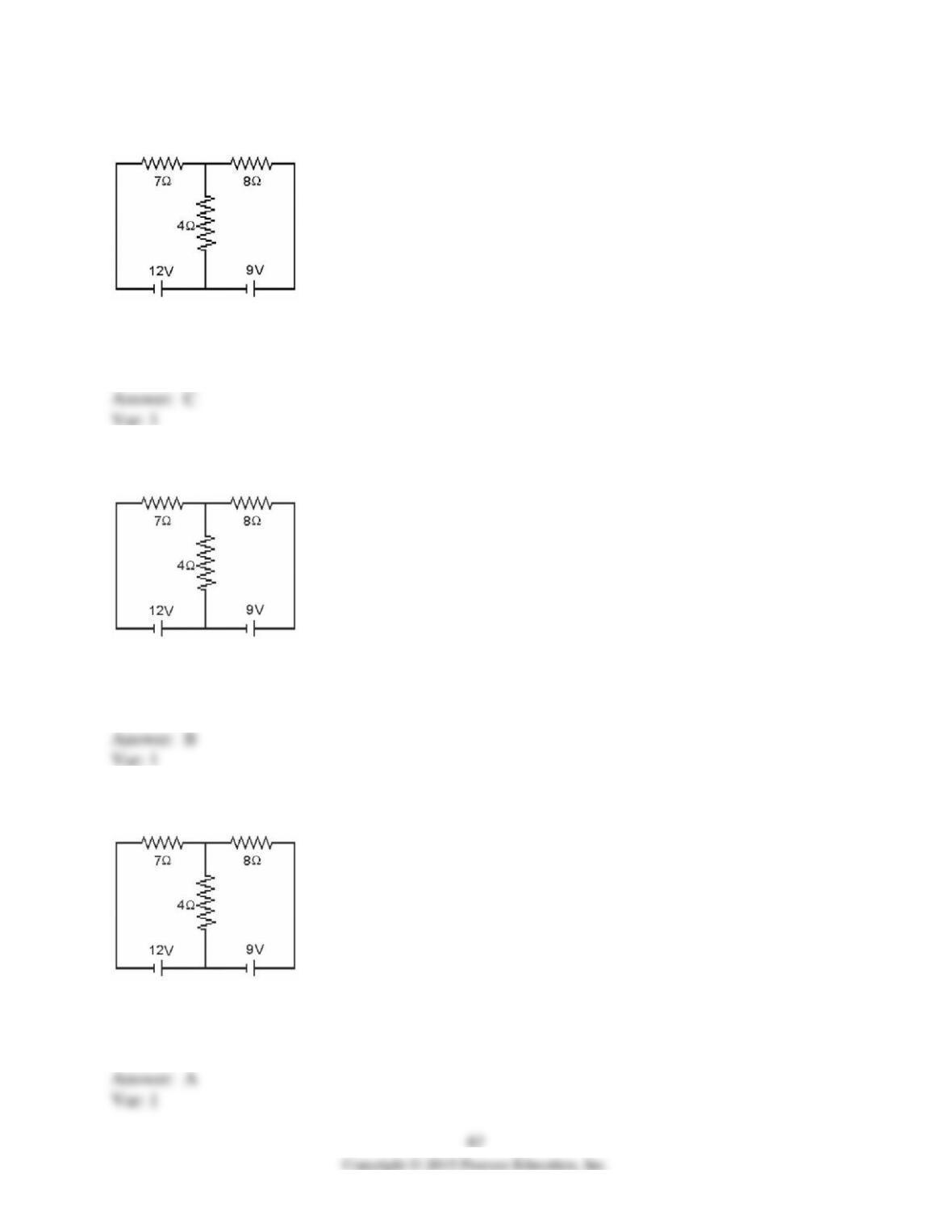
89) Determine the current in the 7.0-Ω resistor for the circuit shown in the figure. Assume that
the batteries are ideal and that all numbers are accurate to two significant figures.
A) 0.28 A
B) 1.3 A
C) 1.6 A
D) 2.1 A
90) Determine the current in the 8.0-Ω resistor for the circuit shown in the figure. Assume that
the batteries are ideal and that all numbers are accurate to two significant figures.
A) 0.28 A
B) 1.3 A
C) 1.6 A
D) 2.1 A
91) Determine the current in the 4.0-Ω resistor for the circuit shown in the figure. Assume that
the batteries are ideal and that all numbers are accurate to two significant figures.
A) 0.28 A
B) 1.3 A
C) 1.6 A
D) 2.1 A
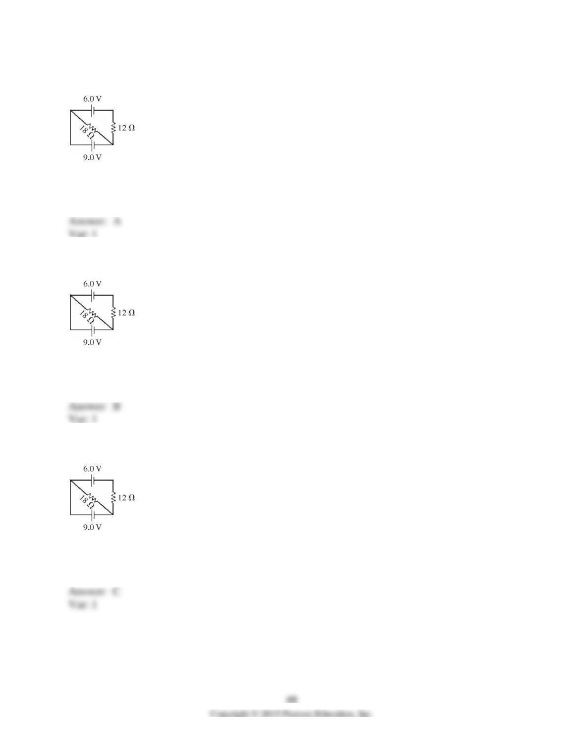
92) Determine the current in the 12-Ω resistor for the circuit shown in the figure assuming that
the batteries are ideal.
A) 0.25 A
B) 0.50 A
C) 0.75 A
D) 1.0 A
93) Determine the current in the 18-Ω resistor for the circuit shown in the figure assuming that
the batteries are ideal.
A) 0.25 A
B) 0.50 A
C) 0.75 A
D) 1.0 A
94) For the circuit shown in the figure, both batteries are ideal. What current flows in the solid
wire connecting the upper left and lower left corners of the circuit?
A) 0.25 A
B) 0.50 A
C) 0.75 A
D) 1.0 A
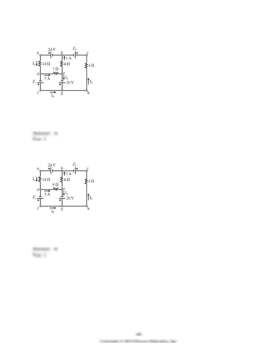
95) A multiloop circuit is shown in the figure. Find the current I1 if the batteries are ideal. (It is
not necessary to solve the entire circuit.)
A) -2 A
B) 2 A
C) 6 A
D) -5 A
E) 0 A
96) A multiloop circuit is shown in the figure. Find the current I2 if the batteries are ideal. (It is
not necessary to solve the entire circuit.)
A) -3 A
B) 3 A
C) 7 A
D) -7 A
E) 0 A
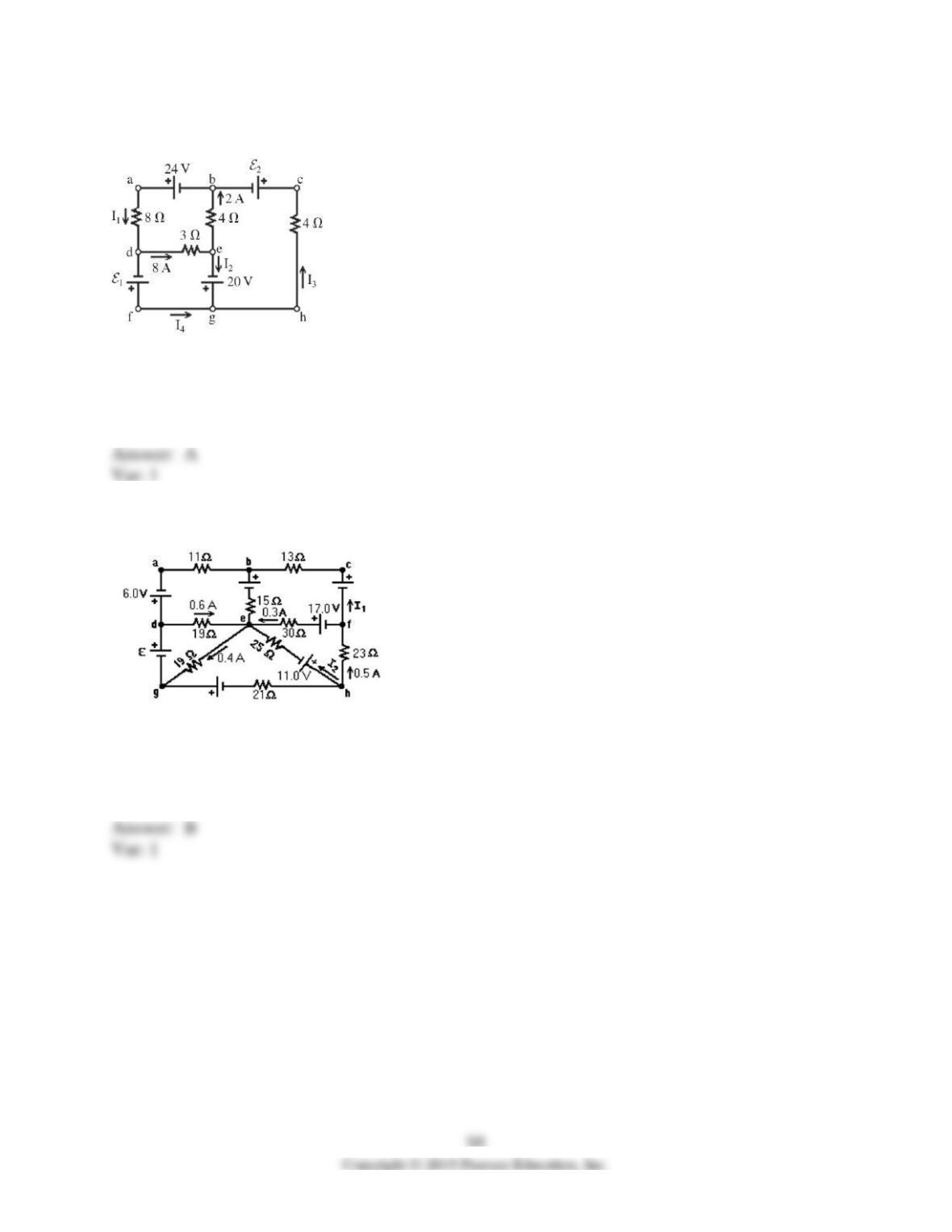
97) A multiloop circuit is shown in the figure. Find the emf ε1 if the batteries are ideal. (It is not
necessary to solve the entire circuit.)
A) -4 V
B) 4 V
C) 44 V
D) 52 V
E) -52 V
98) A multiloop circuit is shown in the figure, but some quantities are not labeled. Find the emf ε
if the batteries are ideal. (It is not necessary to solve the entire circuit.)
A) +3 V
B) +19 V
C) -3 V
D) -10 V
E) -19 V
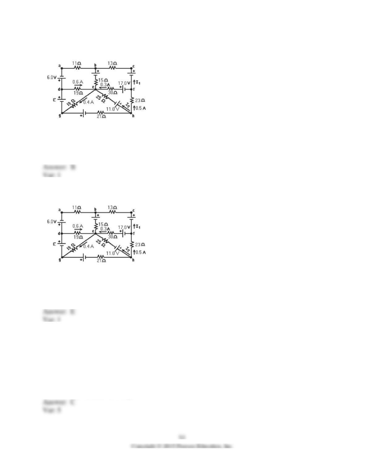
99) A multiloop circuit is shown in the figure, but some quantities are not labeled. Find the
current I1 if the batteries are ideal. (It is not necessary to solve the entire circuit.)
A) 0 A
B) +0.2 A
C) +0.4 A
D) -0.2 A
E) -0.4 A
100) A multiloop circuit is shown in the figure, but some quantities are not labeled. Find the
current I2 if the batteries are ideal. (It is not necessary to solve the entire circuit.)
A) +0.1 A
B) +0.3 A
C) +0.5 A
D) -0.1 A
E) -0.3 A
101) A 8.0-μF uncharged capacitor is connected in series with a 6.0–kΩ resistor, an ideal 20-V dc
source, and an open switch. If the switch is closed at time t = 0.0 s, what is the charge on the
capacitor at t = 9.0 ms?
A) 0 C
B) 37% of the minimum charge
C) 17% of the maximum charge
D) 68% of the minimum charge
E) 96% of the maximum charge
102) A 2.0-μF capacitor that is initially uncharged is charged through a 50–kΩ resistor. How
long does it take for the capacitor to reach 90% of its full charge?
A) 0.90 s
B) 0.23 s
C) 2.2 s
D) 2.3 s
103) A fully charged 37-µF capacitor is discharged through a 1.0-kΩ resistor. If the voltage
across the capacitor is reduced to 7.6 volts after just 20 ms, what was the original potential across
the capacitor?
A) 16 V
B) 13 V
C) 11 V
D) 9.0 V
E) 8.0 V
104) When an initially uncharged capacitor is charged through a 25-kΩ resistor by a 75-V dc
ideal power source, it takes 0.23 ms for the capacitor to reach 50% of its maximum charge?
What is the capacitance of this capacitor?
105) A 2.0-μF capacitor is charged to 12 V and then discharged through a 4.0–MΩ resistor. How
long will it take for the voltage across the capacitor to drop to 3.0 V?
A) 8.0 s
B) 11 s
C) 22 s
D) 24 s
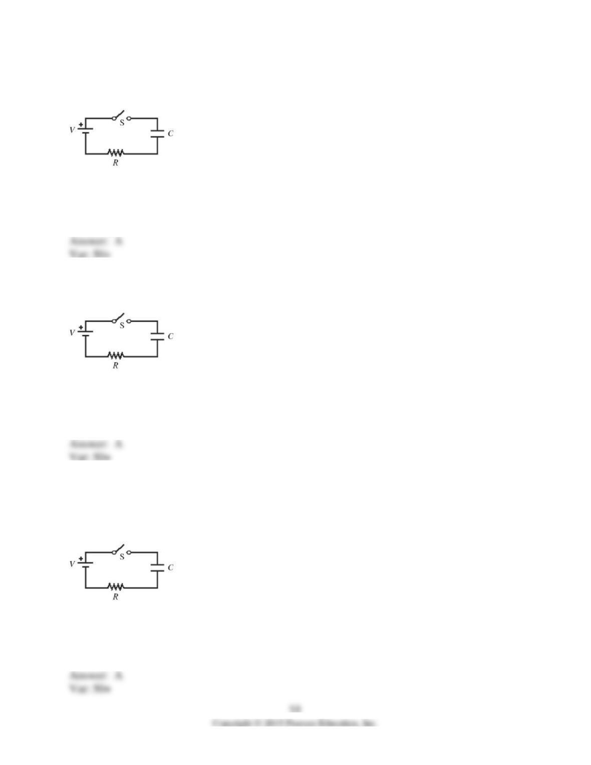
106) For the circuit shown in the figure, V = 60 V, C = 20 µF, R = 0.10 MΩ, and the battery is
ideal. Initially the switch S is open and the capacitor is uncharged. The switch is then closed at
time t = 0.00 s. What is the charge on the capacitor 8.0 s after closing the switch?
A) 1200 µC
B) 940 µC
C) 1400 µC
D) 1600 µC
E) 1900 µC
107) For the circuit shown in the figure, V = 20 V, C = 10 µF, R = 0.80 MΩ, and the battery is
ideal. Initially the switch S is open and the capacitor is uncharged. The switch is then closed at
time t = 0.00 s. What is the potential difference across the resistor 20 s after closing the switch?
A) 1.6 V
B) 2.0 V
C) 2.3 V
D) 2.6 V
E) 3.0 V
108) For the circuit shown in the figure, V = 60 V, C = 40 µF, R = 0.90 MΩ, and the battery is
ideal. Initially the switch S is open and the capacitor is uncharged. The switch is then closed at
time t = 0.00 s. At a given instant after closing the switch, the potential difference across the
capacitor is twice the potential difference across the resistor. At that instant, what is the charge
on the capacitor?
A) 1600 µC
B) 1400 µC
C) 1200 µC
D) 890 µC
E) 600 µC
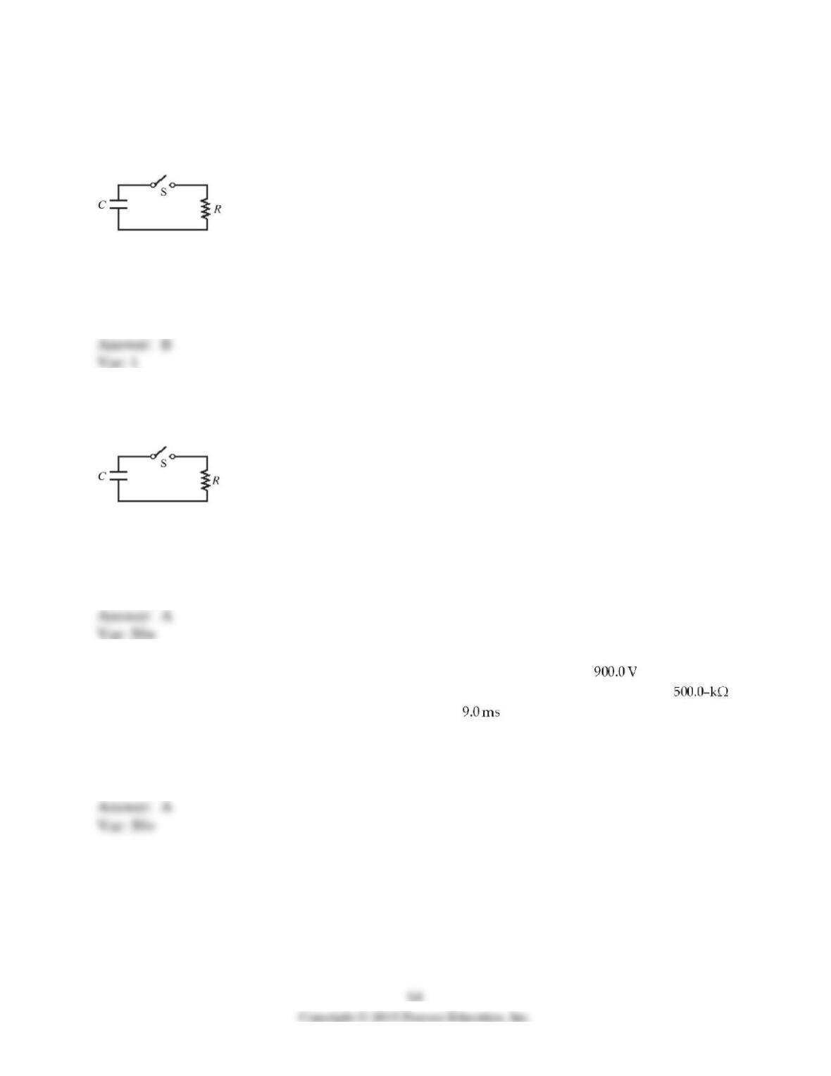
109) For the circuit shown in the figure, C = 12 µF and R = 8.5 MΩ. Initially the switch S is
open with the capacitor charged to a voltage of 80 V. The switch is then closed at time t = 0.00 s.
What is the charge on the capacitor, when the current in the circuit is 3.3 µA?
A) 350 µC
B) 340 µC
C) 480 µC
D) 620 µC
E) 700 µC
110) For the circuit shown in the figure, C = 13 µF and R = 7.6 MΩ. Initially the switch S is
open with the capacitor charged to a voltage of 80 V. The switch is then closed at time t = 0.00 s.
What is the charge on the capacitor 40 s after closing the switch?
A) 3300 µC
B) 3100 µC
C) 2900 µC
D) 2700 µC
E) 2500 µC
111) A 1.0-μF capacitor is charged until it acquires a potential difference of across its
plates, and then the emf source is removed. If the capacitor is then discharged through a
resistance, what is the voltage drop across the capacitor after beginning the discharge?
A) 880 V
B) 920 V
C) 16 V
D) -16 V
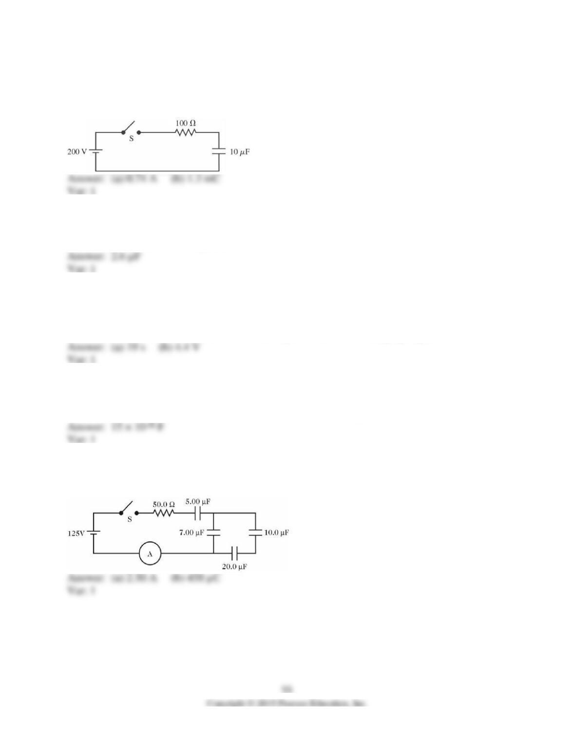
112) The capacitor shown in the circuit in the figure is initially uncharged when the switch S is
suddenly closed, and the battery is ideal. After one time constant has gone by, find (a) the current
through the resistor and (b) the charge on the capacitor. Assume that the numbers shown are all
accurate to two significant figures.
113) A circuit contains a 2.0-MΩ resistor in series with an uncharged capacitor. When this
combination is connected across an ideal battery, the capacitor reaches 25% of its maximum
charge in 1.5 s. What is its capacitance?
114) A series circuit consists of a 2.5-μF capacitor, a 7.6–MΩ resistor, and an ideal 6.0-V dc
power source.
(a) What is the time constant for charging the capacitor?
(b) What is the potential difference across the capacitor 25 s after charging begins?
115) A resistor with a resistance of 360 Ω is in a series circuit with a capacitor of capacitance 7.3
× 10-6 F. What capacitance must be placed in parallel with the original capacitance to change the
capacitive time constant of the combination to three times its original value?
116) In the circuit shown in the figure, all the capacitors are initially uncharged when the switch
S is suddenly closed, and the battery is ideal. Find (a) the maximum reading of the ammeter and
(b) the maximum charge on the 5.00-µF capacitor.