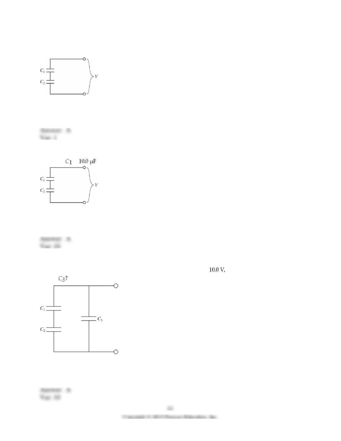
17) Two capacitors are connected as shown in the figure, with C1 = 4.0 µF and C2 = 7.0 µF. If a
voltage source V = 90 V is applied across the combination, find the potential difference across C1.
A) 57 V
B) 36 V
C) 60 V
D) 9.0 V
18) A potential difference of V = 100 V is applied across two capacitors in series, as shown in the
figure. If = and the voltage drop across it is 75 V, what is the capacitance of C2?
A) 30 μF
B) 2.5 μF
C) 7.5 μF
D) 3.3 μF
19) Three capacitors of equal capacitance are arranged as shown in the figure, with a voltage
source across the combination. If the voltage drop across C1 is what is the voltage drop
across
A) 20 V
B) 10.0 V
C) 40 V
D) 30 V
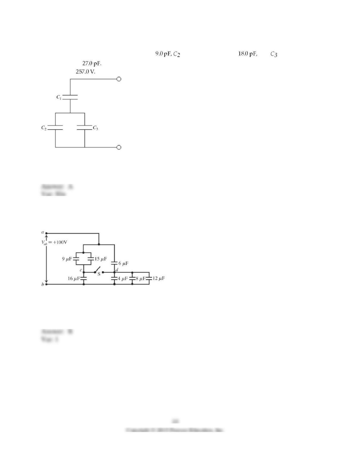
20) Three capacitors are arranged as shown in the figure, with a voltage source connected across
the combination. C1 has a capacitance of has a capacitance of and has a
capacitance of Find the potential drop across the entire arrangement if the potential drop
across C2 is
A) 1500 V
B) 1000 V
C) 470 V
D) 430 V
21) The capacitive network shown in the figure is assembled with initially uncharged capacitors.
Assume that all the quantities in the figure are accurate to two significant figures. The switch S
in the network is kept open throughout. What is the total energy stored in the seven capacitors?
A) 48 mJ
B) 72 mJ
C) 96 mJ
D) 120 mJ
E) 144 mJ
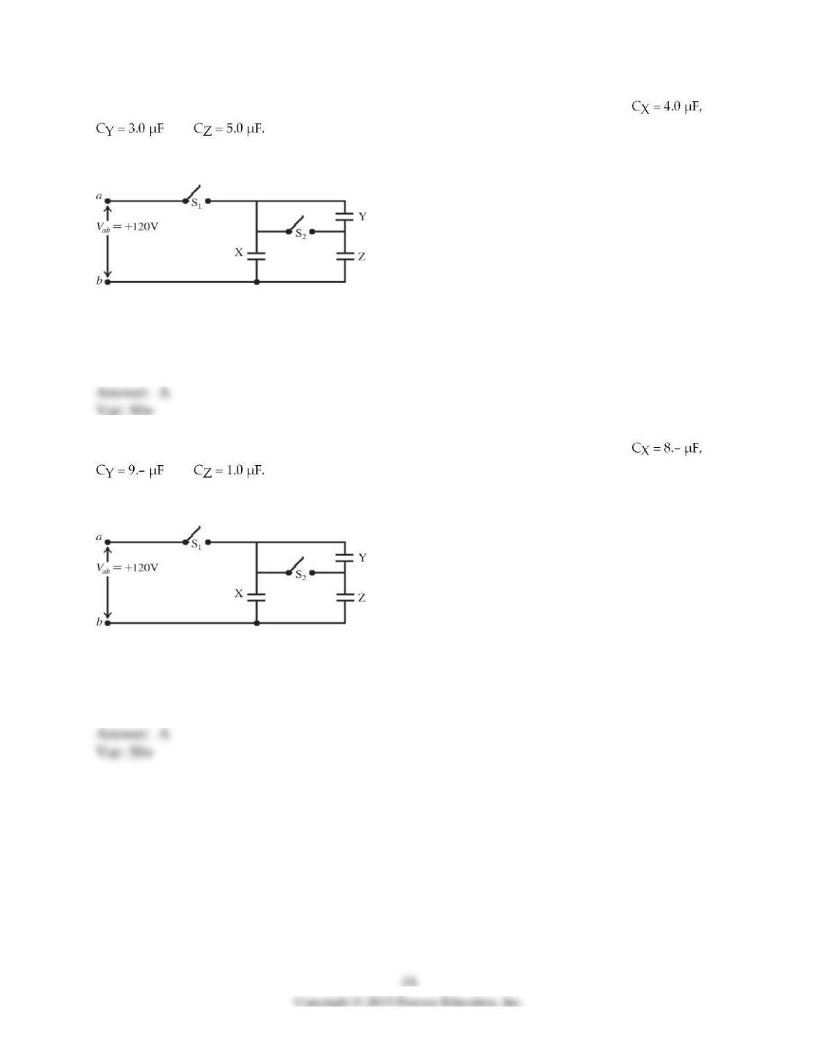
22) The network shown is assembled with uncharged capacitors X , Y, and Z, with
and The switches S1 and S2 are initially open, and a potential difference
Vab = 120 V is applied between points a and b. After the network is assembled, switch S1 is then
closed, but switch S2 is kept open. How much energy is finally stored in capacitor X?
A) 29 mJ
B) 0.48 mJ
C) 0.24 mJ
D) 58 mJ
E) 0.96 mJ
23) The network shown is assembled with uncharged capacitors X , Y, and Z, with
and The switches S1 and S2 are initially open, and a potential difference
Vab = 120 V is applied between points a and b. After the network is assembled, switch S1 is then
closed, but switch S2 is kept open. How much charge is finally stored in capacitor Y?
A) 110 µC
B) 54 µC
C) 81 µC
D) 140 µC
E) 160 µC
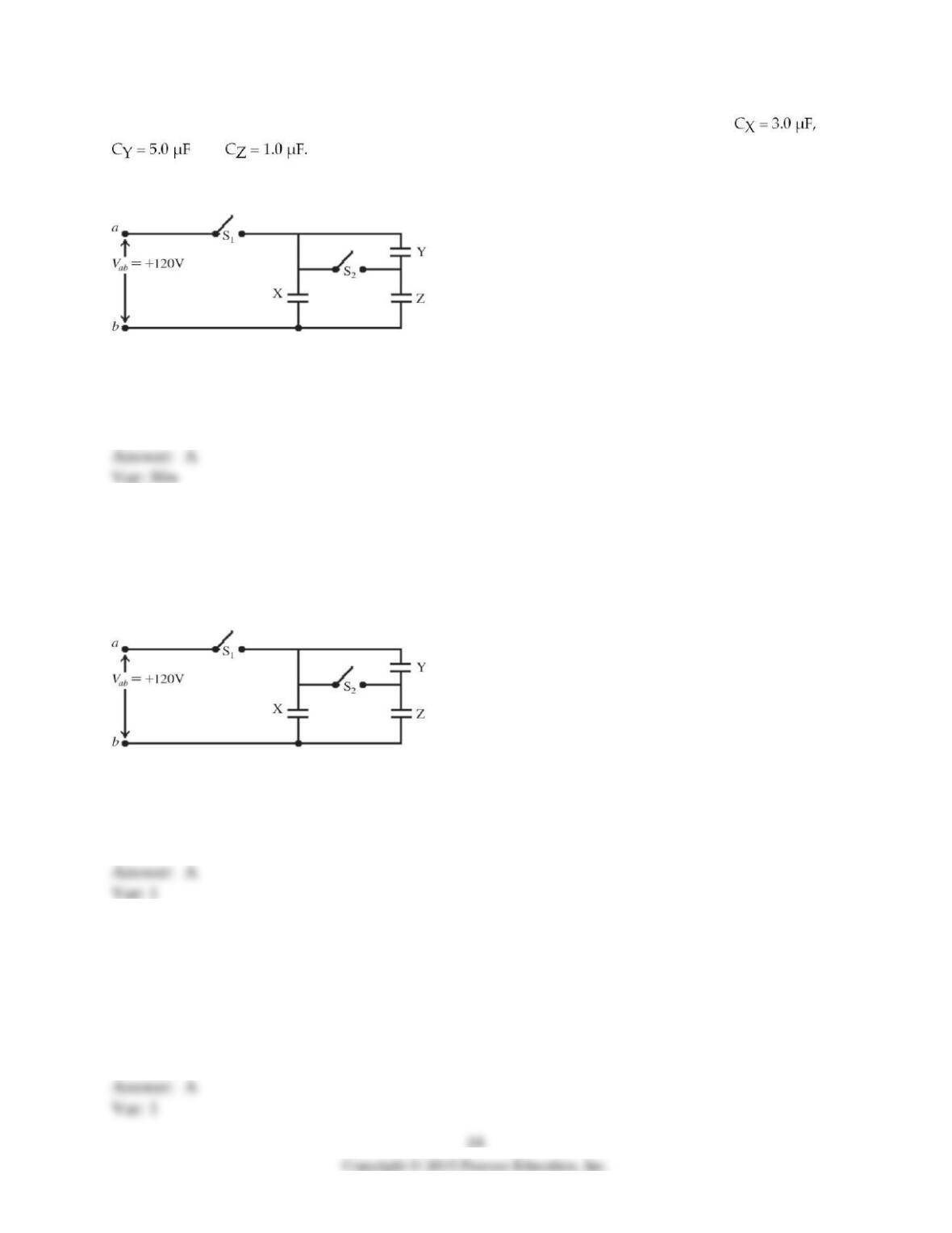
24) The network shown is assembled with uncharged capacitors X , Y, and Z, with
and The switches S1 and S2 are initially open, and a potential difference
Vab = 120 V is applied between points a and b. After the network is assembled, switch S1 is then
closed, but switch S2 is kept open. What is the final potential difference across capacitor Z?
A) 100 V
B) 600 V
C) 55 V
D) 38 V
E) 29 V
25) The network shown is assembled with uncharged capacitors X , Y, and Z, with CX = 4.0 μF,
CY = 6.0 μF, and CZ = 5.0 μF. The switches S1 and S2 are initially open, and a potential
difference Vab = 120 V is applied between points a and b. After the network is assembled,
switch S1 is then closed, but switch S2 is kept open. What is the final potential difference across
capacitor X?
A) 120 V
B) 82 V
C) 75 V
D) 67 V
E) 60 V
26) A group of 1.0-μF, 2.0–μF, and 3.0–μF capacitors is connected in parallel across a 24–V
potential difference (a battery). How much energy is stored in this three-capacitor combination
when the capacitors are fully charged?
A) 1.7 mJ
B) 2.1 mJ
C) 4.8 mJ
D) 7.1 mJ
27) A 9.00-µF and a 12.0-µF capacitor are connected together, and this combination is connected
across a 25.0-V potential difference. How much electric energy is stored in the combination if
they are connected (a) in parallel or (b) in series?
28) What different resistances can be obtained by using two 2.0-Ω resistors and one 4.0–Ω
resistor? You must use all three of them in each possible combination.
29) Two resistors in series are equivalent to 9.0 Ω, and in parallel they are equivalent to 2.0 Ω.
What are the resistances of these two resistors?
30) What resistance must be connected in parallel with a 633-Ω resistor to produce an equivalent
resistance of 205 Ω?
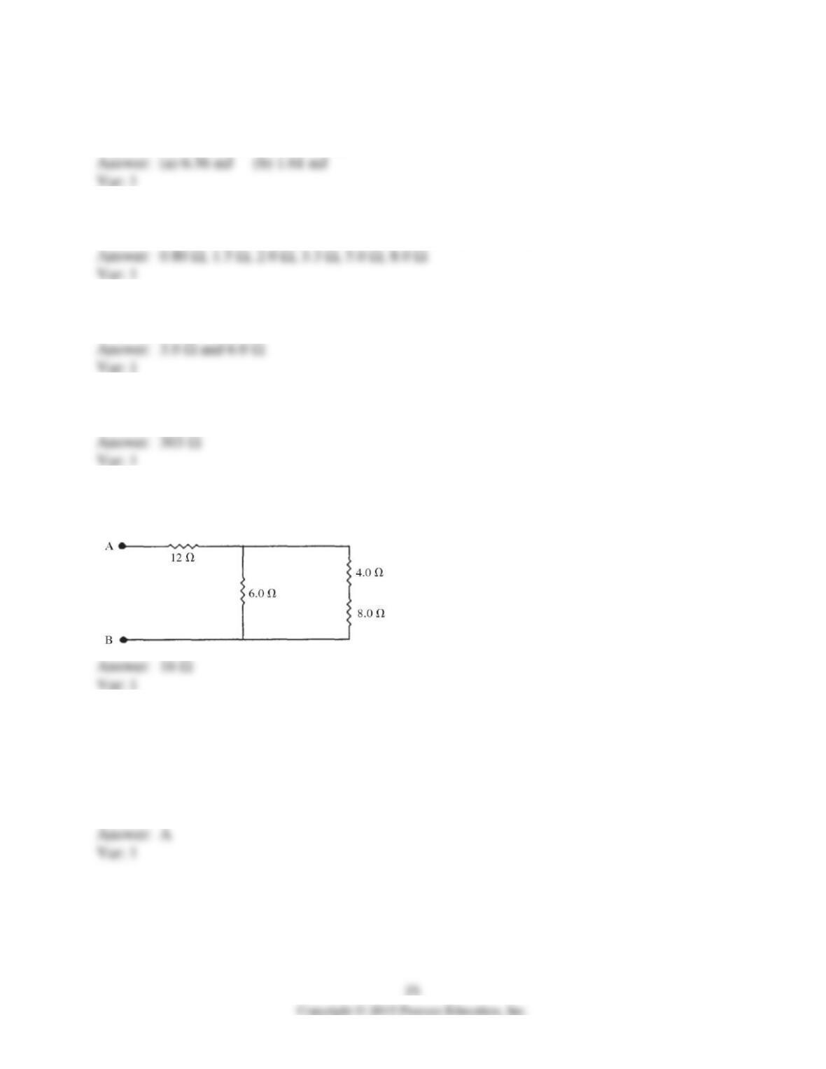
31) What is the equivalent resistance between points A and B of the network shown in the
figure?
32) A combination of a 2.0-Ω resistor in series with 4.0–Ω resistor is connected in parallel with a
3.0-Ω resistor. What is the equivalent resistance of this system?
A) 2.0 Ω
B) 3.0 Ω
C) 4.0 Ω
D) 9.0 Ω
33) Two 4.0-Ω resistors are connected in parallel, and this combination is connected in series
with 3.0 Ω. What is the equivalent resistance of this system?
A) 1.2 Ω
B) 5.0 Ω
C) 7.0 Ω
D) 11 Ω
34) A 2.0-Ω resistor is in series with a parallel combination of 4.0–Ω, 6.0–Ω, and 12–Ω resistors.
What is the equivalent resistance of this system?
A) 24 Ω
B) 4.0 Ω
C) 1.8 Ω
D) 2.7 Ω
35) What is the equivalent resistance in the circuit shown in the figure?
A) 80 Ω
B) 55 Ω
C) 50 Ω
D) 35 Ω
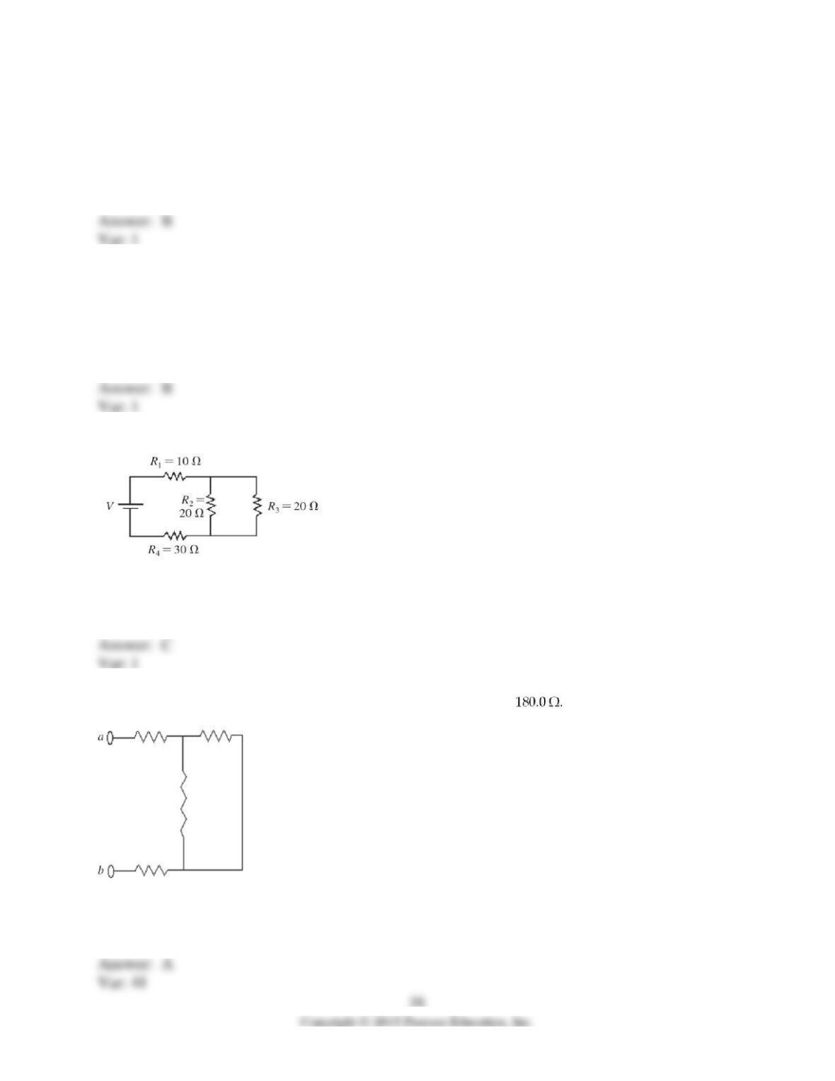
36) Each of the resistors shown in the figure has a resistance of What is the equivalent
resistance between points a and b of this combination?
A) 450.0 Ω
B) 720.0 Ω
C) 540.0 Ω
D) 180.0 Ω
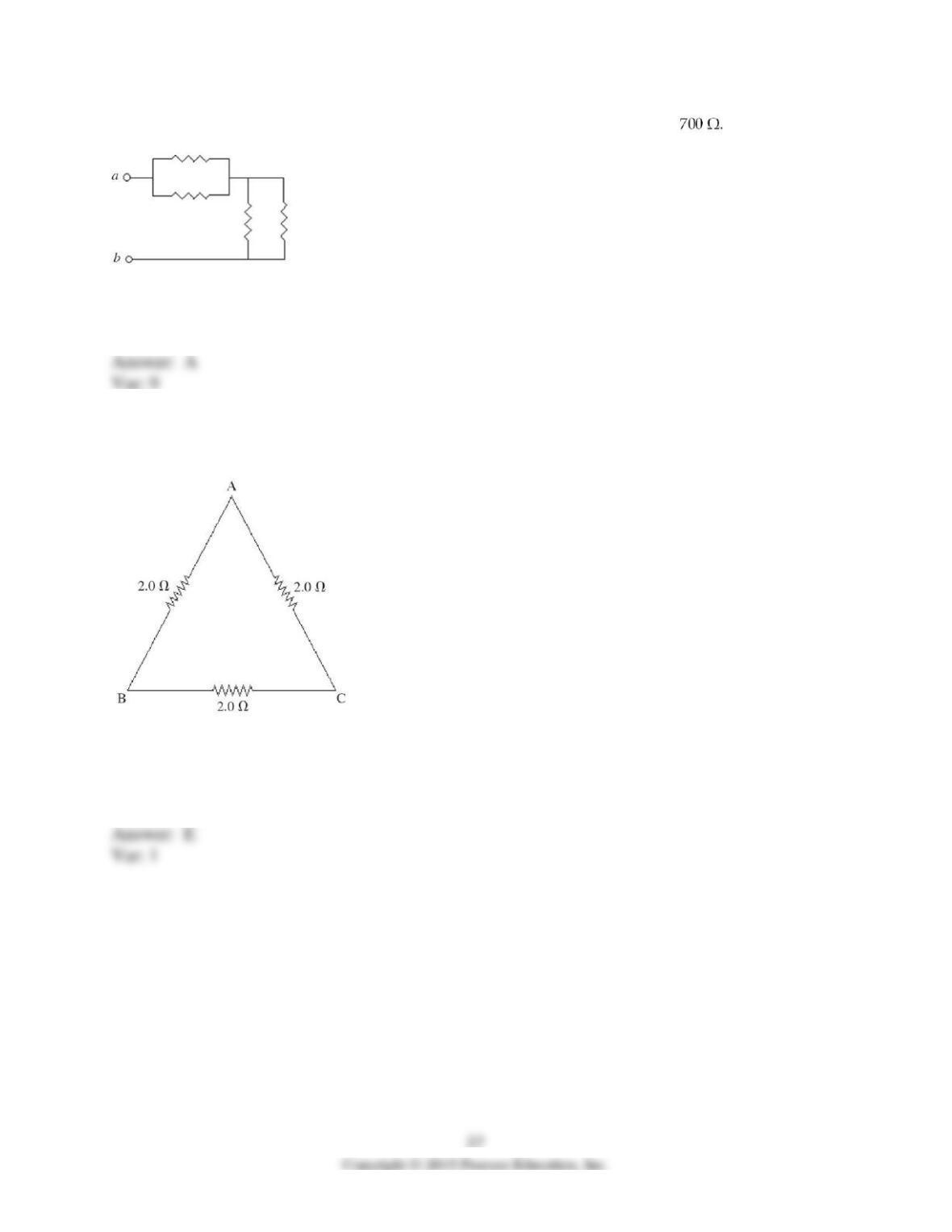
37) The resistors in the circuit shown in the figure each have a resistance of What is the
equivalent resistance between points a and b of this combination?
A) 700 Ω
B) 2800 Ω
C) 175 Ω
D) 1400 Ω
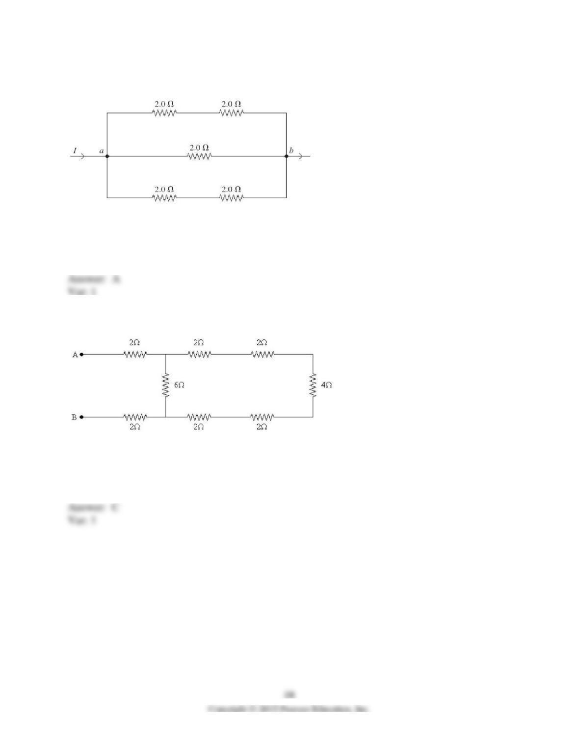
38) Three 2.0-Ω resistors are connected to form the sides of an equilateral triangle ABC as
shown in the figure. What is the equivalent resistance between any two points, AB, BC, or AC,
of this circuit?
A) 2.0 Ω
B) 6.0 Ω
C) 4.3 Ω
D) 3.3 Ω
E) 1.3 Ω
39) Five 2.0-Ω resistors are connected as shown in the figure. What is the equivalent resistance
of this combination between points a and b?
A) 1.0 Ω
B) 10.0 Ω
C) 2.0 Ω
D) 6.0 Ω
E) 0.40 Ω
40) A number of resistors are connected across points A and B as shown in the figure. What is
the equivalent resistance between points A and B?
A) 4 Ω
B) 6 Ω
C) 8 Ω
D) 10 Ω
E) 12 Ω
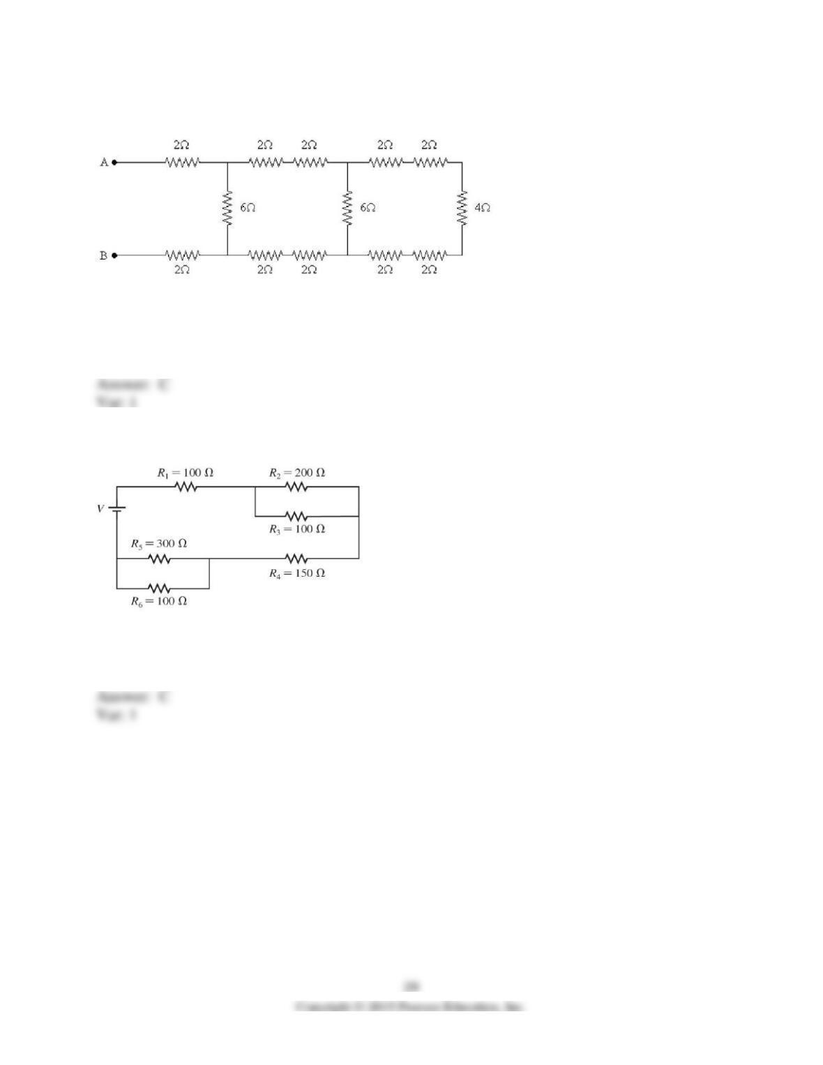
41) A number of resistors are connected across points A and B as shown in the figure. What is
the equivalent resistance between points A and B?
A) 4 Ω
B) 6 Ω
C) 8 Ω
D) 10 Ω
E) 12 Ω
42) What is the equivalent resistance of the circuit shown in the figure? The battery is ideal and
all resistances are accurate to 3 significant figures.
A) 950 Ω
B) 450 Ω
C) 392 Ω
D) 257 Ω
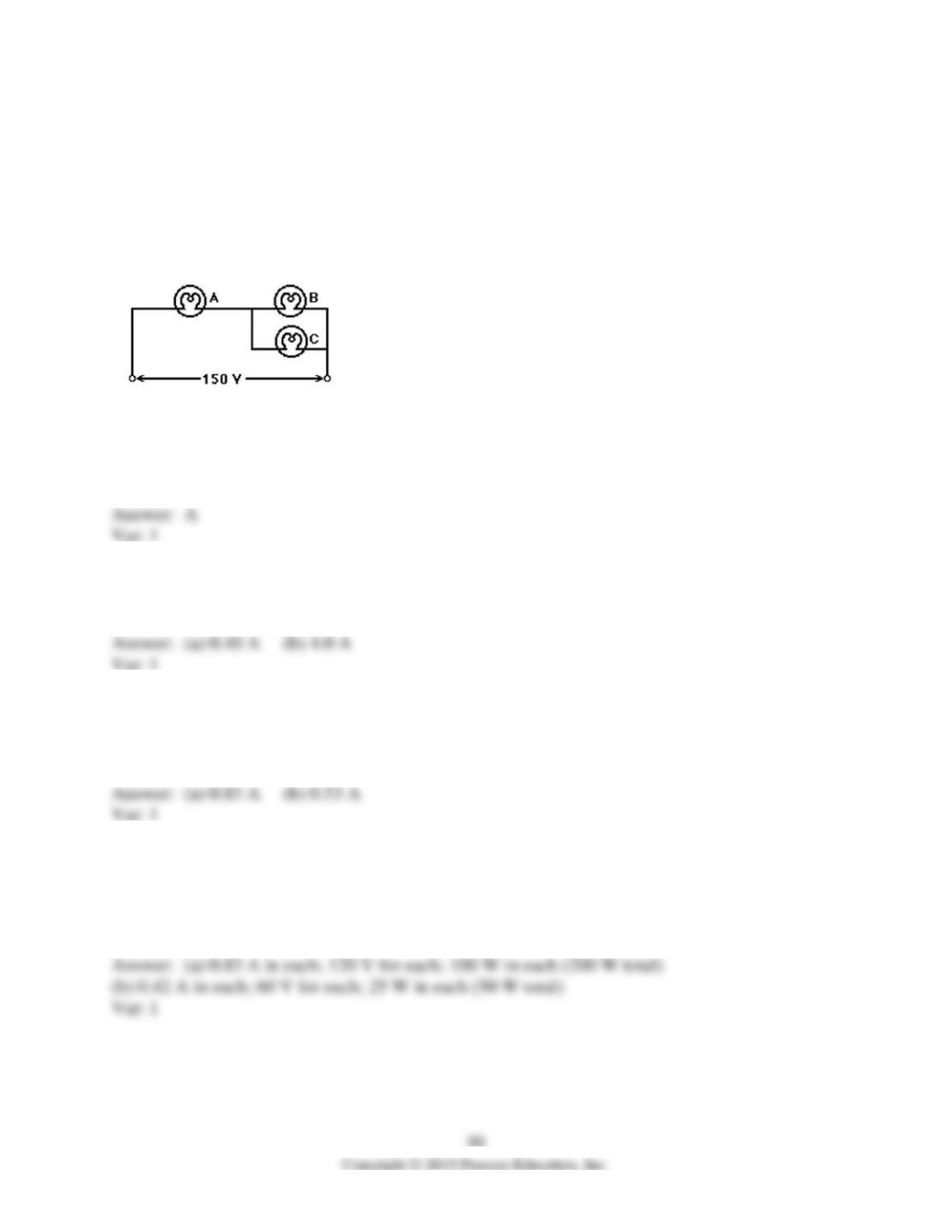
43) Three light bulbs, A, B, and C, have electrical ratings as follows:
Bulb A: 96.0 W, 1.70 A
Bulb B: 80.0 V, 205 W
Bulb C: 120 V, 0.400 A
These three bulbs are connected in a circuit across a 150-V voltage power source, as shown in
the figure. Assume that the filament resistances of the light bulbs are constant and independent of
operating conditions. What is the equivalent resistance of this combination of bulbs between the
terminals of the power source?
A) 61.5 Ω
B) 15.3 Ω
C) 74.0 Ω
D) 86.2 Ω
E) 364 Ω
44) Three resistors of 12 Ω, 12 Ω, and 6.0 Ω are connected together, and an ideal 12-V battery is
connected across the combination. What is the current from the battery if they are connected (a)
in series or (b) in parallel?
45) Two resistors with resistances of 5.0 Ω and 9.0 Ω are connected in parallel. A 4.0–Ω resistor
is then connected in series with this parallel combination. An ideal 6.0-V battery is then
connected across the series-parallel combination. What is the current through (a) the 4.0-Ω
resistor and (b) the 5.0-Ω resistor?
46) Two 100-W light bulbs of fixed resistance are to be connected to an ideal 120-V source.
What are the current, potential difference, and dissipated power for each bulb when they are
connected
(a) in parallel (the normal arrangement)?
(b) in series?
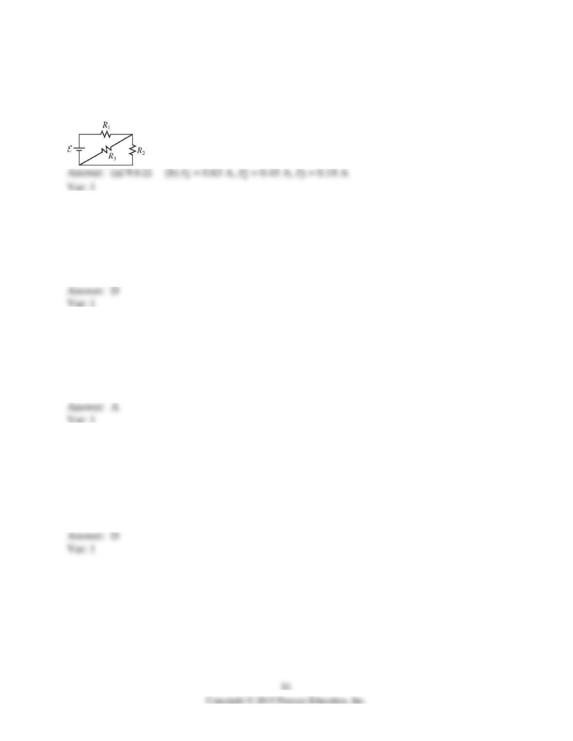
47) For the circuit shown in the figure, R1 = 5.6 Ω, R2 = 5.6 Ω, R3 = 14 Ω, and ε = 6.0 V, and
the battery is ideal.
(a) What is the equivalent resistance across the battery?
(b) Find the current through each resistor.
48) A 22-A current flows into a parallel combination of 4.0-Ω, 6.0–Ω, and 12–Ω resistors. What
current flows through the 12-Ω resistor?
A) 18 A
B) 11 A
C) 7.3 A
D) 3.7 A
49) A 6.0-Ω and a 12–Ω resistor are connected in parallel across an ideal 36-V battery. What
power is dissipated by the 6.0-Ω resistor?
A) 220 W
B) 48 W
C) 490 W
D) 24 W
50) The following three appliances are connected in parallel across an ideal 120-V dc power
source: 1200-W toaster, 650-W coffee pot, and 600-W microwave. If all were operated at the
same time what total current would they draw from the source?
A) 4.0 A
B) 5.0 A
C) 10 A
D) 20 A
51) A certain 20-A circuit breaker trips when the current in it equals 20 A. What is the maximum
number of 100-W light bulbs you can connect in parallel in an ideal 120-V dc circuit without
tripping this circuit breaker?
A) 11
B) 17
C) 23
D) 27
52) A15-Ω resistor is connected in parallel with a 30–Ω resistor. If this combination is now
connected in series with an ideal 9.0-V battery and a 20-Ω resistor, what is the current through
the 15-Ω resistor?
A) 0.10 A
B) 0.13 A
C) 0.20 A
D) 0.26 A
53) Three resistors of resistances 4.0 Ω, 6.0 Ω, and 10 Ω are connected in parallel. If this
combination is now connected in series with an ideal 12-V battery and a 2.0-Ω resistor, what is
the current through the 10-Ω resistor?
A) 0.59 A
B) 2.7 A
C) 11 A
D) 16 A
54) Two resistors having resistances of 5.0 Ω and 9.0 Ω are connected in parallel. A 4.0–Ω
resistor is then connected in series with the parallel combination. An ideal 6.0-V battery is then
connected across the series-parallel combination. What is the current through the 9.0-Ω resistor?
A) 0.35 A
B) 0.53 A
C) 0.83 A
D) 0.30 A
E) 0.67 A
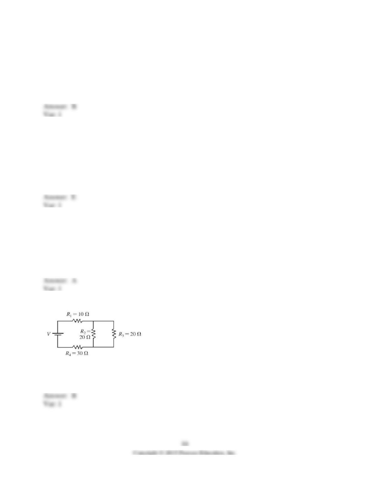
55) A 3.0-Ω resistor is connected in parallel with a 6.0–Ω resistor. This combination is then
connected in series with a 4.0-Ω resistor. The resistors are connected across an ideal 12-volt
battery. How much power is dissipated in the 3.0-Ω resistor?
A) 2.7 W
B) 5.3 W
C) 6.0 W
D) 12 W
56) Four resistors having resistances of 20 Ω, 40 Ω, 60 Ω, and 80 Ω are connected in series
across an ideal dc voltage source. If the current through this circuit is 0.50 A, what is the voltage
of the voltage source?
A) 20 V
B) 40 V
C) 60 V
D) 80 V
E) 100 V
57) Four resistors having resistances of 20 Ω, 40 Ω, 60 Ω, and 80 Ω are connected in series
across an ideal 50-V dc source. What is the current through each resistor?
A) 0.25 A
B) 0.50 A
C) 0.75 A
D) 2.0 A
E) 4.0 A
58) If V = 40 V and the battery is ideal, what is the potential difference across R1 in the figure?
A) 6.7 V
B) 8.0 V
C) 10 V
D) 20 V
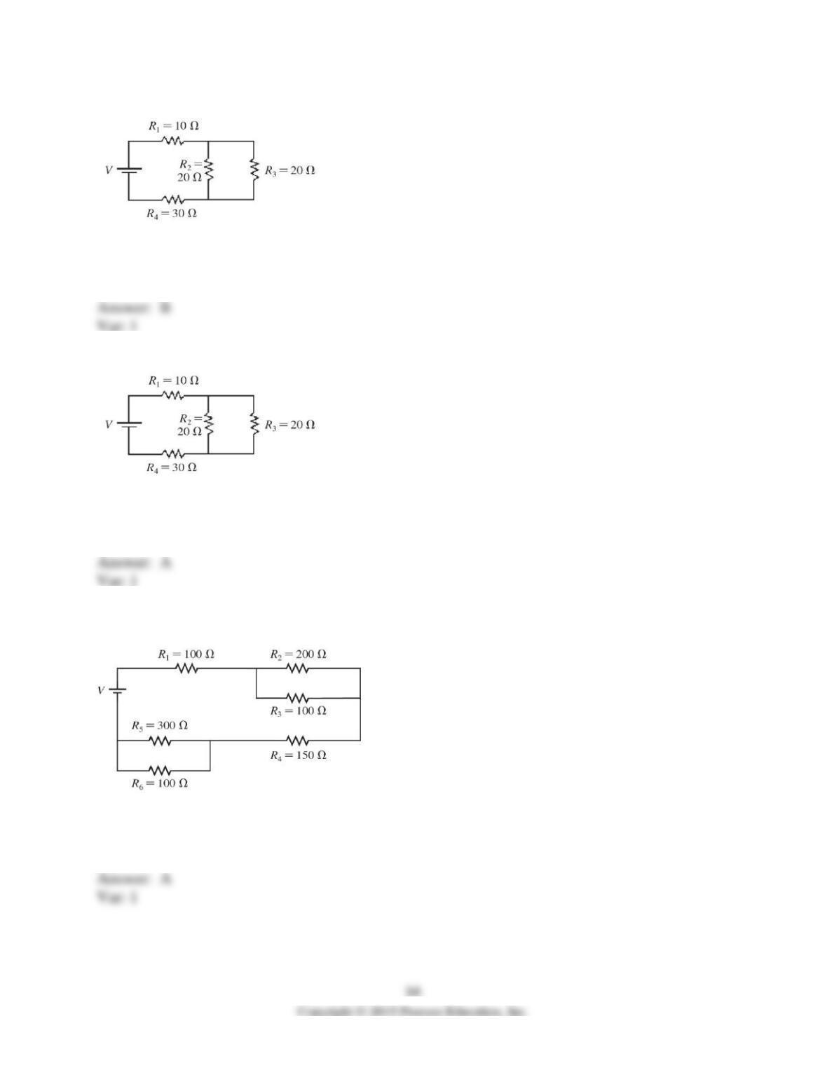
59) If V = 20 V and the battery is ideal, what is the current through R3 in the figure?
A) 0.050 A
B) 0.20 A
C) 1.0 A
D) 4.0 A
60) If 1.5 A flows through R2, what is the emf V of the ideal battery in the figure?
A) 150 V
B) 75 V
C) 60 V
D) 30 V
61) If emf of the ideal battery is V = 100 V, what is the potential difference across R5 for the
circuit shown in the figure?
A) 19 V
B) 40 V
C) 75 V
D) 77 V
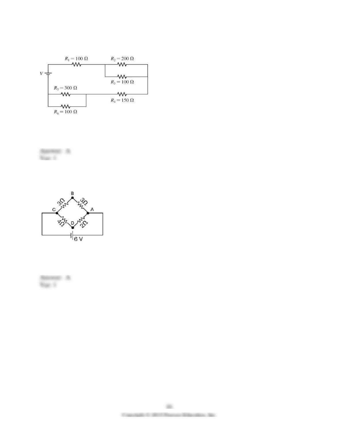
62) If emf of the ideal battery is V = 4.0 V, what is the current through R6 for the circuit shown
in the figure?
A) 0.0077 A
B) 0.017 A
C) 0.040 A
D) 4.0 A
63) What is the magnitude of the potential difference between points A and C for the circuit
shown in the figure? The battery is ideal, and all the numbers are accurate to two significant
figures.
A) 6.0 V
B) 4.0 V
C) 3.0 V
D) 2.0 V
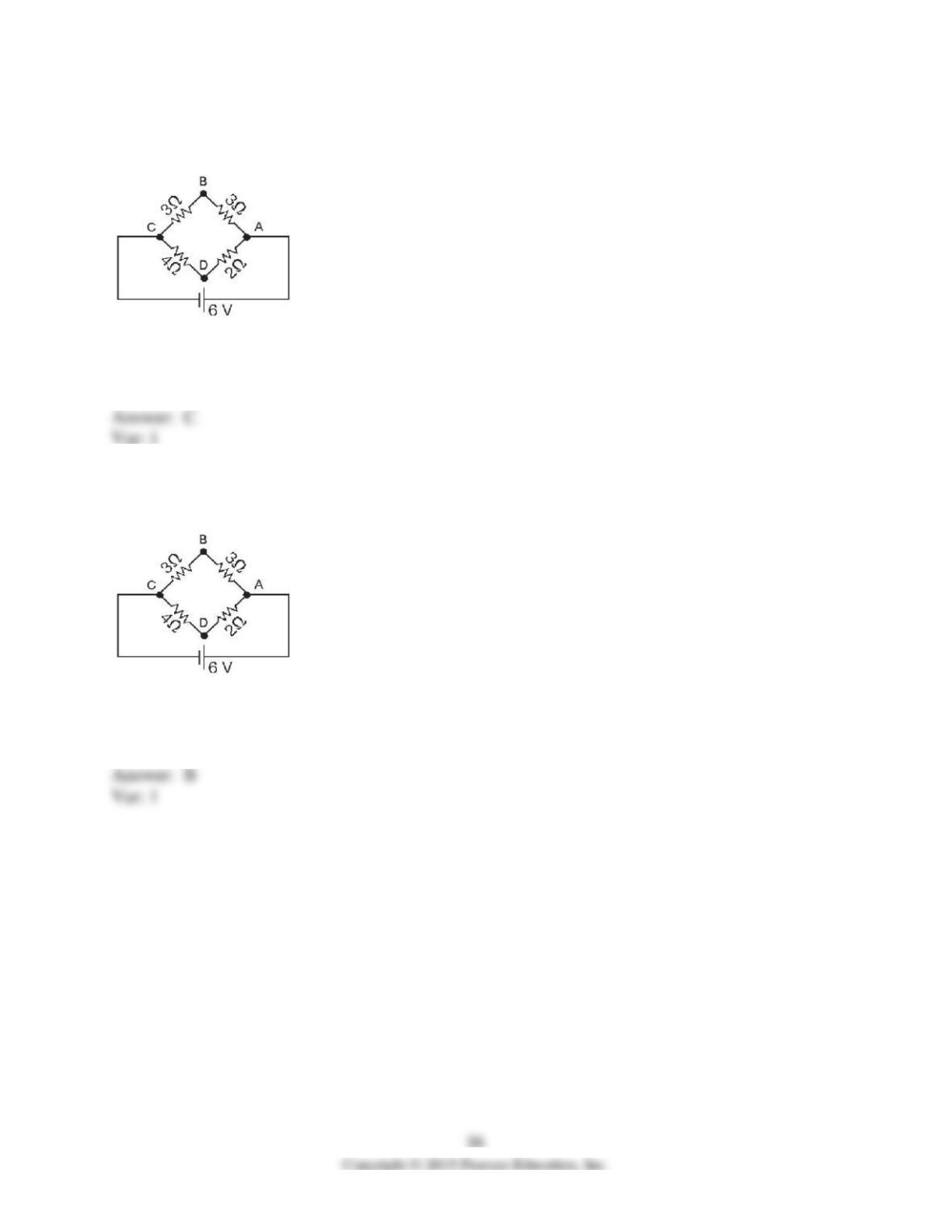
64) What is the magnitude of the potential difference between points B and C for the circuit
shown in the figure? The battery is ideal, and all the numbers are accurate to two significant
figures.
A) 6.0 V
B) 4.0 V
C) 3.0 V
D) 2.0 V
65) What is the magnitude of the potential difference between points C and D for the circuit
shown in the figure? The battery is ideal, and all the numbers are accurate to two significant
figures.
A) 6.0 V
B) 4.0 V
C) 3.0 V
D) 2.0 V
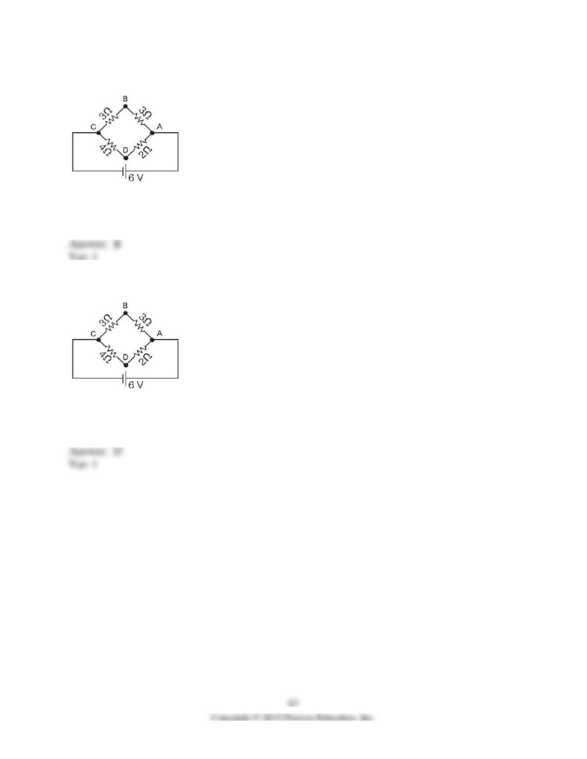
66) What current flows from the battery in the circuit shown in the figure? The battery is ideal,
and all the numbers are accurate to two significant figures.
A) 0.35 A
B) 2.0 A
C) 2.5 A
D) 3.0 A
67) What is the potential drop from point A to point B for the circuit shown in the figure? The
battery is ideal, and all the numbers are accurate to two significant figures.
A) 0.35 V
B) 2.0 V
C) 2.5 V
D) 3.0 V
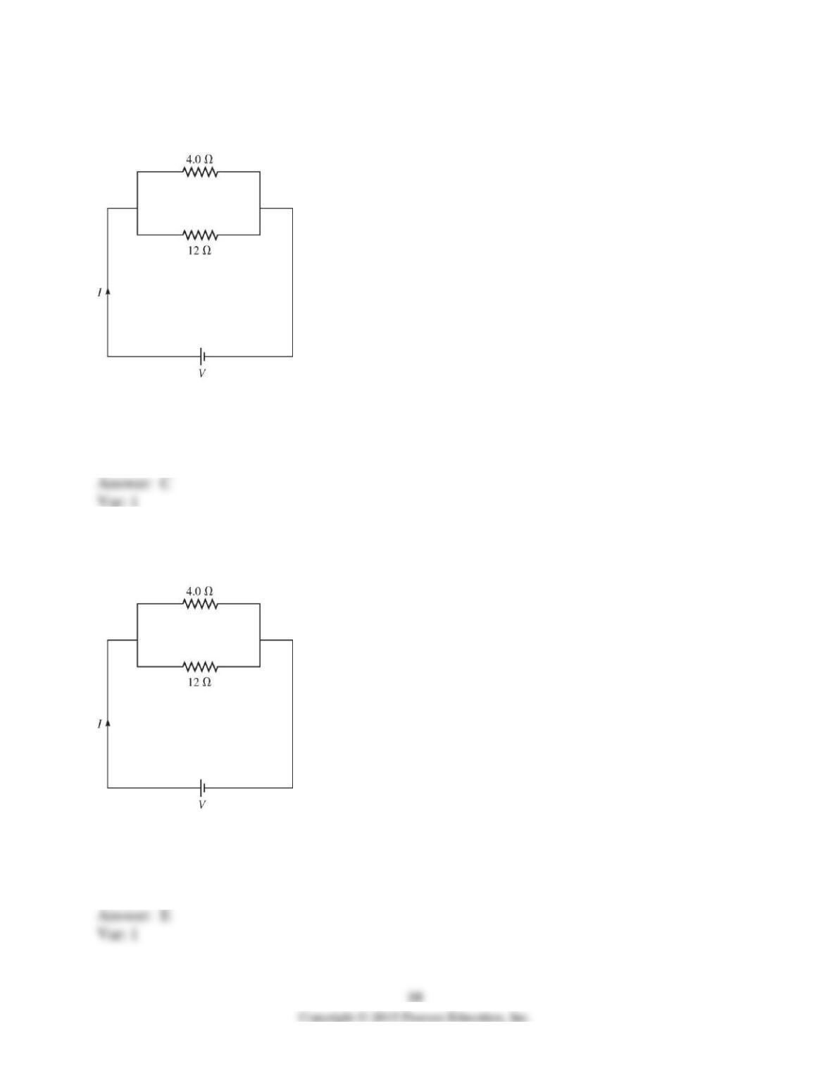
68) A 4.0-Ω resistor is connected to a 12–Ω resistor and this combination is connected to an ideal
dc power supply with voltage V as shown in the figure. If the total current in this circuit is I = 2.0
A, what is the value of voltage V?
A) 2.0 V
B) 3.0 V
C) 6.0 V
D) 1.5 V
E) 8.0 V
69) A 4.0-Ω resistor is connected with a 12–Ω resistor and both of these are connected across an
ideal dc power supply with voltage V as shown in the figure. If the total current in this circuit is I
= 2.0 A, what is the current through the 4.0-Ω resistor?
A) 2.0 A
B) 2.5 A
C) 0.5 A
D) 3.0 A
E) 1.5 A