Exam
Name___________________________________
MULTIPLE CHOICE. Choose the one alternative that best completes the statement or answers the question.
1)
Abridge is balanced when
1)
A)
the ratios of appropriate resistances are not equal.
B)
there is a voltage drop across the bridge arm of the circuit.
C)
the ratios of appropriate resistances are equal.
D)
anon–zero current flows through the bridge arm.
2)
When using the general nodal analysis approach, you must write
2)
A)
KCL at each non–trivial node (except the reference node) in terms of the branch currents.
B)
KCL at each non–trivial node (except the reference node) in terms of the mesh currents.
C)
KCL at each non–trivial node including the reference node in terms of the branch currents.
D)
KVL at each non–trivial node in terms of the branch currents.
3)
When doing delta–to–wye conversions
3)
A)
the delta–wye conversion equations for AC circuits are different than those used for the DC
delta–wye conversion equations even if impedances are used instead of resistances.
B)
if the resistances are equal in one configuration, then they are unequal in the other
configuration.
C)
if the resistances are equal in one configuration, then they are equal in the other configuration.
D)
All of the above
4)
The general nodal analysis approach usually requires that you
4)
A)
identify and label all nodes, including trivial nodes.
B)
assign the reference node to the node with the greatest number of connections.
C)
identify areference node.
D)
Both Aand B
5)
The general mesh analysis approach requires that you
5)
A)
write KCL for each mesh.
B)
assign one mesh current to each branch.
C)
assign the same mesh current (including direction) to every mesh.
D)
assign only one voltage polarity across each passive component.
6)
In the nodal analysis technique, once you have solved the simultaneous node voltage equations,
you can determine other voltages and the branch currents from the
6)
A)
node voltages.
B)
branch currents.
C)
mesh currents.
D)
component voltages.
7)
Analysis techniques other than superposition are needed because
7)
A)
superposition is not practically usable when there is alarge number of sources.
B)
the standard procedures of mesh and nodal analysis make these techniques usable for circuit
simulation software.
C)
mesh and nodal analysis techniques have standard procedures that are applicable to all
circuits.
D)
All of the above
8)
Adelta configuration of resistances (or impedances) is connected in a(n)
8)
A)
“Y”
B)
“X”
C)
“T”
D)
triangle
9)
The solution to the mesh equations for acircuit can be used to determine
9)
A)
the mesh currents from the branch currents.
B)
the branch currents from the mesh currents.
C)
all mesh voltages from the mesh currents.
D)
None of the above
10)
Abridge circuit hasaresistance (or impedance) across two points in the circuit that makes
10)
A)
laboratory circuit measurements impossible.
B)
mesh circuit analysis unusable.
C)
nodal circuit analysis unusable.
D)
series–parallel circuit analysis unusable.
11)
When using the general mesh analysis approach you
11)
A)
solve the simultaneous KVL equationsfor the mesh currents.
B)
need not express the voltage across each component.
C)
substitute mesh currents into the KCL equations.
D)
express each mesh current in terms of the branch current(s).
12)
In the nodal analysis technique, once you have substituted the branch current expressions into the
KCL node equations, you must solve the simultaneous equations for the
12)
A)
component voltages.
B)
node voltages.
C)
branch currents.
D)
mesh currents.
13)
In the nodal analysis technique, you must
13)
A)
use superposition where necessary to assist in this process.
B)
for those branches with acurrent source, the value of the branch current equals the node
voltage.
C)
express each branch current, including branches with current sources, in terms of adjacent
non–trivial node voltages.
D)
express each branch current (except branches with current sources) in terms of adjacent
non–trivial node voltages.
14)
Delta–wye conversions are useful in the analysis of
14)
A)
bridge circuits.
B)
some complicated series–parallel circuits.
C)
Both Aand B
D)
None of the above
15)
Awye configuration of resistances (or impedances) is connected in a(n)
15)
A)
“T”
B)
“V”
C)
triangle
D)
“X”
16)
When using the general nodal analysis approach
16)
A)
the current direction is arbitrary in abranch that includes acurrent source.
B)
you usually need not indicate branch currents or the current direction.
C)
for abranch that is connected to the reference node and consists only of passive components
(R, L, and/or C), the current must be assigned to flow toward the reference node.
D)
the current direction in each branch is always arbitrary.
SHORT ANSWER. Write the word or phrase that best completes each statement or answers the question.
17)
Adelta ()configuration of resistances has the following resistance values: RA = 100 , RB
= 100,and RC = 100.The values for each of the resistances in the wye (Y) configuration
are ________.
17)
18)
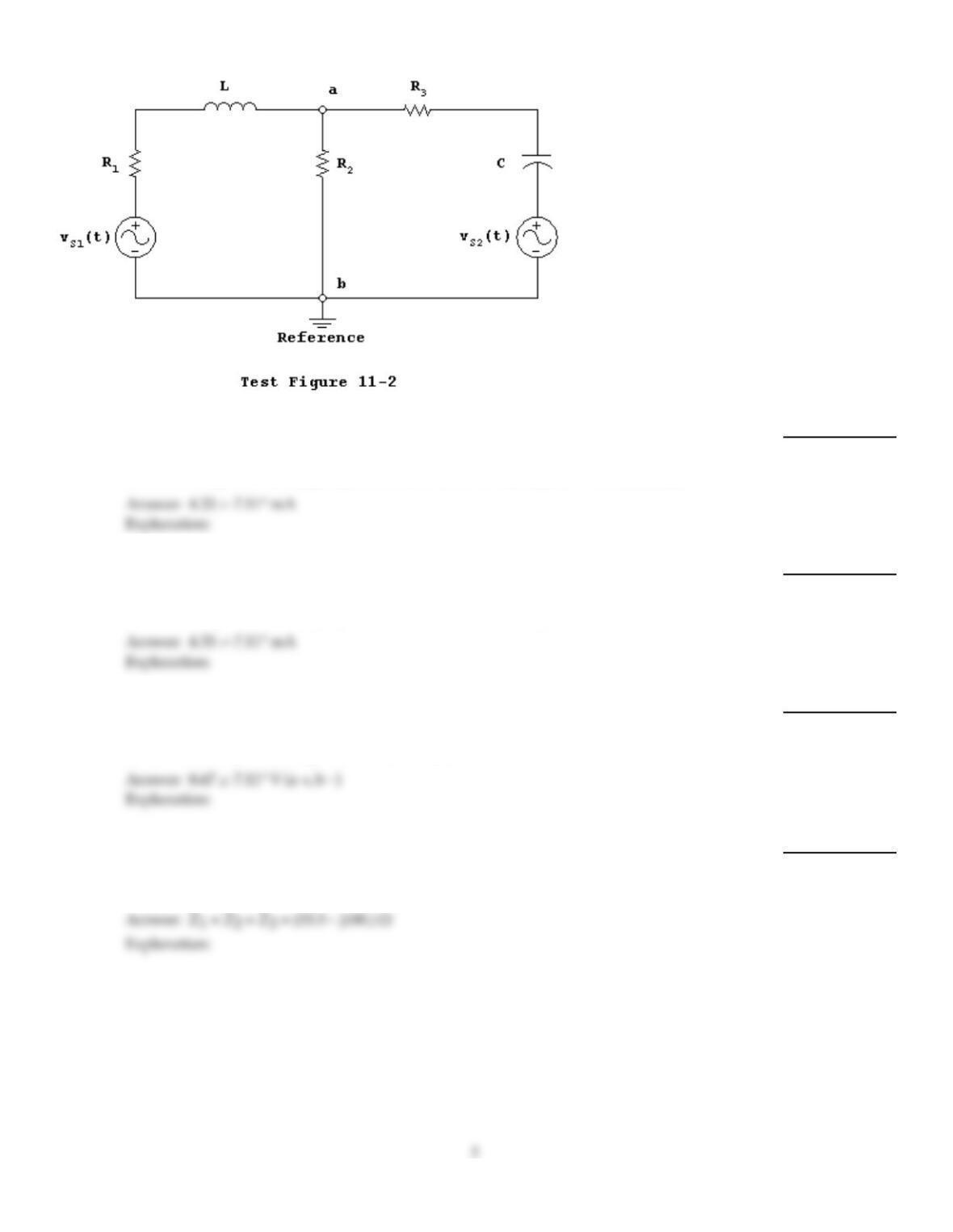
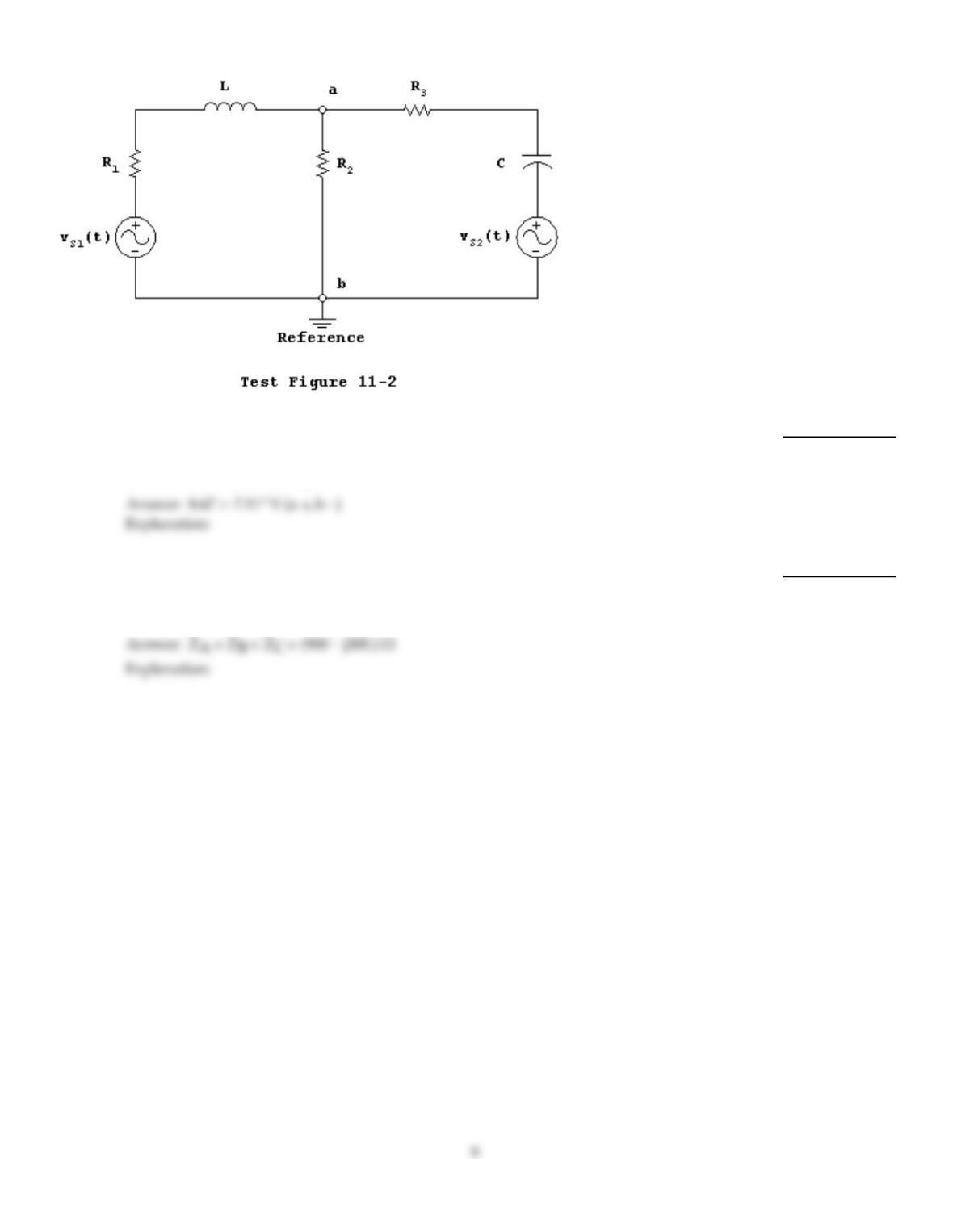
Assume that vS1(t) = 35.355sin(1000t), vS2(t) = 70.711sin(1000t + 45°),R1 = 1.0 k, R2 = 2.0
k, R3 = 2.0 k, XL = 1.0 k,and XC = 5.0 k.Using nodal analysis, the RMS branch
current through resistor R2going toward terminal bin Test Figure 11–2is ________.
18)
19)
Assume that vS1(t) = 35.355sin(1000t), vS2(t) = 70.711sin(1000t + 45°),R1 = 1.0 k, R2 = 2.0
k, R3 = 2.0 k, XL = 1.0 k,and XC = 5.0 k.Using mesh analysis, the RMS branch
current through resistor R2going toward terminal bin Test Figure 11–2is ________.
19)
20)
Assume that vS1(t) = 35.355sin(1000t), vS2(t) = 70.711sin(1000t + 45°),R1 = 1.0 k, R2 = 2.0
k, R3 = 2.0 k, XL = 1.0 k,and XC = 5.0 k.Using mesh analysis, the RMS voltage
across resistor R2in Test Figure 11–2is ________.
20)
21)
~
~ ~
Adelta ()configuration of impedance has the following impedance values: A = (100 –
j300) ,B = (100 – j300) ,and C = (100 – j300) .The values for each of the impedance
in the wye (Y) configuration are ________.
21)
22)
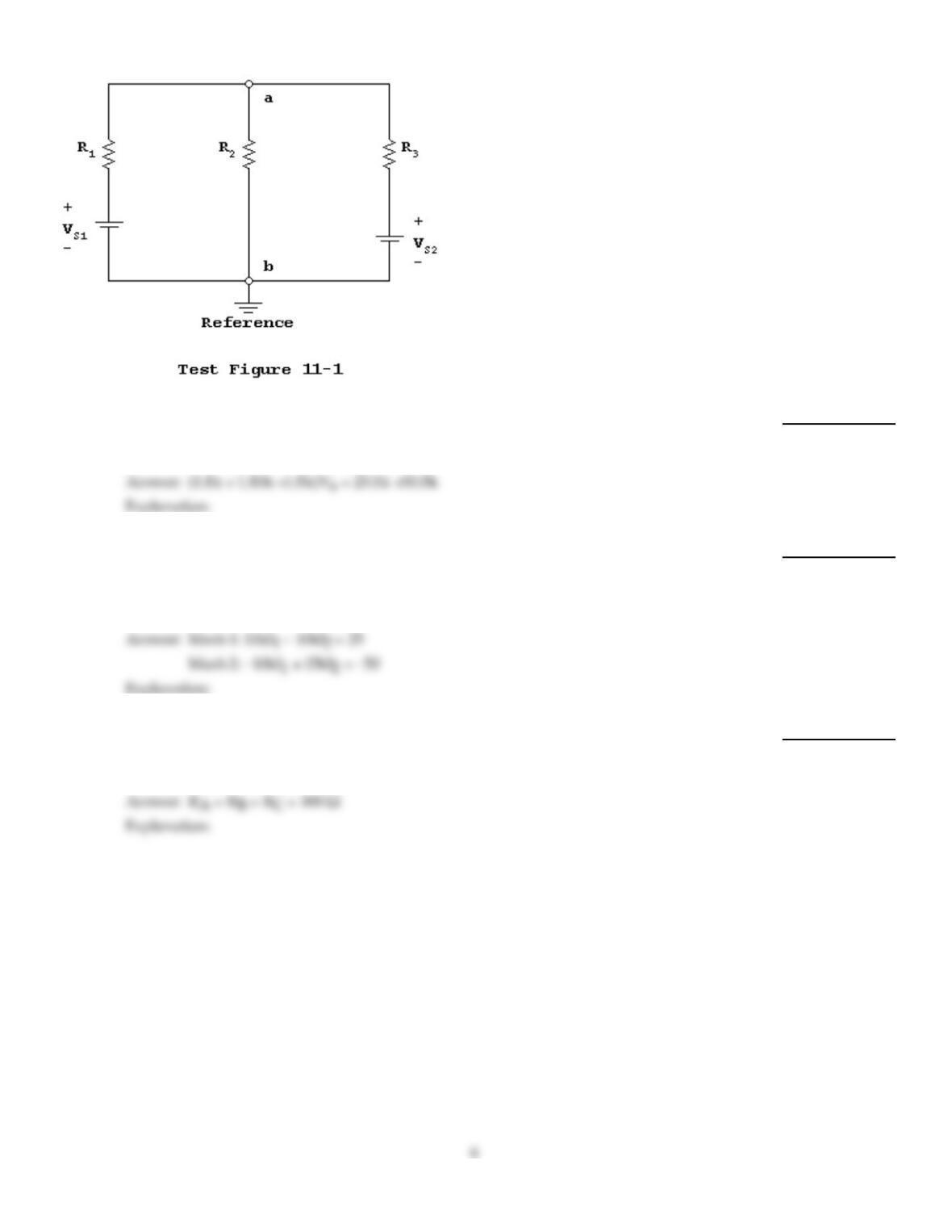
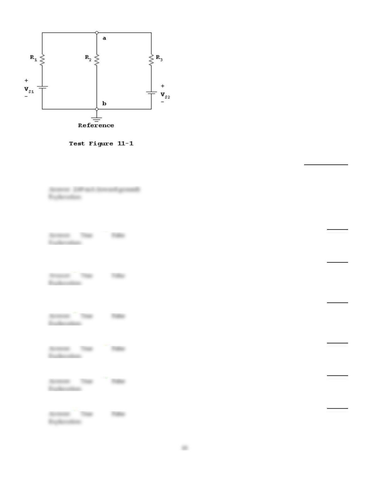
Assume that VS1 = 25 VDC, VS2 = 50 VDC, R1 = 1.0 k, R2 = 10.0 k,and R3 = 5.0 k.
Assume that the reference node for the circuit in Test Figure 11–1is as shown. The
equation(s) needed to solve for the node voltage(s) is (are) ________.
22)
23)
Assume that VS1 = 25 VDC, VS2 = 50 VDC, R1 = 1.0 k, R2 = 10.0 k,and R3 = 5.0 k.For
Test Figure 11–1, assume that the mesh current(s) are defined in the clockwise direction
with I1in the left mesh. The equation(s) needed to solve for the mesh current(s) is (are)
________.
23)
24)
Awye (Y) configuration of resistances hasthe following resistance values: R1 = 100, R2 =
100,and R3 = 100.The values for each of the resistances in the delta ()configuration
are ________.
24)
25)
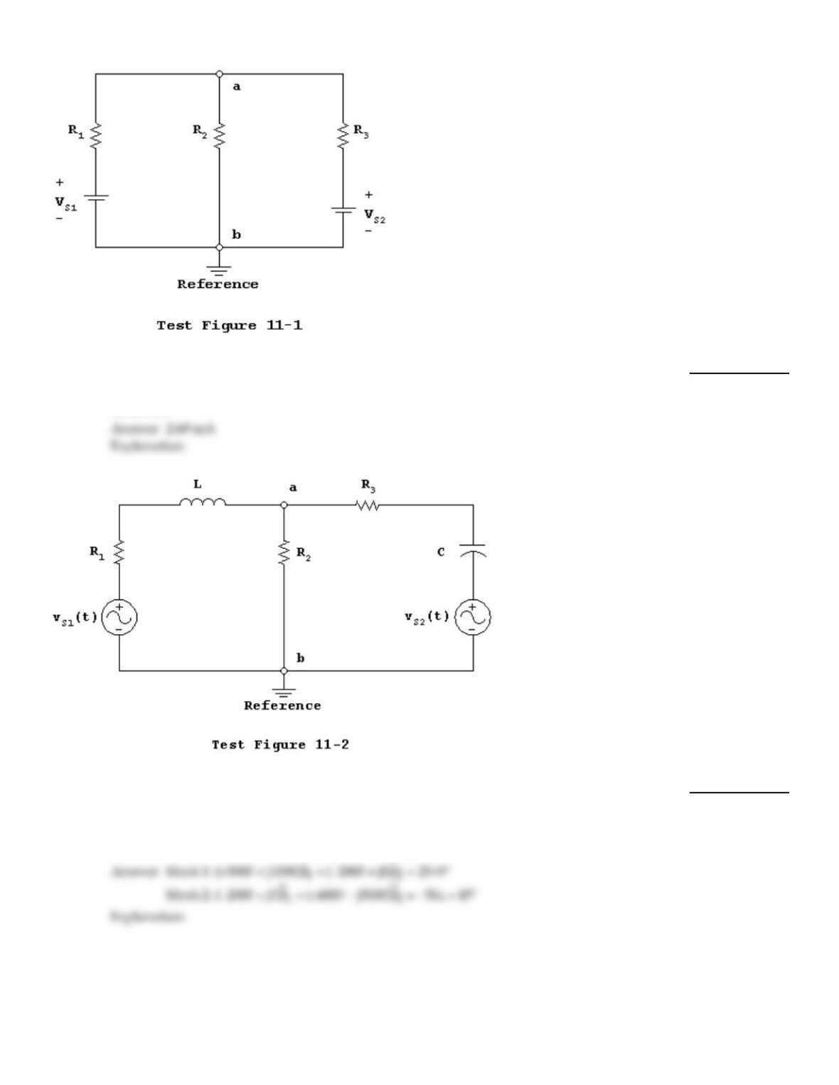
Assume that VS1 = 25 VDC, VS2 = 50 VDC, R1 = 1.0 k, R2 = 10.0 k,and R3 = 5.0 k.
Using nodal analysis, the branch current through resistor R2in Test Figure 11–1is
________.
25)
26)
Assume that vS1(t) = 35.355sin(1000t), vS2(t) = 70.711sin(1000t + 45°),R1 = 1.0 k, R2 = 2.0
k, R3 = 2.0 k, XL = 1.0 k,and XC = 5.0 k.For Test Figure 11–2, assume that the mesh
currents are defined in the clockwise direction with I1in the left mesh. The equation(s)
needed to solve for the mesh current(s) is (are) ________.
26)
7
27)
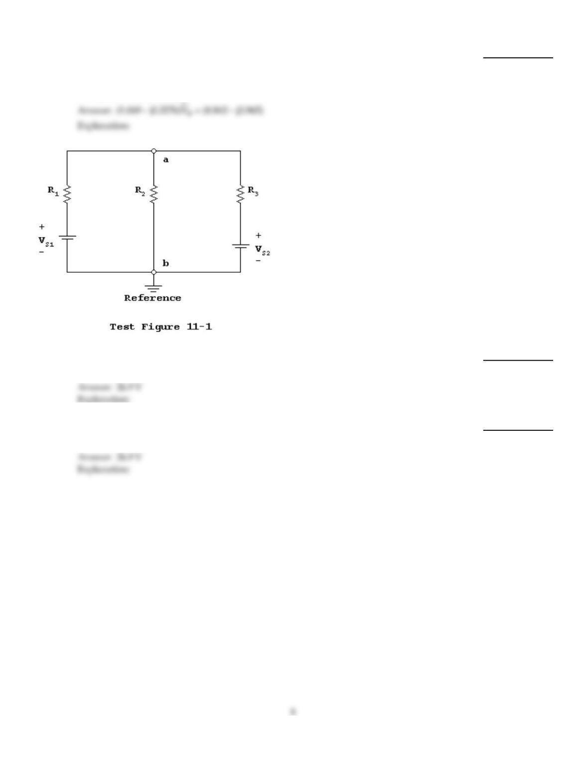
Assume that vS1(t) = 35.355sin(1000t), vS2(t) = 70.711sin(1000t + 45°),R1 = 1.0 k, R2 = 2.0
k, R3 = 2.0 k, XL = 1.0 k,and XC = 5.0 k.Assume that the reference node for the
circuit in Test Figure 11–2is as shown, the equation(s) needed to solve for the RMS node
voltage(s) is (are) ________.
27)
28)
Assume that VS1 = 25 VDC, VS2 = 50 VDC, R1 = 1.0 k, R2 = 10.0 k,and R3 = 5.0 k.
Using mesh analysis, the voltage across resistor R2in Test Figure 11–1is ________.
28)
29)
Assume that VS1 = 25 VDC, VS2 = 50 VDC, R1 = 1.0 k, R2 = 10.0 k,and R3 = 5.0 k.
Using nodal analysis, the voltage across resistor R2in Test Figure 11–1is ________.
29)
30)
Assume that vS1(t) = 35.355sin(1000t), vS2(t) = 70.711sin(1000t + 45°),R1 = 1.0 k, R2 = 2.0
k, R3 = 2.0 k, XL = 1.0 k,and XC = 5.0 k.Using nodal analysis, the RMS voltage
across resistor R2in Test Figure 11–2is ________.
30)
31)
~
~ ~
Awye (Y) configuration of impedance has the following impedance values: 1 = (100 –
j300) ,2 = (100 – j300) ,and 3 = (100 – j300) .The values for each of the impedance
in the delta ()configuration are ________.
31)
32)
Assume that VS1 = 25 VDC, VS2 = 50 VDC, R1 = 1.0 k, R2 = 10.0 k,and R3 = 5.0 k.
Using mesh analysis, the branch current through resistor R2in Test Figure 11–1is
________.
32)
TRUE/FALSE. Write ‘T’ if the statement is true and ‘F’ if the statement is false.
33)
When using nodal analysis, the current direction in each branch is always arbitrary.
33)
34)
The general nodal analysis approach requires that you indicate all branch currents (including
direction).
34)
35)
The general nodal analysis approach requires that you write each branch current (except branches
with current sources) in terms of adjacent non–trivial node voltages.
35)
36)
The only useful purpose for delta–wye conversions is for analyzing bridge circuits.
36)
37)
When there is current flowing through the bridge arm, the bridge is considered to be balanced.
37)
38)
You can determine the branch currents from the mesh currents.
38)
39)
You cannot determine component voltages from the branch currents.
39)
40)
Superposition is always the easiest analysis method, especially when there is alarge number of
sources and/or number of voltages and/or currents to be determined.
40)
41)
Awye configuration of resistances is connected in aconfiguration that looks like atriangle.
41)
42)
Adelta configuration or resistances is connected in aconfiguration that looks like a“Y” or a“T.”
42)
43)
Mesh and nodal analysis techniques have standard procedures that are applicable to all circuits.
43)
44)
The delta–wye conversion equations for AC circuits correspond to the DC delta–wye conversion
equationsexcept that impedances are used instead of resistances.
44)
45)
The general nodal analysis approach requires that you identify and label all non–trivial nodes,
including areference node.
45)
46)
The general nodal analysis approach requires that you write Kirchhoff’s voltage law at each
non–trivial node (except the reference node) in terms of the branch currents.
46)
47)
When doing mesh analysis, once you express the voltage across each passive component as the
branch current times the resistance (DC) or impedance (AC), express each branch current in terms of
the appropriate mesh current(s), and insert the “branch currents in terms of mesh currents” into the
KVL equations, you must solve the simultaneous KVL equations for the mesh currents.
47)
48)
When using mesh analysis it is best to assign voltage polarities across each passive component that
corresponds to each mesh current direction.
48)
49)
Zero current flows through the bridge arm when the bridge is balanced.
49)
50)
The standard procedures of mesh and nodal analysis make these techniques usable for circuit
simulation software.
50)
51)
The only time that abridge is balanced is when all resistances are equal.
51)
52)
When using mesh analysis it is best to assign abranch current in each branch, generally with the
mesh current directions in mind.
52)
53)
Abridge circuit hasaresistance (or impedance) across two points in the circuit that makes
straightforward series–parallel circuit analysis unusable.
53)
54)
It is possible to determine other voltages and the branch currents from the node voltages
determined using nodal analysis.
54)
55)
Mesh analysis requires that you apply Kirchhoff’s current law around each mesh.
55)
56)
The general mesh analysis approach requires that you assign amesh current (including direction)
to each mesh.
56)
57)
When using nodal analysis, the reference node is usually the ground of the circuit or the node with
the greatest number of connections.
57)
58)
The general nodal analysis approach requires that you substitute the branch current expressions
into the KCL equationsand solve the simultaneous equations for the node voltages.
58)
Answer Key
Testname: C11
Answer Key
Testname: C11
14